This week we had to make something big with a CNC machine. In our fablab, we have a Shopbot with a 2,4m * 1,2m workspace.
I decided to make a desk, that I would use to continue with my projects in my house.
The particularity of my desk is that it has no visible union. Even if everybody told me to use Press Fit, I really wanted to do something different,
something more aesthetic because when we think about fablab fourniture, it is most the time made with Press Fit. In general the result of my work, was good,
however I discovered that it was not a good idea to make the Fingers of my union in this compress word,
I later found on internet that people make holes on the desk and on the legs and to unify them, they use wood plugs because they are much stronger,
because they are not made of compress wood.
Other Solution For Joints

To make the design of my desk, I used Fusion 360 with Parametric Design. The parametric design helps me a lot because during the design process,
I used to ask to other people what they think about it, and most the time I adjust the dimension, and with parametric design if you adjust one thing,
the others also adapt them to make the changes fit. Here I show you the joints part because it is the most complex one, the other parts are very simple.
Desk Design Fusion 360
Legs Design Fusion 360

This is the 3D design of my joints, as you can see there is 4 fingers by joints and in reality they are only here to give to the leg some more strength but what will give the real strength is the leg that will be 9mm inside the board.
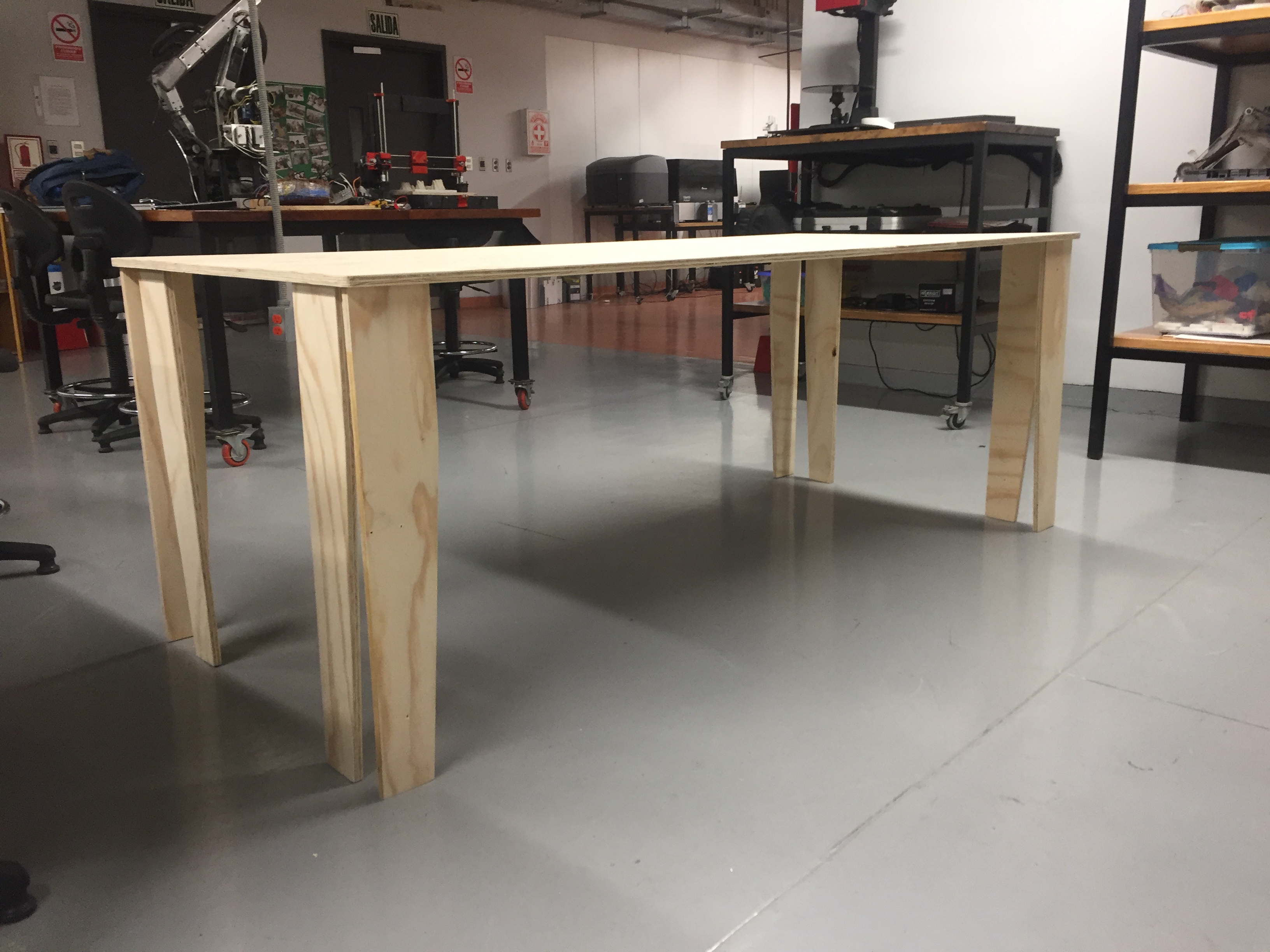
To give even more strength to the desk, I put 8 legs. However with the final result, what I was able to see is that the desk has not a lot of diagonal strength and that for some reason,
the legs have not the exact same dimension so they don't all touch the ground. I think that it could be use full to add adjustable legs to the desk.
Adjustable Legs

For the leg design, I decided not to do them only like a rectangle because I wanted to be sure that if somebody sit in one side of the table, it has enough space for the legs. Also, as you can image, it would be impossible for me to cut with the CNC machine the negative part of the fingers (holes), so I just cut the legs with the CNC machine and later, with an 8mm end-mill and a drill, I made the holes with the help of a wood pattern that I made to test the joins sooner.

I decided to mill a positive and a negative part, of the join before milling the whole thing because I wanted to test how strong was the join. The result was very good thank to the ⅛ drill that we used.

As you can see here, both part the positive and the negative fits perfectly well and when I tried to separate both after, I had to use a screwdriver and it even broke the positive part. It has been a good way to know that with this system, it would be impossible to separate the legs after the installation.

The first thing to do in Vcarve is to configure the material, for that you have to put the dimension of the entire piece of wood that you are going to use and the thickness of the material.
In my case I had a 15.7mm wood, but the Shopbot had a sacrifice bed, that we are going to use because the humidity makes the material none homogeneous and in some parts it is less that that and in others it is more,
so when you cut, we advise to cut 16mm to be sure that it will be easy to detach all the pieces. Once you have your material properties in the system,
you can see the space that you have available to put all the pieces and make sure to make everything fit well.
Vcarve File

Once I had my workspace, I had to place each element in a way that could give enough space between each element and that would make everything fit in the area.

Before that I didn't knew how important the tap was. During the process, in one leg, where we didn't put enough taps, because of the force made by the drill rotating very fast, we damaged just a bit the wood, and I had to rectify it later with some glue and polishing it. Basically the taps are small bits of wood that you leave between the object that you are cutting and the area of work.

My instructor, advised me to use a ⅛ mill for the milling of the joints because it was a precise one. In Vcarve you have to configure them. In this case, it was already configured but I had to modify some parameters in orders to fit the chipload for this material. As you will see later, I used a very useful online calculator, where it gives you the data for many materials and between others, mine which was hardwood. In my case with a ⅛ end-mill the chipload had to be between 0.003" and 0.005". To fit this, the rpm had to be 14000 and the feed rate, 120 inch/minute.

Once I selected all the unions in my desk to make the pocket process, I choose 9mm as my depth, the end-mill that i was going to use and calculated the trajectory.

This is the trajectory that the Shopbot was going to do for the unions milling.

As Neil advised us, I decided to do a Roughing process with a ¼ " Down-cut end-mill for the first 2 millimeter of the milling. Thanks to that, we had to polish less. In this case, I also used the chipload calculator, in this case we put the rpm in 16000 and the feed rate to 450 mm/min, which gave us a chipload of 0.006. The optimal would be between 0.009" and 0.011" but my instructor told me, that it was not a problem if it was at 0.006" (and it was not a problem!).

For the finishing process, I used a 6mm end-mill with basically the same parameters than the ¼" one.

As I mentioned before, this is the online calculator that I used to know the parameters that I had to use for each end-mill.
You basically have to put the number of flutes that your end-mill have and you have to play with the value of rpm and feed rate,
to obtain a chipload in the range of the recommended above. In my case, my instructor recommended me to do not use less than 12000 RPM for this kind of material.
ChipLoad Online Calculator

Here you can see the trajectory for the roughing process. In this case, the depth is 2mm and its main is to have clean cuts and to polish less.

Now you can see the finishing process, it is basically the same than the other, but there is an important detail and it is the initial depth, because you could think that it is 0, as I thought but it is 2mm in this case because it is where we the rough process finished. Finally, the final depth is 14mm because it is aditif. It is 14mm more than the initial depth.

The error is telling us that the final depth will be 16mm and that our material has less depth than that. In this case, it is normal because as I said before, it will gives is the security that our pieces will be easy to remove.
")
Here you can see the simulation of the taps that will give the strength to do not have pieces rotanting with the end-mill.
")
In the zeroing process, I thought that as with all CNCs machine I have already seen, we had to do the zeroing with all the axis X,Y and Z. However, the X and Y axis calibrate themself automatically and you only have to calibrate the Z axis. For that, basically we have a piece of metal connected to a digital pin that will be activated by the end-mill touching this plate and thank to that internally the machine already know the thickness of this piece of metal and can know the zero in the z axis. In this case, I am putting a piece of wood under the metal plate to make think the Shopbot that the zero is much higher than it is. With that I was able to air cut and verify that the end-mill doesn't touch the screws.

The milling process has been very long, nearly 3 hours and a half between all the process. We have to remember that it was three different process, and each of them with a different end-mill, so we had to change them and even if it looks easy, we took some time because it is a bit hard. The problem of using this kind of machine is that you have to be aware, and always been checking the pieces in case they need one more screw.

Even if we thought that this kind of thing could never happen, it happened. The computer we were using for the milling process, just decided to restart to install a windows update. So when it finished, we had to ask to the Shopbot program to start from a certain number of line. We tried from one value, but it was to early, so we tried again with another number of line and it was more near from the point where the computer switch off.

Here you can see how is a tap in the real life. Even if in some cases they are very useful, in others they are not enough so you have to add some screw, but in the future I think that I will add some more Taps and I will not need to put some screws.

In this part of the process, I used a polish machine with a sandpaper to clean the pieces of wood made by the end-mill during the cut process. For that I used glasses because it generates a lot of wood powder. I started the installation process, in which I used a rubber hammer to put the legs in the desk.

Finally here you can see that the desk doesn't have visible unions. In general the result was ok, but as I said before, the desk is not strength enough to diagonal forces.
Please Contact Me For Any Collaborative Project