For this week assignment, we had to redesign the echo hello-world board and add at least a button and a LED.
At the beginning, I wanted to add a DC motor with a transistor circuit, but after thinking that I had to add an external power supply,
I decided to make a circuit with a Photoresistor and a LED controlled with a PWM signal.
Because we didn't have SMD Photoresistors, I have to use a through hole one.
")
For the sketch, I based my design on the Fab ISP programmer because most of the components are similar.
Basically I changed the design to make it fit with the design posted Here.
After that, I checked the ATTiny44 pinout to see which of the free pin were Analog Read for the Voltage Divider used to Read the data from the Photoresistor,
and which of them were PWM to be able to control the bright of the LED.
To be more precise about those technologies, we have to understand how works a microcontroller.
Most of them, are able to "read" and "write" digital signals which are the equivalent of 1 or 0 (5v or 0v),
but also to read analog signals (between 0v to 5v) or to write analog signals that in reality are not real analogwrite,
they are PWM signals which is Pulse Width Modulation that are 0 and 1 a certain percentage of time in a certain time lapse.
Thank to that we can control the bright of an LED. All that signals can be in 5v logic, 3,3v logic, 12v logic or 24v logic.
Download Sketch

The routing has been very complicated for me. For me this part must be considered as art because you have to be very creative to make the routing,
I never use the autorouting because it always makes mistakes and at the end, it gives you more work.
I used for the routes a width between 13 and 16 (not sure of the unit) depending the space and of the nature, if it was GND or VCC, it was a bit bigger.
Download Board

After exporting my design as a monochrome picture, I detected a mistake because one of my connection was touching another pin of the microcontroller. To resolver that, I reduced the width of the route in this zone, and also Modified the grid size.

As I said before, I had to change the size of the grid to make 3 routes fit under the microcontroller. But what is exactly the grid. Well, when I wanted to move a bit my route to one side, for one reason it moved a lot to this side and touched the other route and the same happened to the other side. Well this happens because the minimum mouvement is defined by the grid size so the less it is, more precise will be the movement of the routes in the design. To change that, you had to click in view and select grid.

To generate the GCODE, I used Fab Modules with PCB Traces (1/64) for the routes with a 0.15mm cut depth, 4500 rpm, coolant off,
3000 dpi, and in my case I selected tool 3. For the borders, I used PCB Outline (1/32), with a cut depth of 0.6mm, 5000 rpm,
coolant off, 3000 dpi, and in my case I selected tool2.
Download Traces: Traces
Download Outline: Outline

For my first try, I had very bad results, in some parts, the drill touched the copper, in other didn't. After analysing, I found out three coupables, the first one was the double tape which was to thick and the other one was the copper which was buckled and finally the cooper piece was too big reason why the copper was even more buckled.

Here you can see how the copper was. For this reason I decided to use smaller pieces of cooper and I took a special care choosing my copper plate.

Here you can see the evolution of my prototypes, I made many mistakes during the process, but after some hours, the results was quite good.

After 5 attempts, this is my final result without the holes for the photoresistor because the diameter made by the library of the resistor that I used, were too big. The result is very good because the routing is correct and very clear.

Because I didn't made the holes, I decided to use a Dremel to make them. However, even if I had very small drills, I had not the good collets, so my hole is a bit bigger than I wanted.
")
I am sorry, I completely forget to take pictures soldering, but the components that I used in this case were:
For the Microcontroller:
ATTiny 44
Resonator 20mhz
FTDI six pin
ISP 6 pin
1uF capacitor
10k ohm resistor
For the LED:
500 ohm resistor
Led
For the voltage divider of the Photoresistor:
10k ohm resistor
Photoresistor
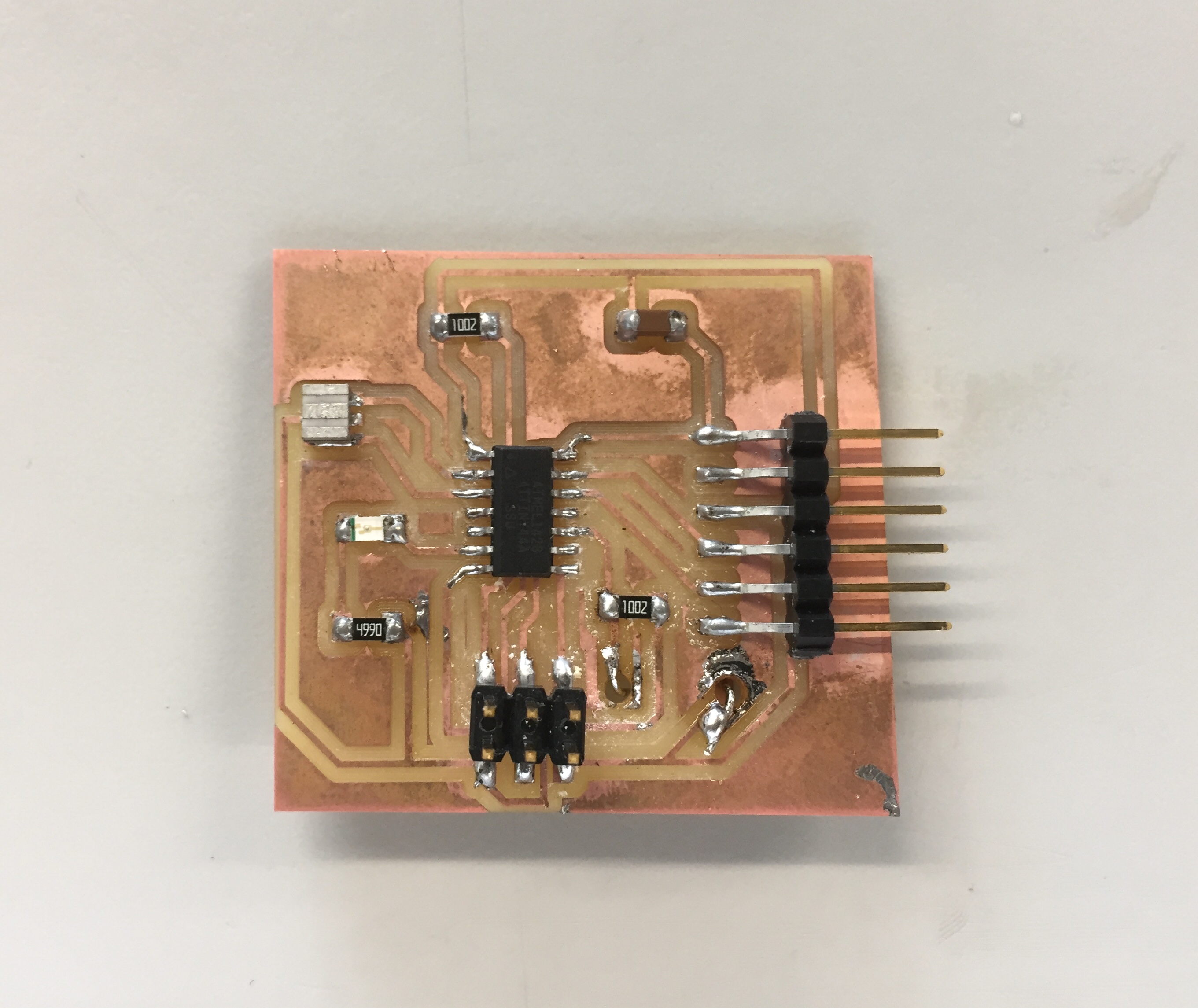
Here you can see the result of the board, and that the green LED of the programmer that tells us that the soldering looks correct.
")
I decided to put my Photoresistor at the back of the board because I had to isolate it from the light to test it, as you can see in the video at the end.

Because I am a big fan of programming with the Arduino IDE, I wanted to learn how to upload sketches from the arduino IDE to my ATTiny44,
so investigating a bit more, I found out, that it is possible to upload them, using nearly anything, the Fab Programer, an Arduino UNO (or others),
and even an avr isp mk2.
But First, it is important to add ATTiny44 to the Boards of Arduino, for that I leave you the link of the JSON that you have to put in the arduino
(you can find many tutorials on internet on how to install new boards in arduino Link):
https://raw.githubusercontent.com/damellis/attiny/ide-1.6.x-boards-manager/package_damellis_attiny_index.json
After that, you have to choose your programmer and finally the clock which is in our case an external 20 mhz because we add a resonator.

Here you can see that I am connecting my Board with FTDI in this case only to supply it. And that I am connecting the arduino to the ATTiny44 like this:
Connect the ATtiny44 Pin 1 to 5 volts (VCC)
Connect the ATtiny44 Pin 14 to ground.
RESET: Connect the ATtiny44 Pin 4 (Reset) to Arduino Pin 10.
MOSI: Connect the ATtiny44 Pin 7 to Arduino Pin 11.
MISO: Connect the ATtiny44 Pin 8 to Arduino Pin 12.
CLOCK: Connect the ATTiny44 Pin 9 to Arduino Pin 13
And Finally you also need to put a 10 μF Capacitor to the Ground and Reset Pins on the Arduino.

Before Programming an ATTiny44 in the Arduino IDE, you have to know the equivalent of the PIN where you connected you things, in the Arduino IDE, for that you can use this image. As you can see, the Arduino Pins are put in brown.

As you can see, the code in this case was very small, basically I am reading the voltaje difference caused by the fluctuation of the resistance of Photoresistor,
and with the help of a map function with basically make a rule of three,
transform this valu that goes from 0 to 255 to a value of 255 to 0 because I wanted less light when I covered the resistor and more when it was free. For the bright of the LED,
I used AnalogWrite that I explained a bit earlier, that creates a PWM signal.
Download Code: .INO File

Because I decided to used brushless motors for my electric longboard, I have to make an electric speed driver which can be controlled with a PWM signal. For that, I decided to use an Atmega328p, and 3 Mosfet driver ir2301, with 6 Mosfets IRF540n to be able to control the Three Phases of the Sensorless Brushless motor. The sketch is based on the design suggested by the datasheet of my Mosfet Drivers.

As you can see, I have not finished yet the routing because it is very complex, and as you see for this first prototype I decided to use only through hole components. The board has two sides and contains the microcontroller, the three drivers and 6 mosfets. You can also see that I have used very big connectors for the input and the three output because a lot of current will flow there.
My board with the LED glowing depending of how near I am from the LDR.
Please Contact Me For Any Collaborative Project