For this week assignments I had to print something with a 3D Printer and also Scan something with a 3D Scanner. What I decided to print is a very small version of what is going to be my Electronic Case for the Longboard. Thanks to that, i will be sure of how it is before printing it in real size in a stratasys Objet 3D printer, which will cost much more. Also, because I had to do something that could not be done with a subtractive method, I decided to make a sphere that is inside a square without walls. Finally, for the 3D scanning, I decided to scan a Gear very similar to the one, I am going to use for the traction in my longboard.
")
After making the first FABACADEMY test for 3D printers, we notice that our 3D printer was not very well calibrated or probably not clean enough, it is the reason why we had no make it twice to finally obtain the results that you can see in the picture. We can clearly see that the 3D printer is able to print very well even with a 0,015" detail. However we had some problems with the end of the cone because it just fall of, probably because it didn't cool as fast as it should.

For my Electronic Case, I designed it in fusion 360, learning how to use some interesting tools like extruding with an angle,
and using shell to make a volume with an specific wall thickness.
Download STL: Case

To make this design, I learned how to use the tool Pipe in fusion 360 to convert a line into a pipe, but also how to make a sphere inside a cube. This design is very interesting because it would be nearly impossible to make something like that with a subtractive method.

To make my GCODE, because I wanted to use the SIGMAX, I decided to use BCN3D Cura. I basically put both STLs in the same bed, to make them at the same time and reduce them to 20% of their real size to be do not have the printer working for hours.

With the help of the layer view in Cura, I have been able to the see how the software planed to print the design (Supports). I have used the recommended config from the software and used 15% of infill because I wanted to have a sphere that was not that heavy. Generated the GCODE and send it to the printer.

As you can see in this picture, the first result of my 3D print was very similar to the 3D design we have been able to the in the layer view,
which let me very surprised. With the help of a paint scraper I have been able to remove the 3D models from the printer because they were quick well fixed and finally with some small clamps,
I removed the support from my 3D models.
Removed Supports

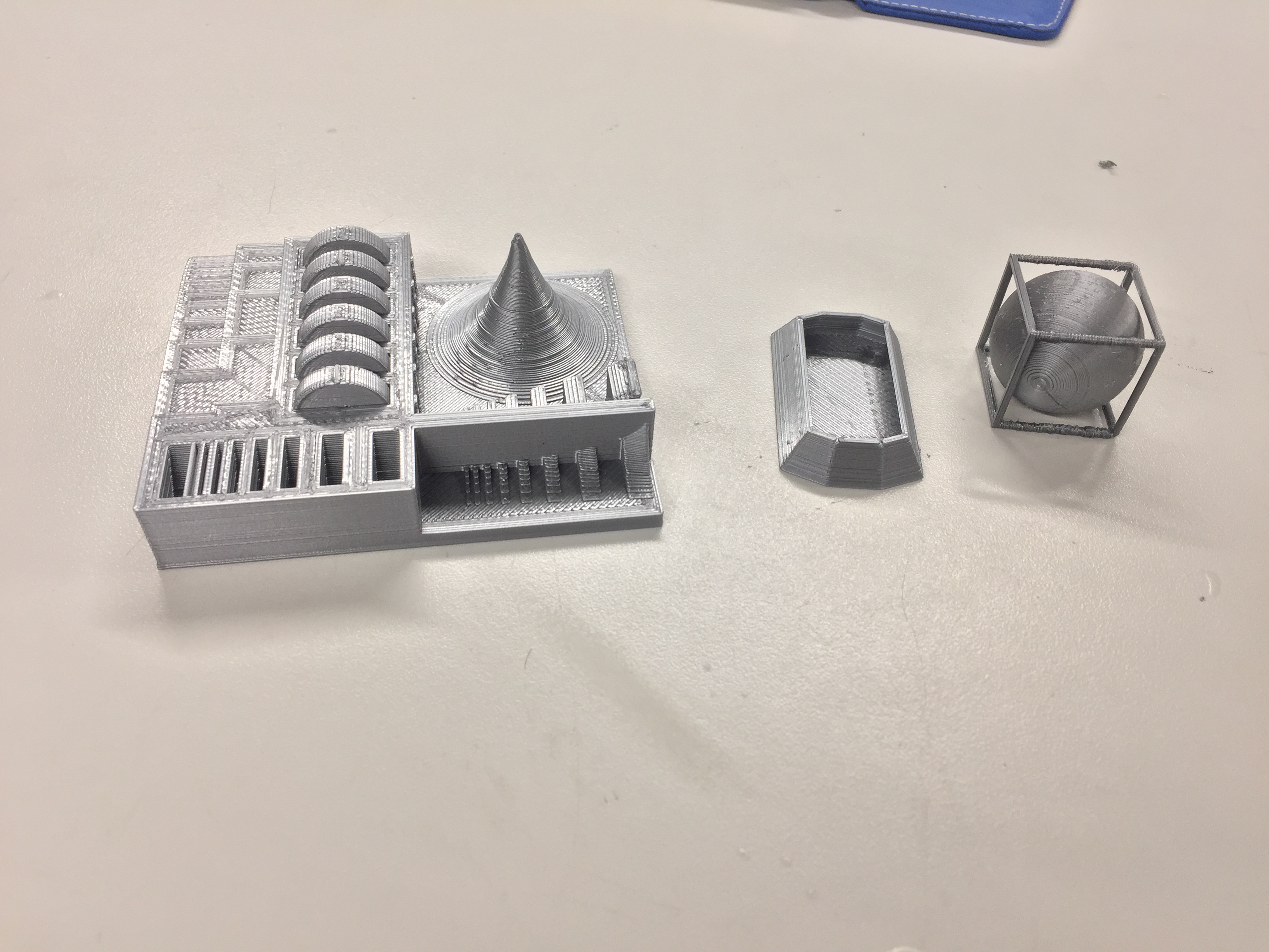
Finally, this is the results of my 3D printed Models.

Because the GEAR I decided to scan was completely black, it would be nearly impossible to scan it. Reason why i decided to put some developer on it, "to make it white". At the beginning I thought that the object had to be completely covered so I applied tons of it. But when my instructor saw that, he explained me that I only had to put a bit of developer to make it a bit whiter.

When I started to 3D scan my gear, I had some problems because the scanner didn't detect the small stickers that it uses as references points, so we had to calibrate it again which was basically put a special surface with a lot of those point of reference and rotate this surface as the computer asked you to. After fifteen minutes, the scanner was calibrated and recognised the stickers very easily.

To scan my Gear which had two important faces, I had to make two different scans. It took me around 40 sets of pictures which I think so, represent 280 pictures unified and assembly thanks to the reference point.

As you can see here, my gear started to appear on the computer after my 40 sets of pictures of each sides. However, because both sides have been separately, we exported it to .stl and import them to Autodesk Meshmixer.

In Autodesk Meshmixer, I imported the two stl files, reverse one of the two objects, join them and start to rotate them to make coincide the holes of the gear. The result was not that good for some reason, and was even worse when I used the reparation tool.

After an hour playing with Meshmixer, this is the best result we obtain. You can see downstairs the 3D model rotating.
This is the STL generated with Autodesk Meshmixer.
Please Contact Me For Any Collaborative Project