For this special assignment, I decided to make a draw machine. In other words, a plotter that is basically two big axis (20cm of work area) and a small one that is to make the pen go up and down. I experienced some big changes during the building process, because I based my design from an existing one, that after modifying some things and cut it, I found out that really it was not as I wanted and many of the materials that I had to install on it, was not compatible so I hadd to redesign most of it. And it has been the same with the electronics because at the beginning I wanted to use the l293d driver because there is a lot of very nice projects on internet that use it to control two stepper motor and 1 servo but really it was not strong enough for the two nema 17.

Electronics:
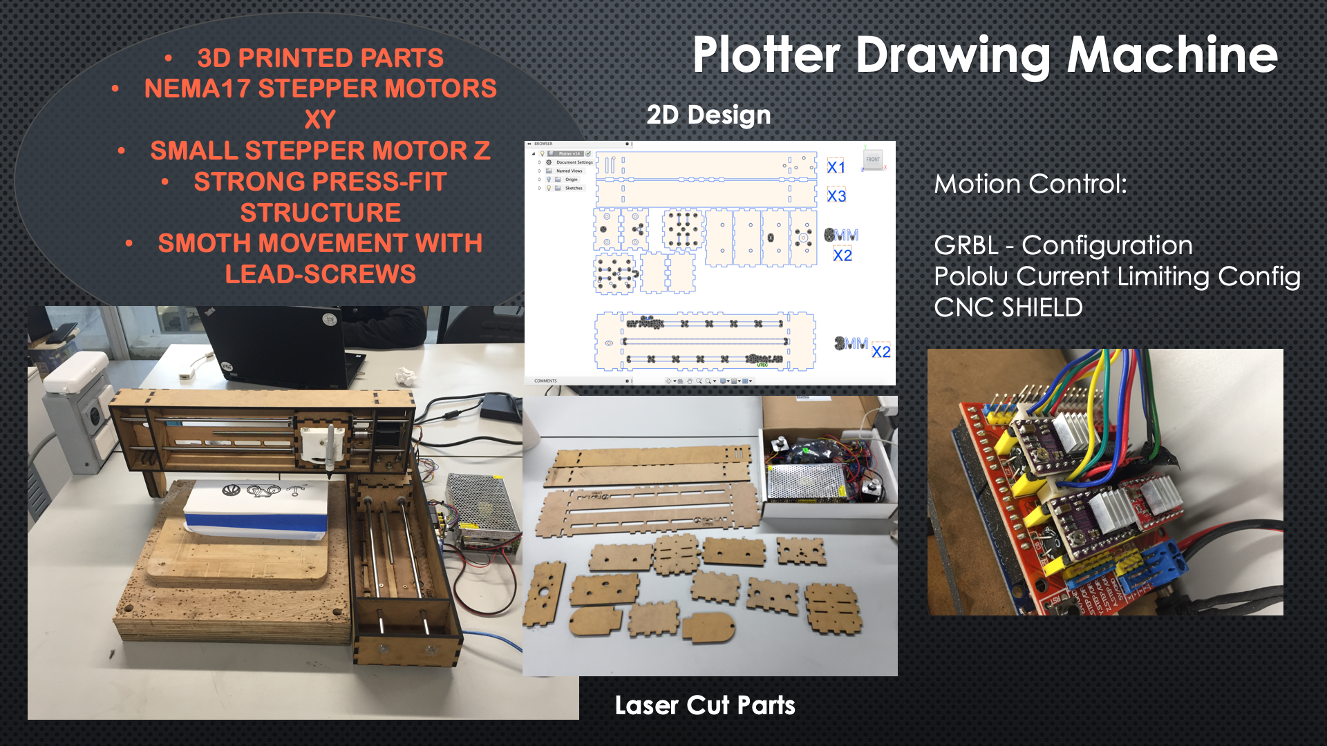
CNC Shield
12V PowerSupply
Arduino UNO
2 Nema 17 42JT47-1684A from JUGETEK
1 StepMotor 28BYJ-48 of 5VDC
Stepper Motor Drivers:
A4988 (Allegro) — Microstepping bipolar stepper motor driver. 8-35V. 1A per phase - Up to 2A per phase (Red)
8825 (Texas Instrument) — Microstepping bipolar stepper motor driver. 8,2-45V. 1,5A per phase - Up to 2,2A per phase (Purple)
Mechanical:
2 T8 lead screws of 300mm
4 8mm Linear Shaft
8 linear bearing LM8UU
2 Flex Coupler 5 to 8
2 Lead screw nuts
1 608 ZZ Bearing
Structure:
Laser Cutted MDF (3 and 6mm)
Software:
GRBL (to control the micro controller)
Universal GCODE Sender (to send orders to the Arduino)
Easel For GCODE Generation

For the 2D Design, I decided to use fusion 360, even if later it caused me some problems because when I export it as a DXF,
there were some lines around the holes with the shape of a polygon that we had to erase manually in the software that the laser cutter place where we went used.
If you don't erase them, you will see that the laser cutter will also was to cut those which is not really a problem because they are inside the circles but if you pay for each minute of the cutting process,
you are wasting a lot of time.You will see three files because one of them is the plotter, the other one is the support leg (cut it twice) for the X axis and the other one is the cylinder to attach the bearing to the two part of the leg.
Download Plotter
Download Plotter Support
Download Cylinder

The 2D design has been a real problem because, I saw that the based design had many errors, as the lack of a support for the X axis, the lack of a real union between the X and Y axis, as well as holes for the cables, but it was not easy to identify small problems as the size of the holes for the linear bearing, or the size holes for the lead screw nuts. But that was not all, some parameters as the size of the pressfit, had to be changed to have a stronger union between each piece. At the end, I was happy because the second design was much more complete and represented better the quality of the design I was looking for. Something very important, is to always know what you are going to use in your machine and adjust your design to make those things fit perfectly. In my case, I used linear bearings instead of simple plastics supports, because bearing gives you a much smoother movement, so a better quality draw but I had to adjust all my design to make them fit for example.

The laser cutting process, has been very interesting this time, because the shapes was not that easy and the amount of material of 6mm that we had was limited, so really, with the person at the laser cutting business, we had to make magic, to make everything fit perfectly. As always, because things are never perfect, I had a problem with one of the things to cut. Only with this small piece, the cutting process was like moved. I found that funny, and decided to take a picture of it. The owner of the laser cutting place, was really surprised because he told me that it was the first time that something like that happens. Some important details are: the laser was a 100 watts one, the power was set to 95% and the speed to 15 mm/s, for the 6mm mdf and for the 3mm mdf, the power was set to 85% and the speed was the same.

After investigating a bit about drawing machines, I thought that it could be a good idea to use a Motor shield made with l293d drivers that came with 2 outputs for stepper motors and that could control a servo that could eventually move a pen up and down (here you can find the link to the GRBL Library for the Servo Integration). However, very soon when I connected the stepper motor, I noticed that they barely move and that the driver was very hot, so I didn't even test with some charge. The problem, was that a nema 17 of the size we had, need too much power for this driver, reason why I decided to use a CNC Shield. The advantage of this board, is that you can connect any pololu driver to the board depending of the amount of current and sound that you want (there is silent drivers).

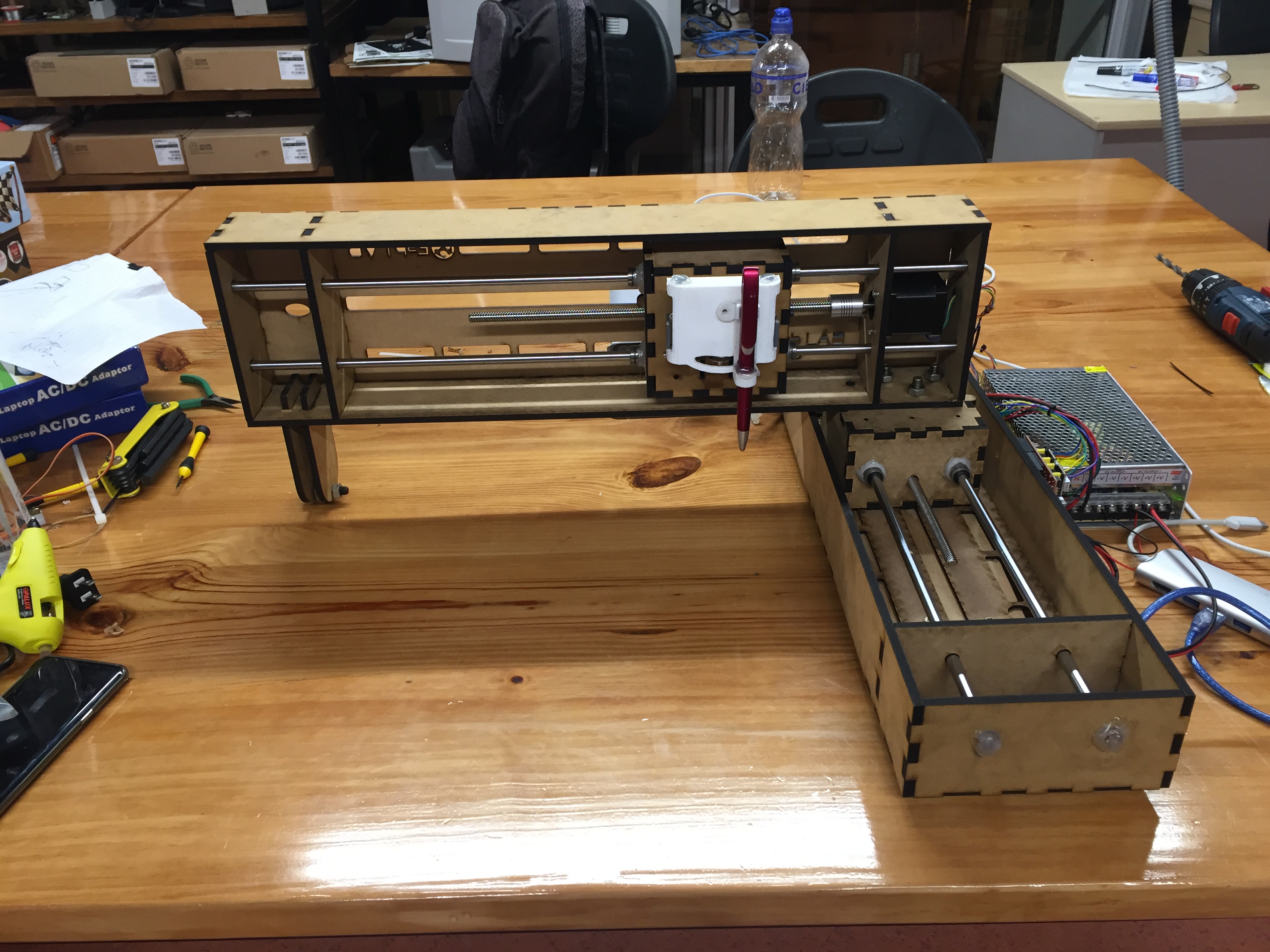
The assembling process, have been very enriching, because I noticed some important details. The first one was that the X axis leg was too tall because the height needed was its, but because of the bearing, it was to tall. To resolve this, I cut a piece of wood and add it at the bottom of the Y axis and with the help of a level, double checked that the height was perfect because otherwise, when drawing, the pen could sometimes draw and sometimes not. The other one, was that, I forget to include some kind of fixation for the linear shaft, so I used some hot glue to fix it. However the rest was very good, the pressfit was strong and everything fit very well.
")
The electronics, was in this case very easy, I used a CNC shield which can be installed in an Arduino UNO, with three Pololu, two 8825 for the X and Y axis and one A4988 for the Z axis. In this case, I wanted to have a very smooth movement and a 1/32 step config was in my case a good choice (but sometimes, the smaller is the step, doesn't mean that the smoother it is, you really have to test and see which config is better). For the smaller Stepper motor for the Z axis, as you know, I used a A4988 which have as the smaller step config 1/16, that I used but really it was not that necessary because the movement doesn't have to be smooth, it goes up and down in two fixed position, there is no in between movement. Here you can download a table with the different jumper configuration for the microstepping for both drivers. After that, I used a power supply that we had in the lab (12V- 20A), which is obviously too much but it was the smaller we had. Finally, here you can also find a video about how to configure the voltage supplied by the drivers, but also here a video talking about the microstepping.

Finally here it is, the result of many hours of work and frustration. The final result is very nice, as you can see there is a 3D printed support for the pen, which is basically the Z axis.
The design of this piece has been inspired on the one made by some UTEC students for a Plotter but with a completely different principle,
their Plotter has a central core and it works with belts, which I think give a better result and a smaller form factor but is less confident and durable.
The Z axis, consist of basically a stepper motor that has a gear that makes tha front piece goes up and down, sliding on two 3D printed axis (there is also a 3D printed part to support the motor).
The results for the moment are good but I have some serious difficulties with the z axis because it makes too much pressure on the paper even if I set correctly the zeroing.
Part1 Z-Axis
Part2 Z-Axis
Part3 Z-Axis
Part4 Z-Axis
Part5 Z-Axis
Part6 Z-Axis

This part, has been probably the worst. Even if my machine worked, I had some serious problems with the Z axis. For some reason, even if I set correctly the zero, It just made a lot of pressure on the pen and my draws was not that precise. After asking some help, and looking in internet we saw that if I wanted to move one of the axes in one mm, it moved like 4 mm. It is only at this moment, that I understood that the problem was the setting mm/step and the reason of this problem was the microstepping. So after watching the videos previously showed and trying many different parameters, I found the perfect ones, and I was now able to make some nice draws. It is important to know, that I used the classic GRBL for this project. Here you have the link to the library, and here you have the link to Universal Gcode Sender that will give you the ability to connect your computer to the arduino, send some gcode, preview the work, move the machine and change the parameters.

After I finished to resolve all the technical problems, I had to generate the GCODE to test it in the plotter. For that, I used EASEL , which is a very intuitive tool. The parameters to have the GCODE, were Outline and as a cut depth, 0,5mm. Finally I had to go to Machine, advanced, and download the gcode. Thank to Easel, you can very easily create Gcodes for plotters and cnc machines for example. Finally, don't forget to choose your material and the size of it (the size is your work area and the material that I chose is Birch Plywood).
Here you can see the Plotter Drawing a bicycle, an anchor and a basketball ball.
Please Contact Me For Any Collaborative Project