computer design
2d to 3d
in this week we learned general ideas about many 2D and 3D software to design our project and make it ready to be Fabricated in the Lab
computer design
first 2D software CorelDraw
I have first tried CorelDraw to sketch some designs like the spinner and learn some tricks to combine and join images.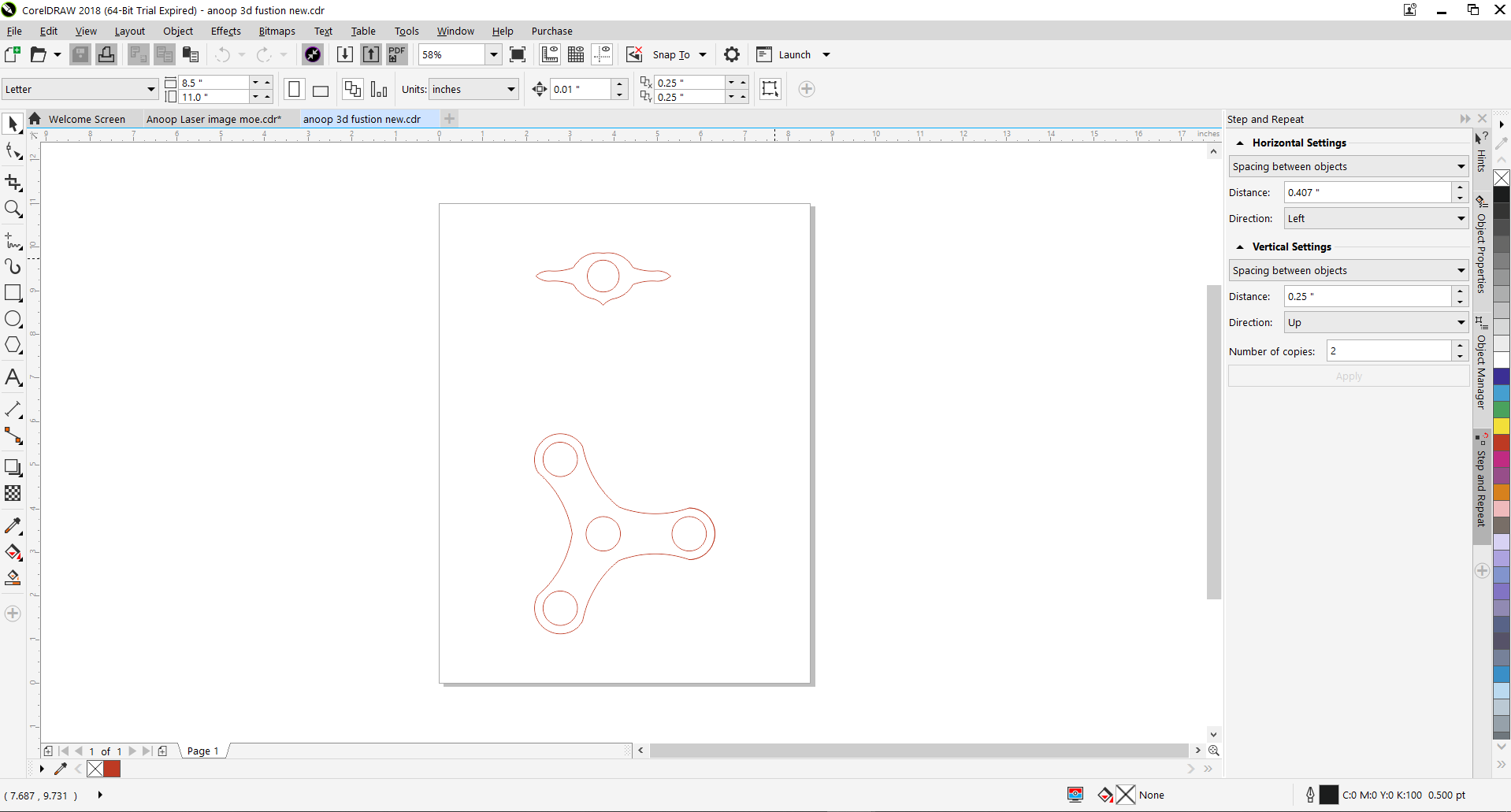
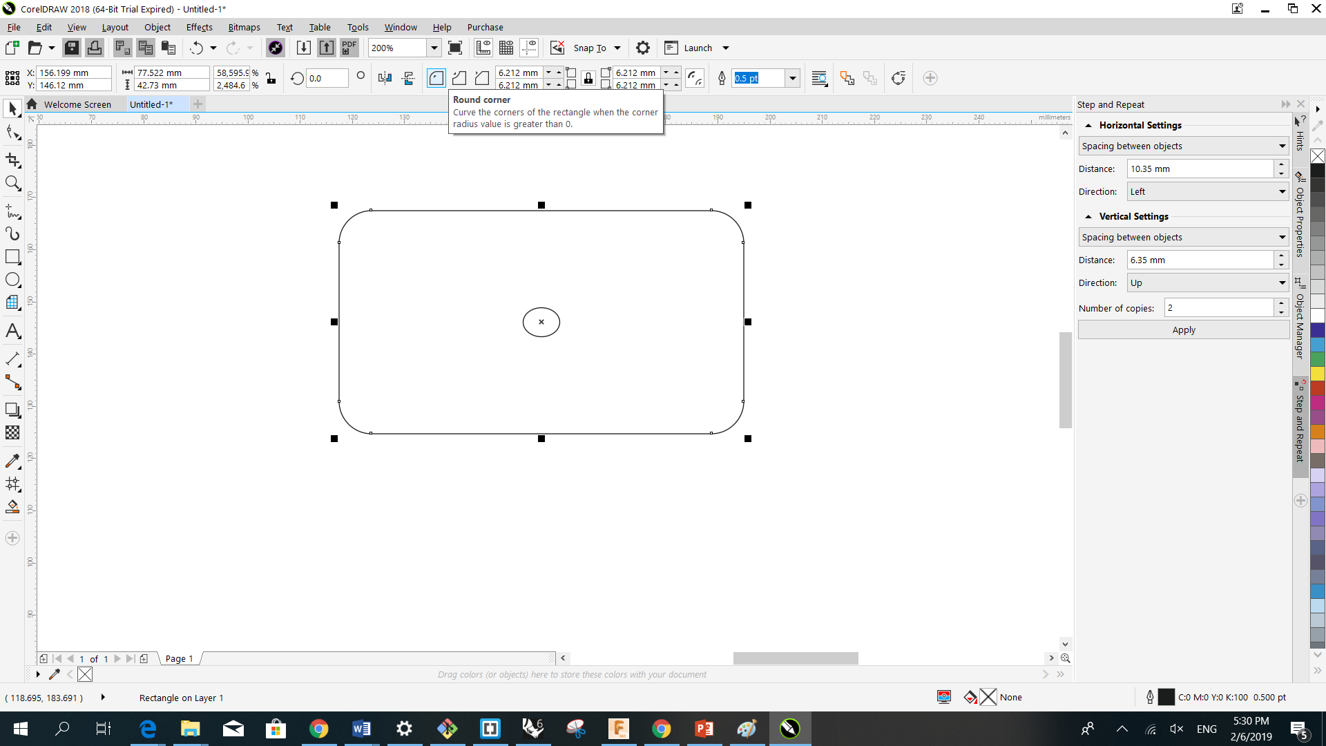
- a picture does not support transparency, so you will always have a rectangular image when saving a Jpeg. However, if you are simply wanting to have rounded corners on your image with white (or the background colour) corners - then grab the Rectangle Mask tool (shortcut key =R) and enter an amount in the Corner Size box in the Property Bar. It is right next to the Feather Edge box. Drag out a rectangular selection the size of your image and you will see the mask has rounded corners. Invert the mask and press Delete on your keyboard
- A Jpeg does not support transparency, so you will always have a rectangular image when saving a Jpeg. However, if you are simply wanting to have rounded corners on your image with white (or the background colour) corners - then grab the Rectangle Mask tool (shortcut key =R) and enter an amount in the Corner Size box in the Property Bar. It is right next to the Feather Edge box. Drag out a rectangular selection the size of your image and you will see the mask has rounded corners. Invert the mask and press Delete on your keyboard
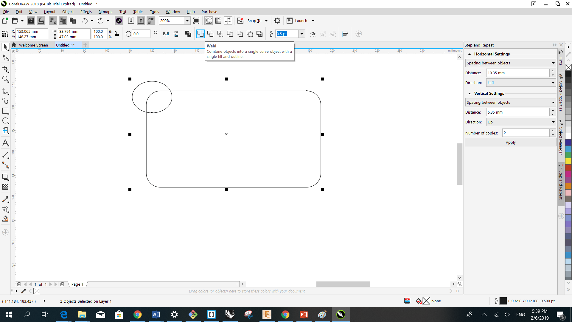
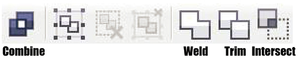
- In Corel Draw there was a "Weld" command. What this did was create a drawing that was the basically the trace of the perimeter lines of a group of objects that intersected (or overlapped) each other thereby creating an outline of the whole object without any internal lines.
many useful tools
used for example trace bitmap to take a vector draw from any picture for easier implementing in CNC machines.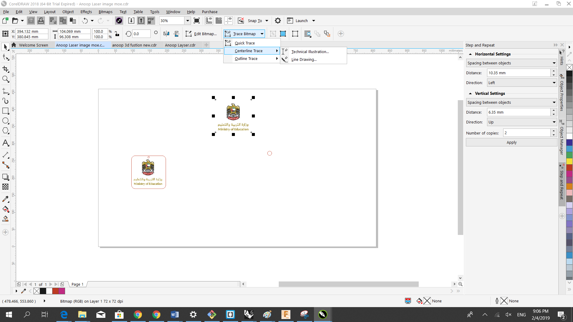
Trying other 3D software
I tried to use also Rhinoceros 6 and I liked the combine tools and used to try some design by grouping a sphere with a cylinder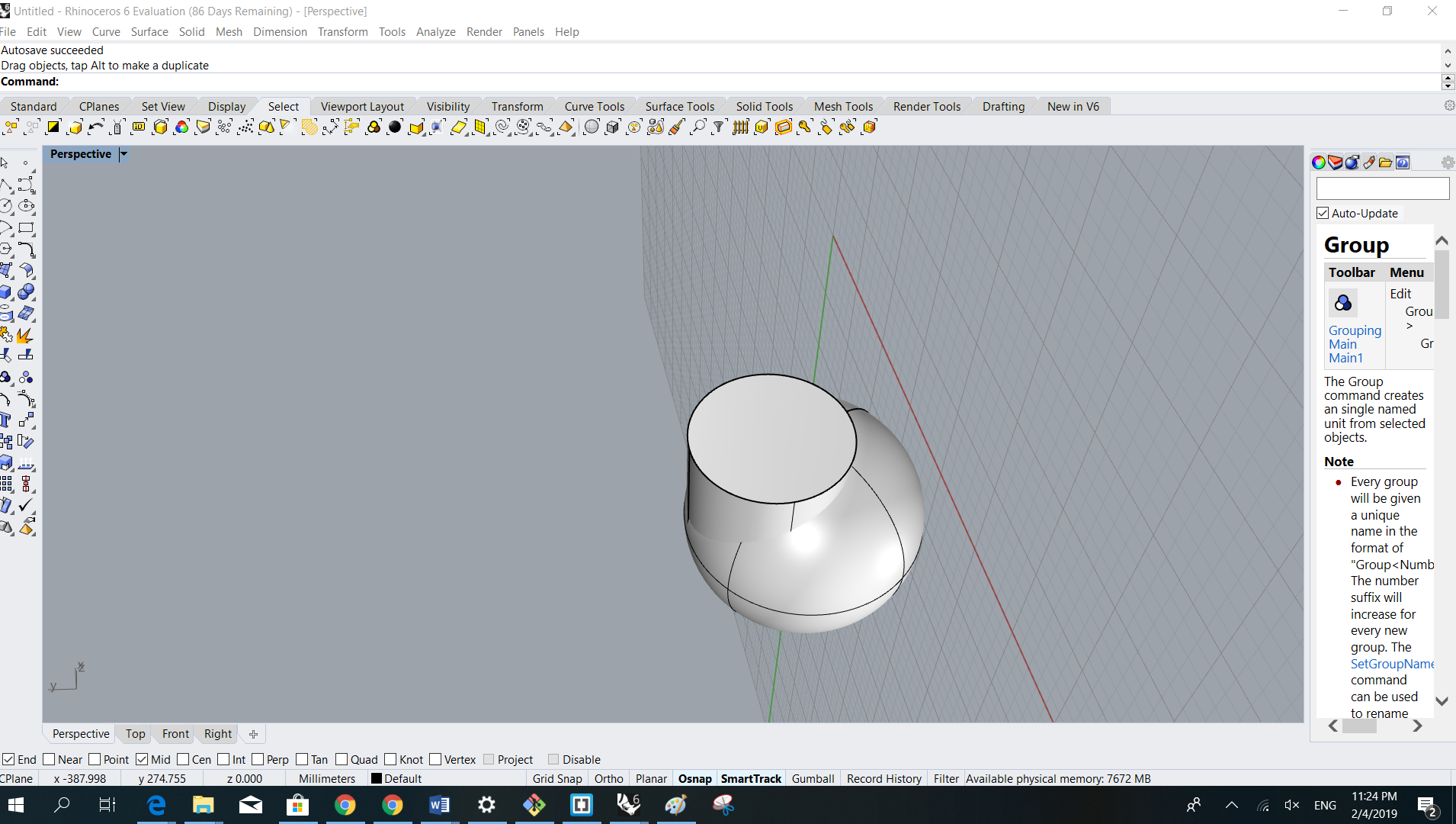
Old is Gold
As to start the faster way to sketch my Robot body I used my Samsung tablet and a pencil and paper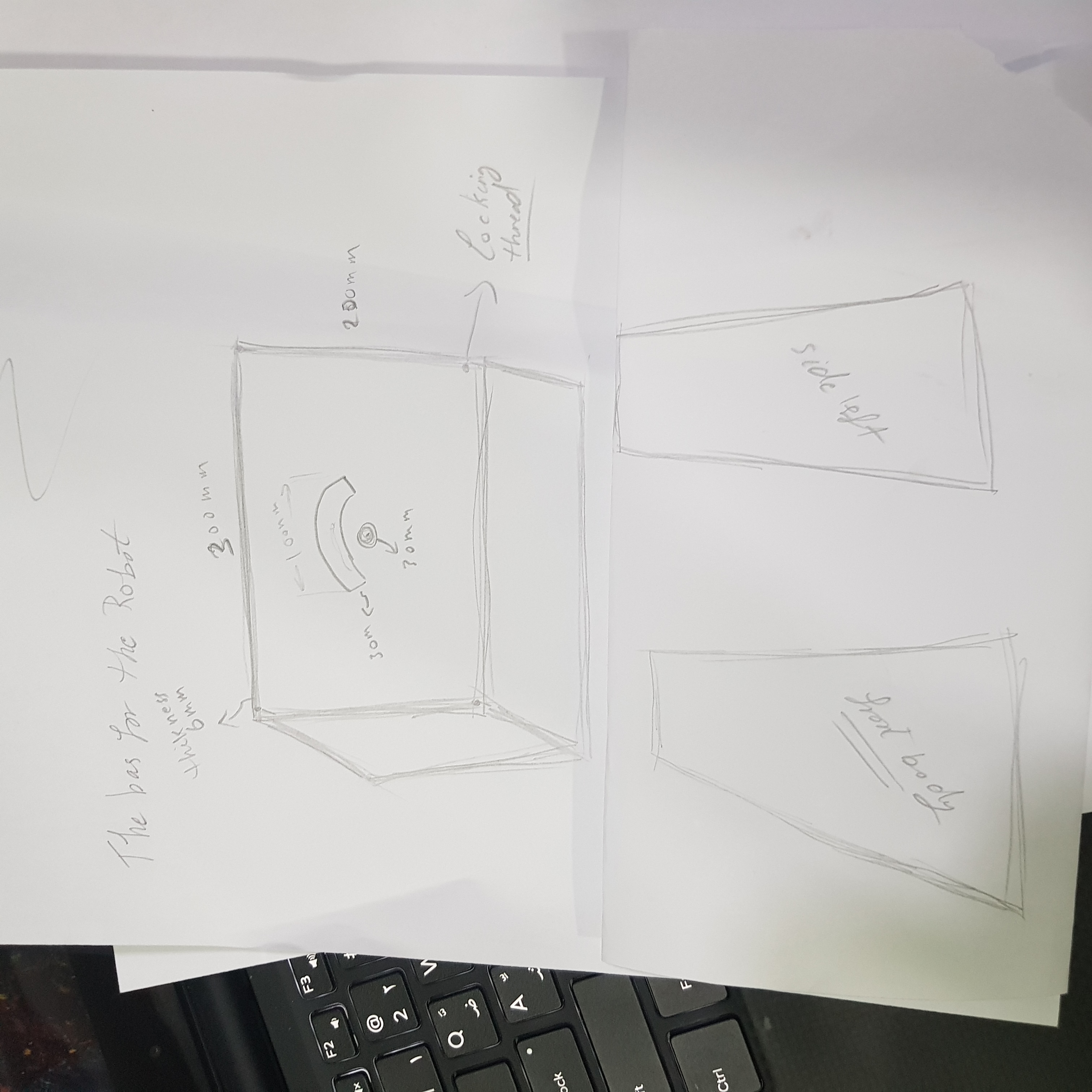
Into 3D design
After trying some 3D software I figured that Fusion 360 is my best choise so I started using it with Mr. Danial help. So I started designing my 3D Robot Body for Base and shaping the base box in fusion was first not an easy task but after learning some tips with Mr. Daniel everything became easier and better.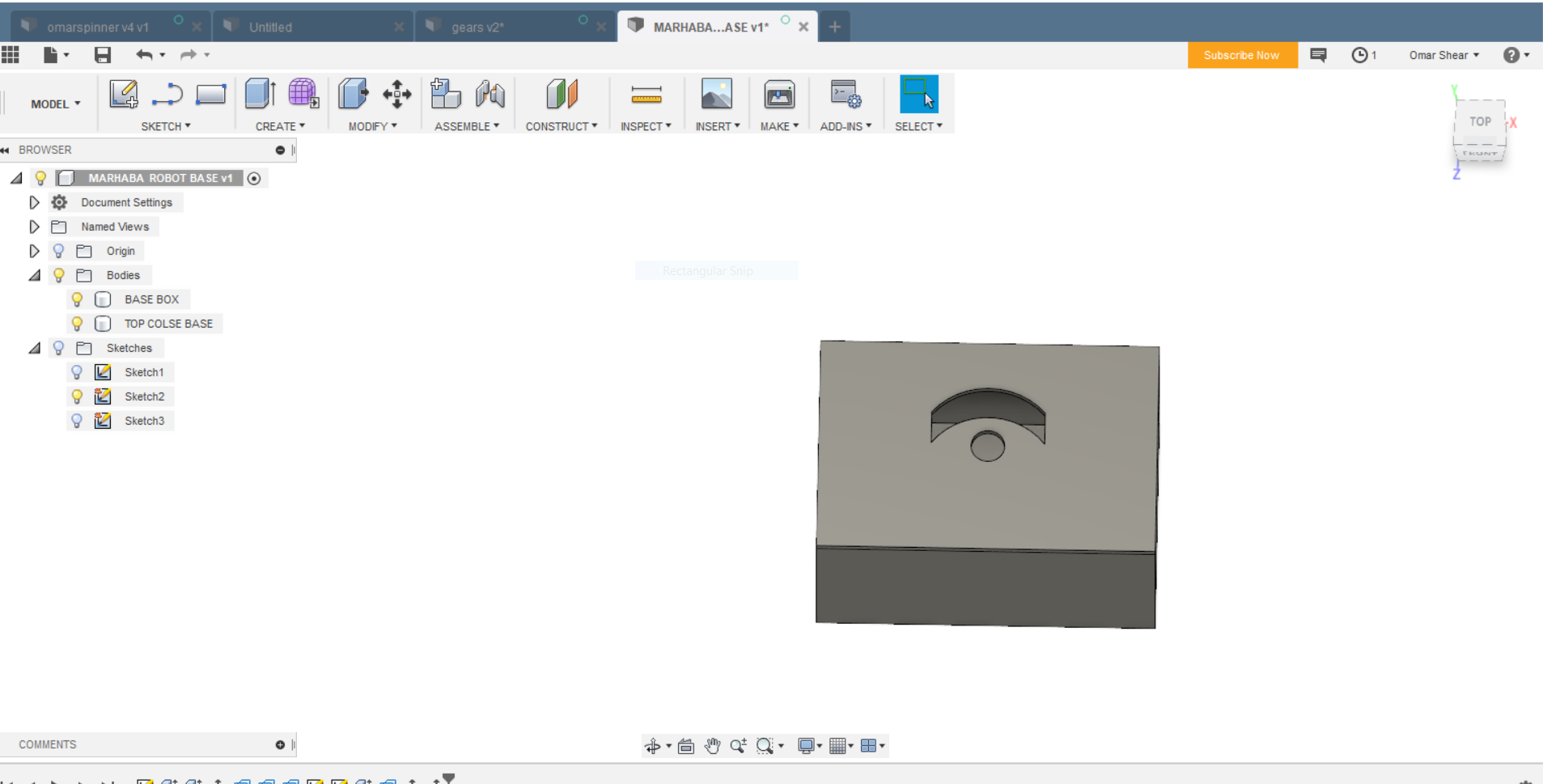
Some tips in useing fusion
The Loft tool can be used with multiple sketches to create a transitional shape between them – think of the relationship between floors on a skyscraper. We can use the Loft tool by selecting multiple profiles or planar faces and optionally guide the shape by selecting rails or a centerline. This tool is ideal for creating different diameters, like that of a soda bottle for example, to connect each sketch together. Be aware of the flexibility of this tool, as there are many options to choose from to influence the body created with the Loft tool.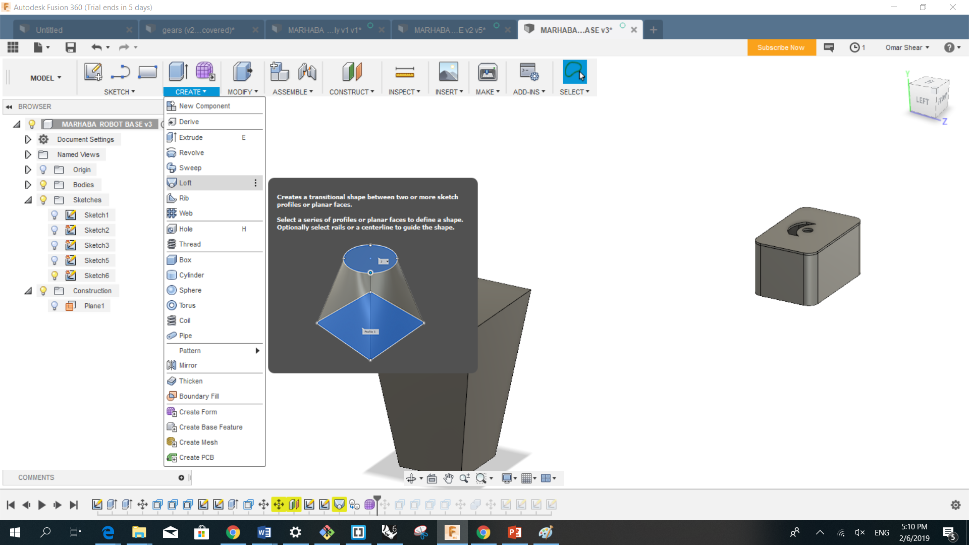
- Sculpt Modify Move
- Model Modify Move
- Patch Modify Move Model, Patch, and Sculpt Move Move Object In direct modeling mode you can pick a face of a solid and use the move command to move it or give it an angle. Now, you can also do this in history mode too! The Move command now lets you move sketch objects, faces, bodies, and components. Bodies... Enables you to move bodies Components Enables the selection of components. Faces Enables the selection of faces both in direct modeling and in the history mode. Sketch Objects Enables the selection of individual sketch objects. This mode moves individual sketch geometry. Selection Select the objects to be moved. Move Type Values are now stored parametrically, and you can edit them later. It also applies to selected points. The Move command captures the final position, not all the incremental ones in-between, and that final position is captured in the timeline. Free Move Displays a manipulator. Use the manipulator to move the object or enter values in the fields.
- Note: Free move is the most flexible but is not captured parametrically. There will be no recording in the parameters table of a free move.
Some tips in useing fusion
Moves a face, body, sketch curve, components, or sketch geometry. The whole geometry.Create Copy
You can now also make a copy (clone) of the body or component you are moving. Make sure you have the Create Copy checkbox selected before you start moving your model. Two features are now at the timeline representing the original object and the copy.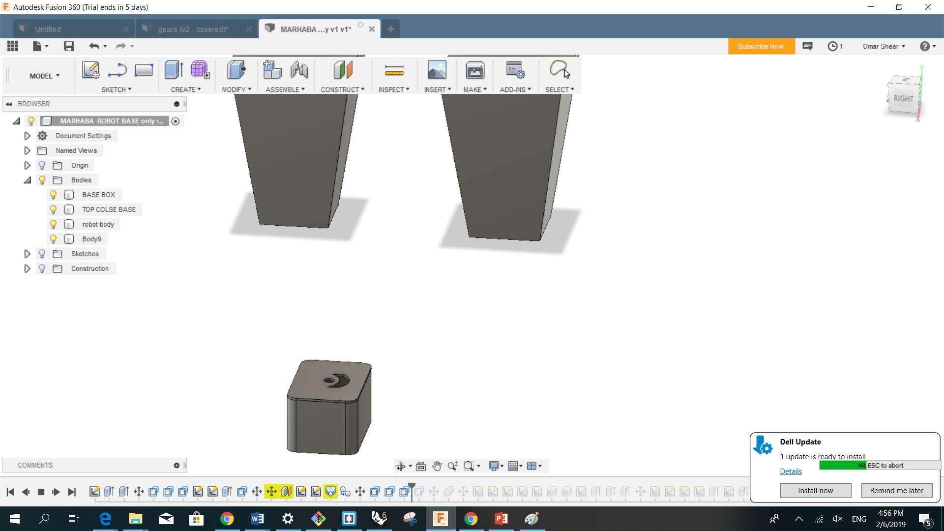
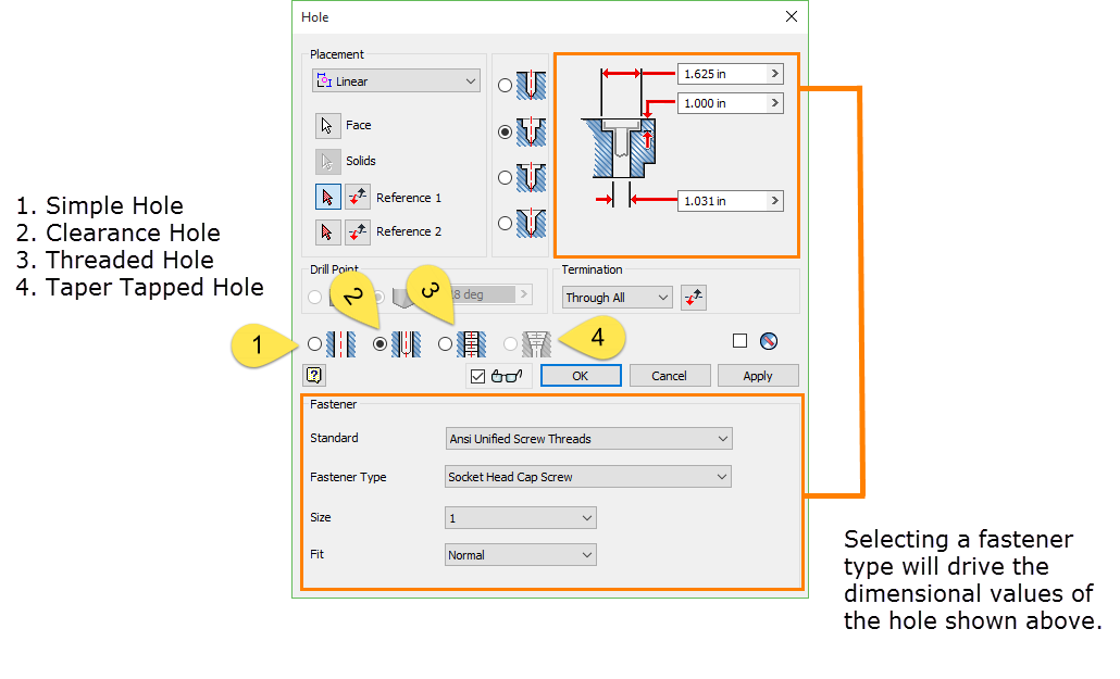
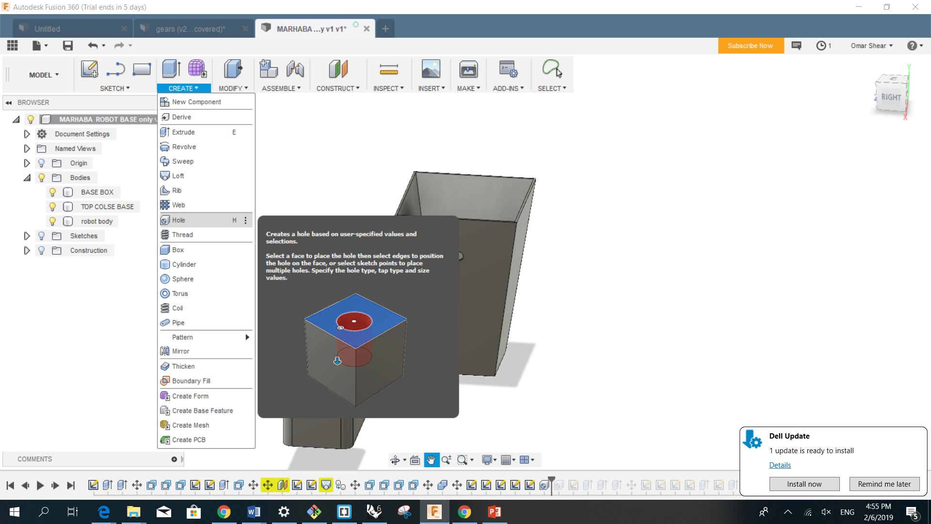
- The hole command in Fusion 360 is an area the demonstrates this update cycle. In a previous build, some of the functionality to locate a hole using Fusion 360 didn't work the way I was hoping it would. However, after an update, things work as I thought it they were intended to. There are features of the hole command still missing, but fingers crossed that a future update will add those missing options.
- There are a few different ways that you can add holes in Fusion 360. You can sketch the holes by drawing a circle and extruding the profile to create a hole, you can place holes directly on the model by using the hole command, or you can also do a hybrid approach by creating a sketch and adding multiple sketch points to that sketch. After the points are added to the sketch, you can use the hole command to place a hole at each of those sketch points.
- I'm not a fan of the sketch a circle and extrude method and here's why. If you need to add any other features to the hole, such as a counterbore or countersink, you have to add them as secondary features. By using the hole command, you can add those features during the hole creation process. For a single hole, I will place the hole directly on the model and reference edges to located the hole. If I have multiple holes of the same size that aren't part of a pattern, I will use multiple sketch points.
Some tips in useing fusion
- the first desgin Robot Body Base
- Most of the main parts ready
My First Robot in 3D Desgin
- All parts togther now