Week 3 - Computer-Aided Design (CAD): How to Make 3D and 2D Models.
Posted on February 6, 2019

For this week's assignment I made my final project's design model in both 3D and 2D.
The programs I used:
Fusion360 (3D Design)
Corel Draw (2D Design)
Using Fusion 360 I was able to convert my sketch that I made by hand to a 3D Model.
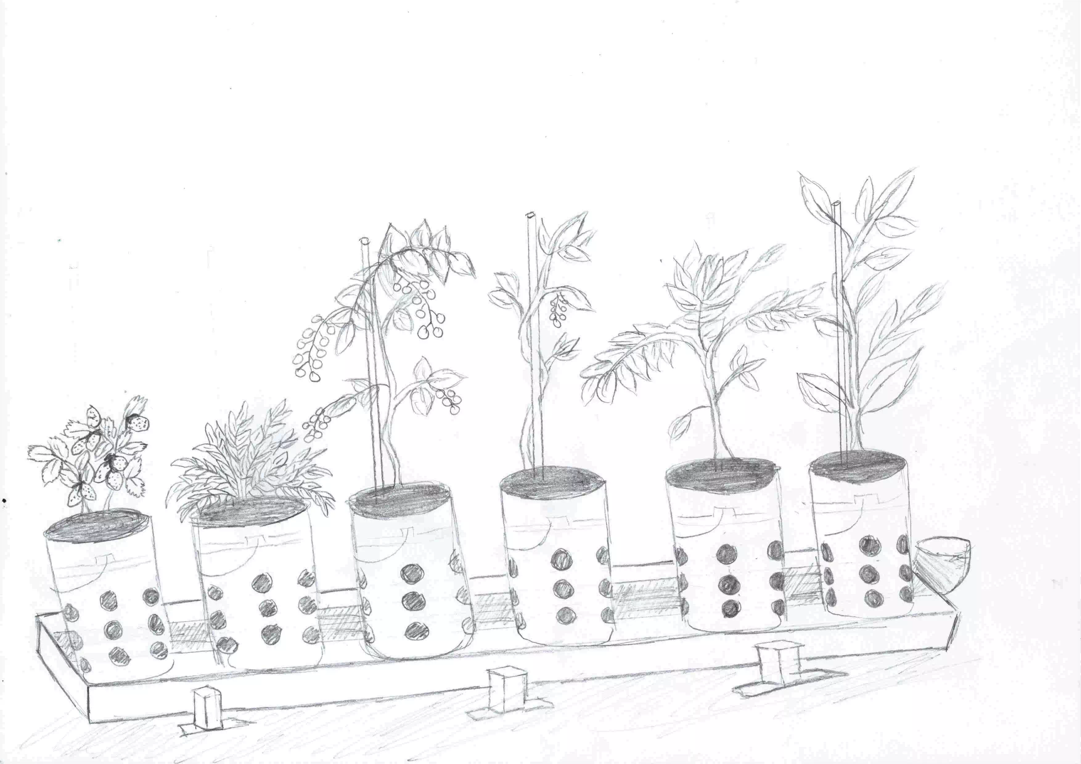
This is my 3D Model of my final project that I created using Fusion 360 .
Alternatively you may download my file here.
The 3D model can be broken down into four parts:
Making the Pots
Creating the Brackets
The Base
The Movements (Putting all the parts together)
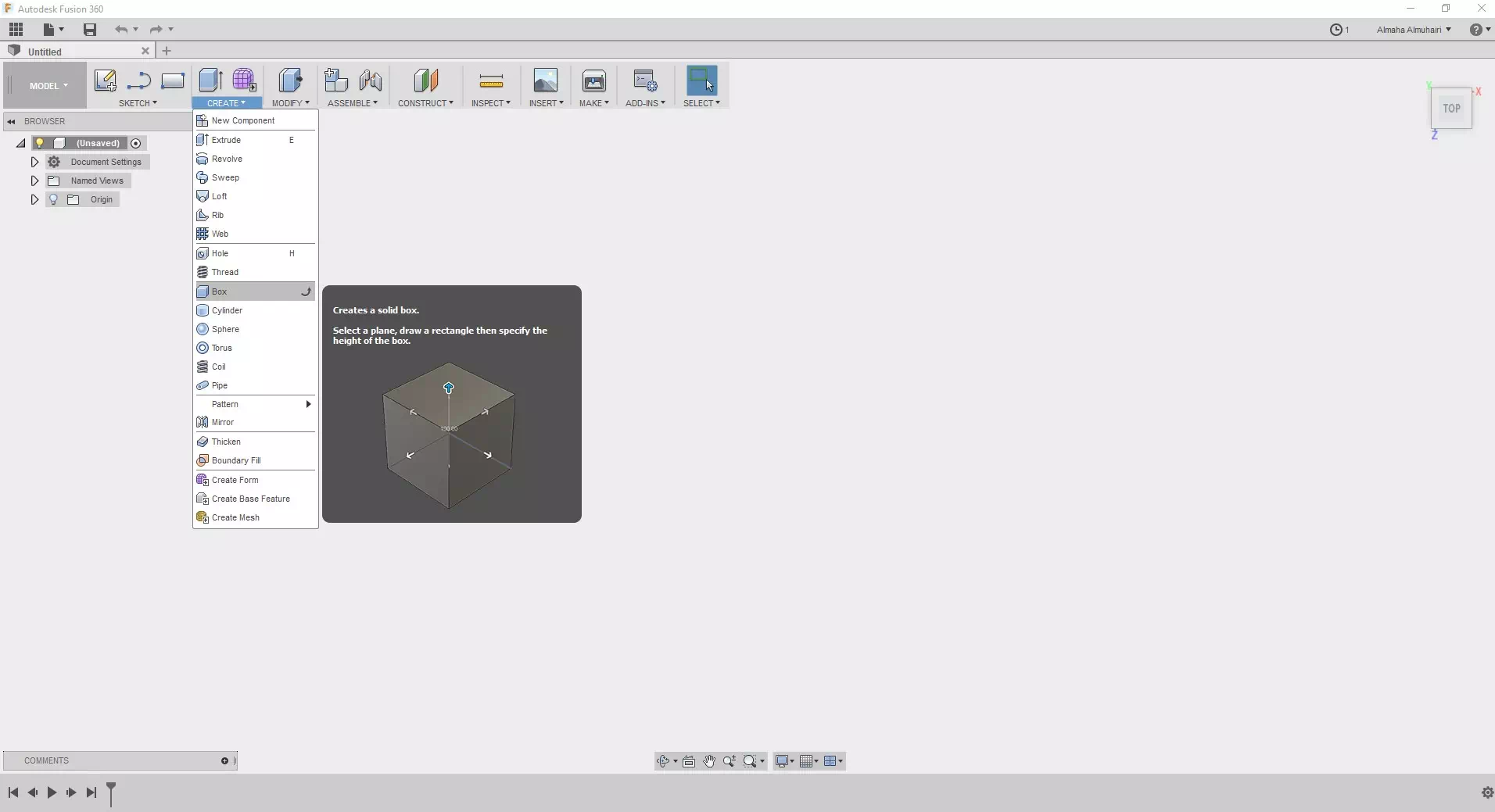
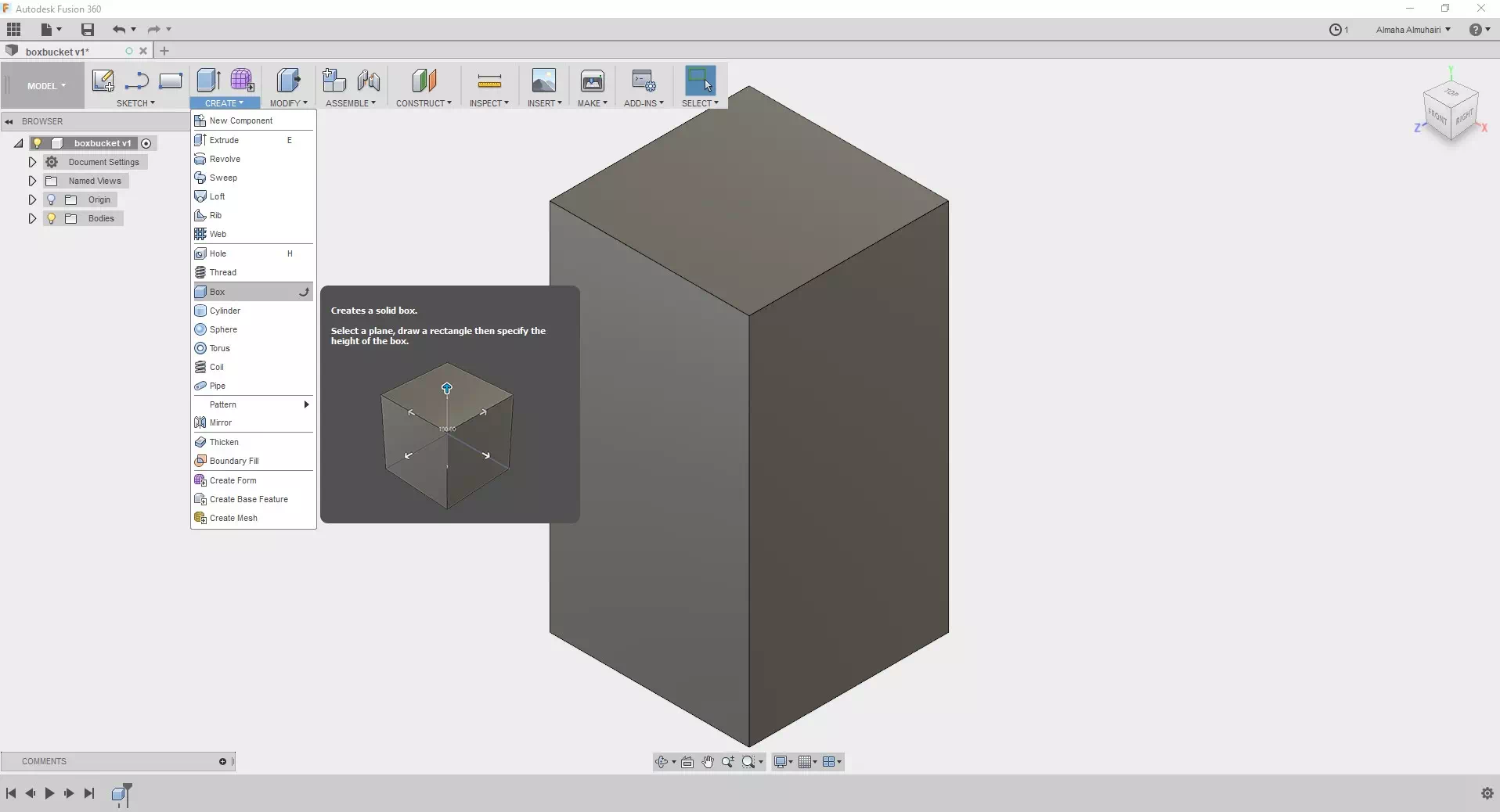
Start by creating a box. Use the create tab.
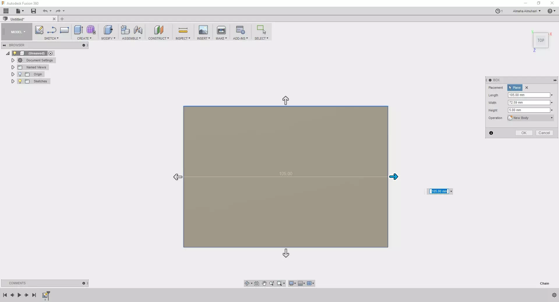
Add your desired dimensions, using the TAB key on your keyboard can help you switch between each dimension (Height, Width, and Length) side.
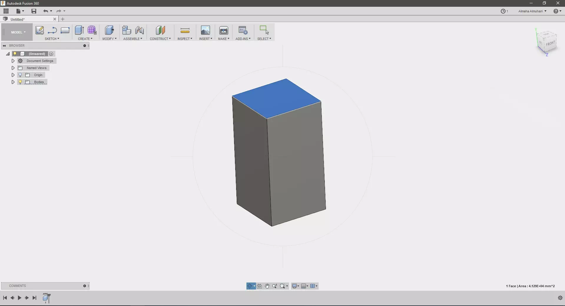
It should extrude to your imputed dimensions.
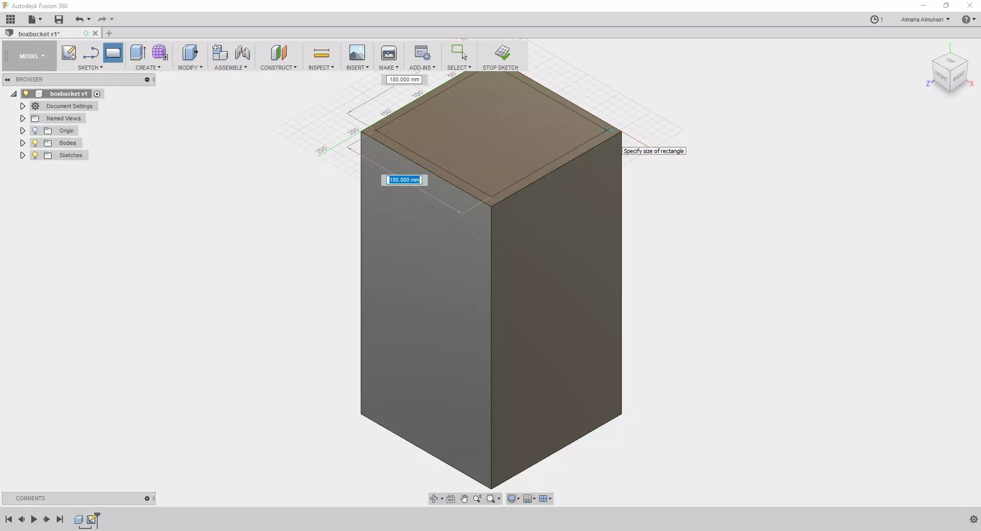
Lets create a two point rectangle sketch this time, place this sketch on top of the extruded box.
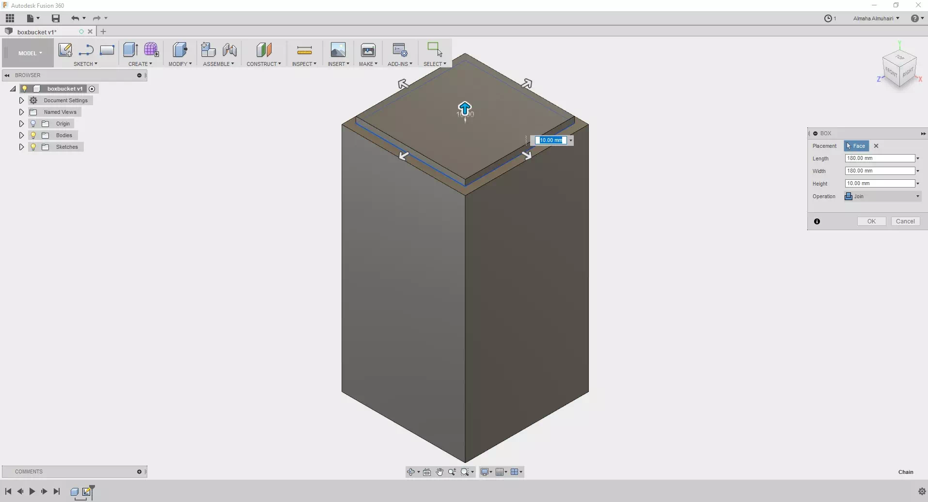
Press the E Key on your keyboard to extrude the new rectangle sketch as a new body.
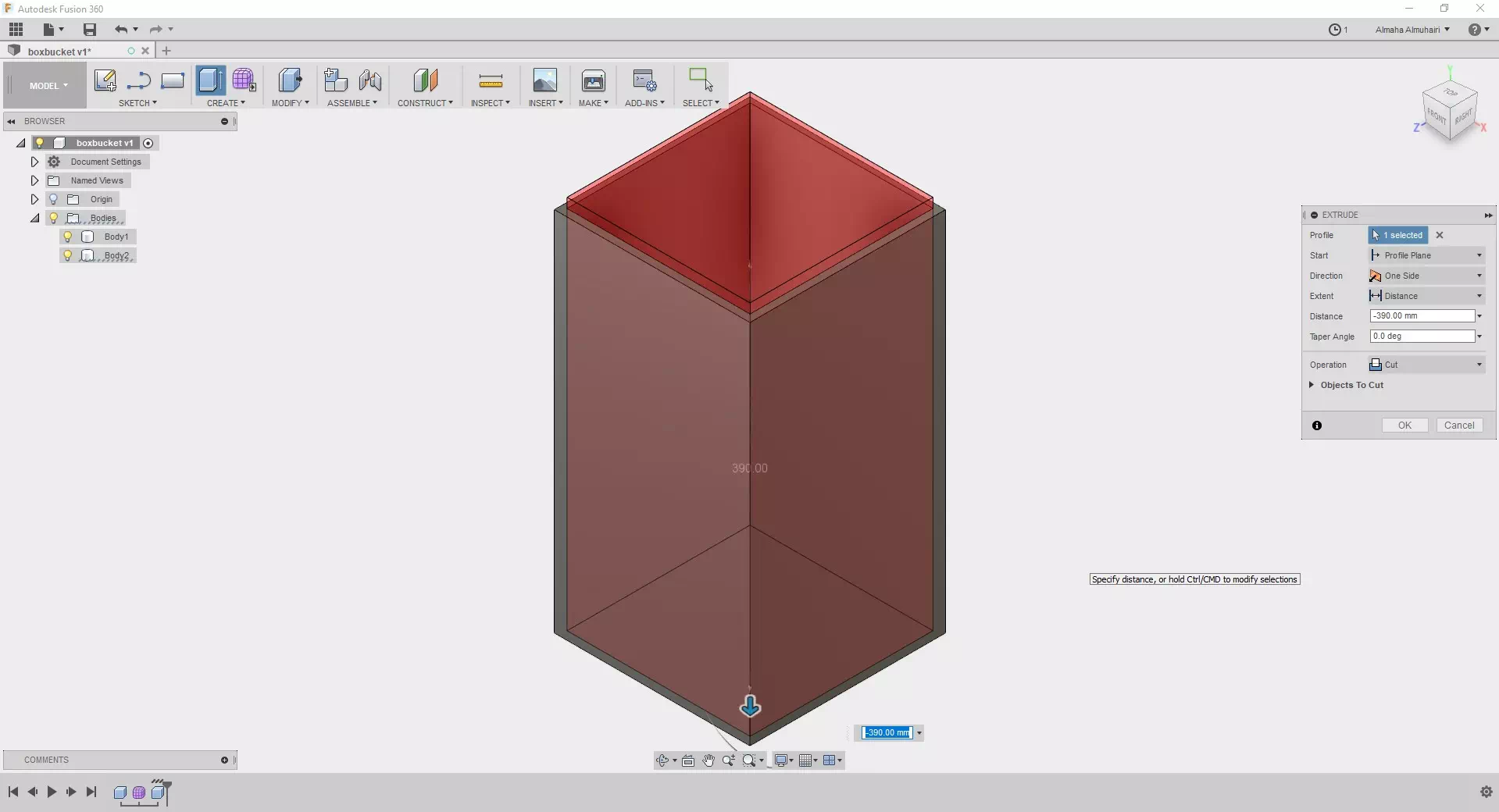
Still in the extrusion tab drag down the center arrow or adjust the distance to (-390mm) to create an empty pot.
The pot should look like this now.
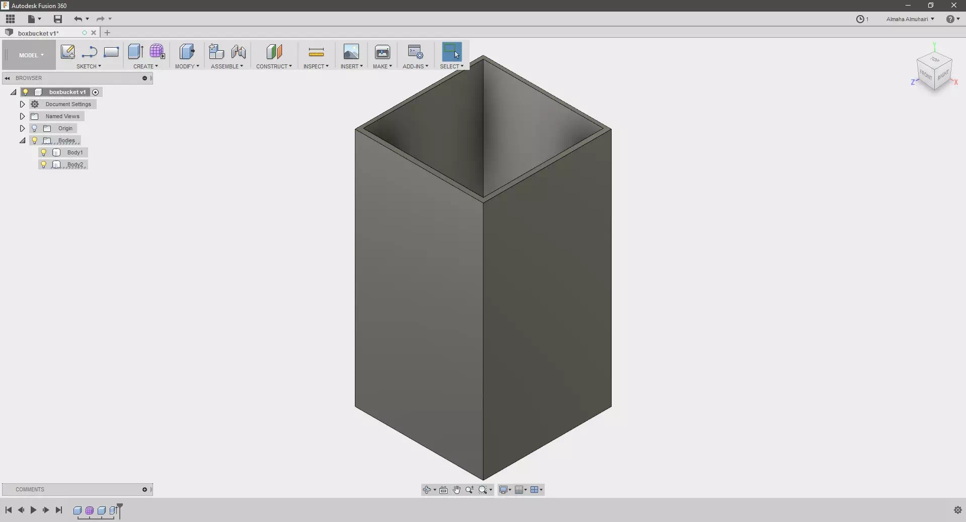
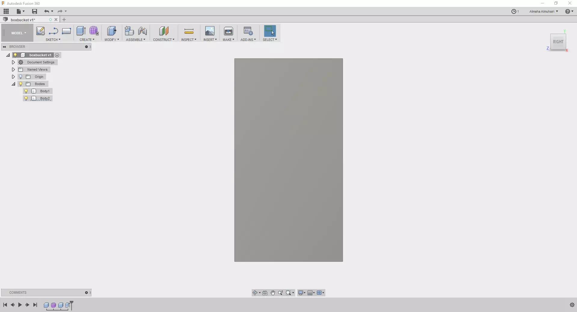
Pick one side (surface) of the pot to work on using the view dice on the upper right corner.
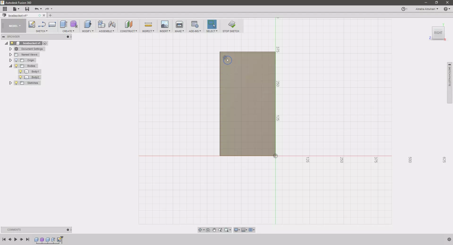
Create a sketch on the face, we created a center diameter circle of (30mm).
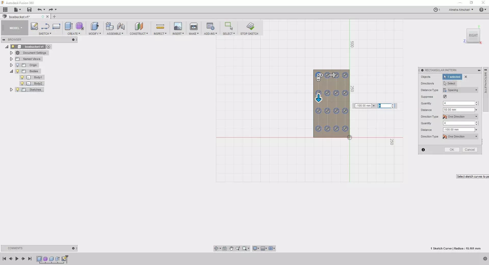
Click the circle sketch that you created on the surface and under the sketch tab click on the rectangular pattern tool, add your desired settings in our case we wanted to set the distance type to spacing and repeat the circle four times both directions.
Select all your circle sketches by holding down the shift key, then click the E key on your keyboard.
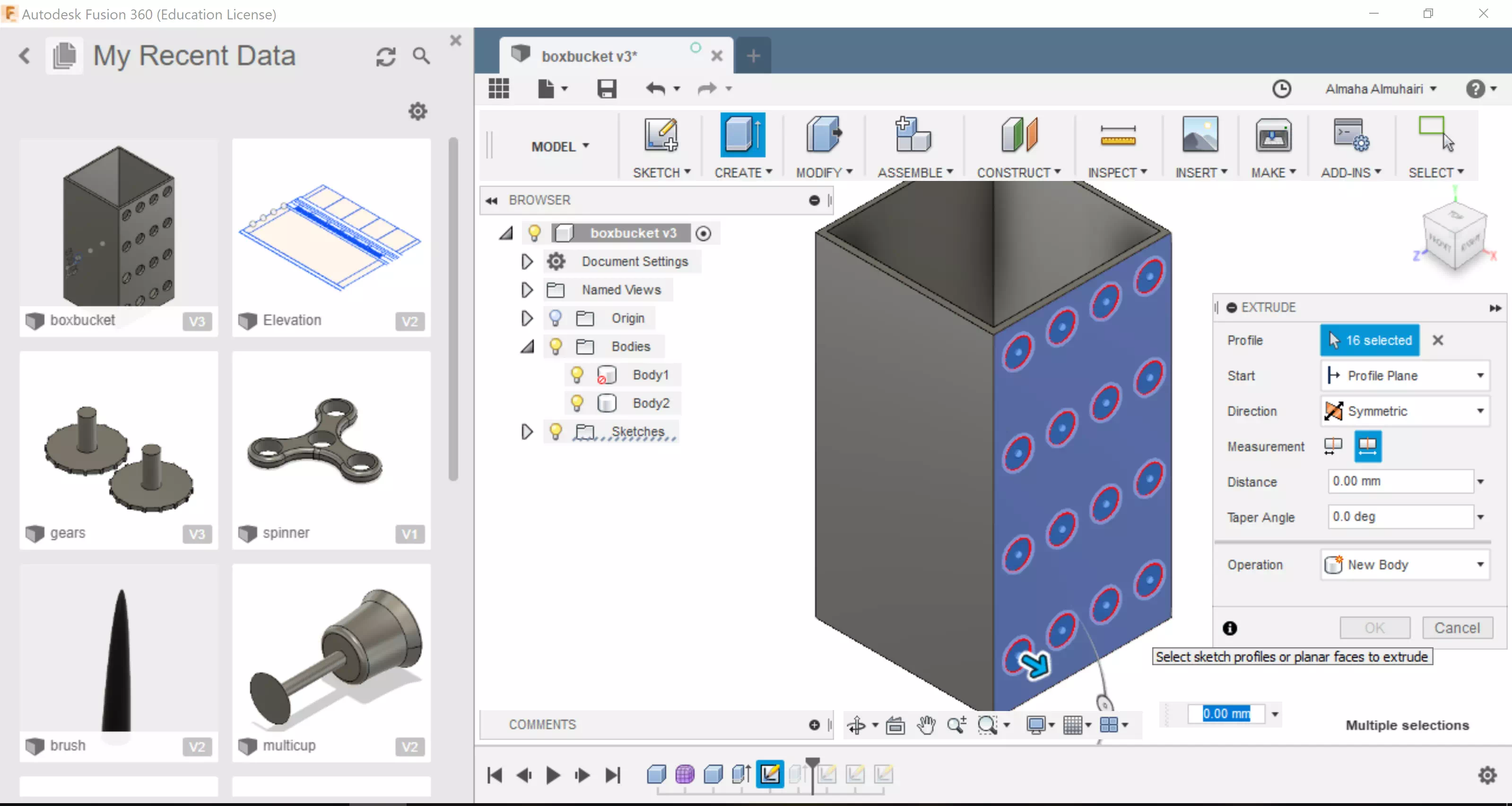
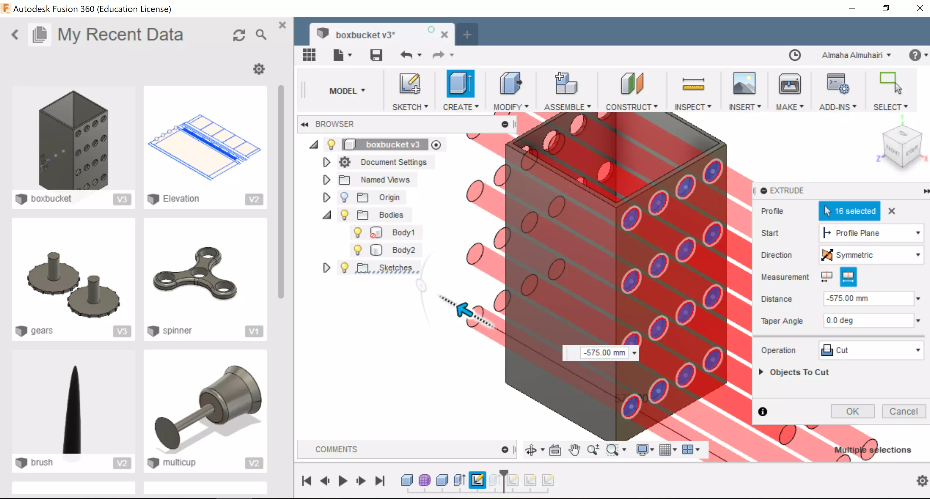
Still in the extrusion tab drag down (in the cut setting) the center arrow or adjust the distance to (-575mm) to create holes all the way through the other side.
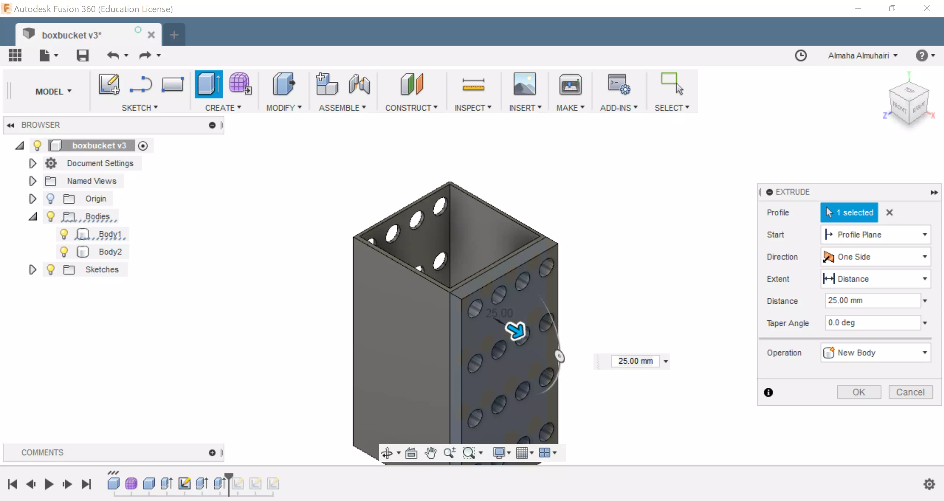
Find a surface with holes and extrude a new body over it, this body will be used as a pattern tool to recreate the holes on the other sides.
Right click on the new body, click on the "Move/Copy" command it, click on the rotation movement you can adjust the movement to 90 degrees.
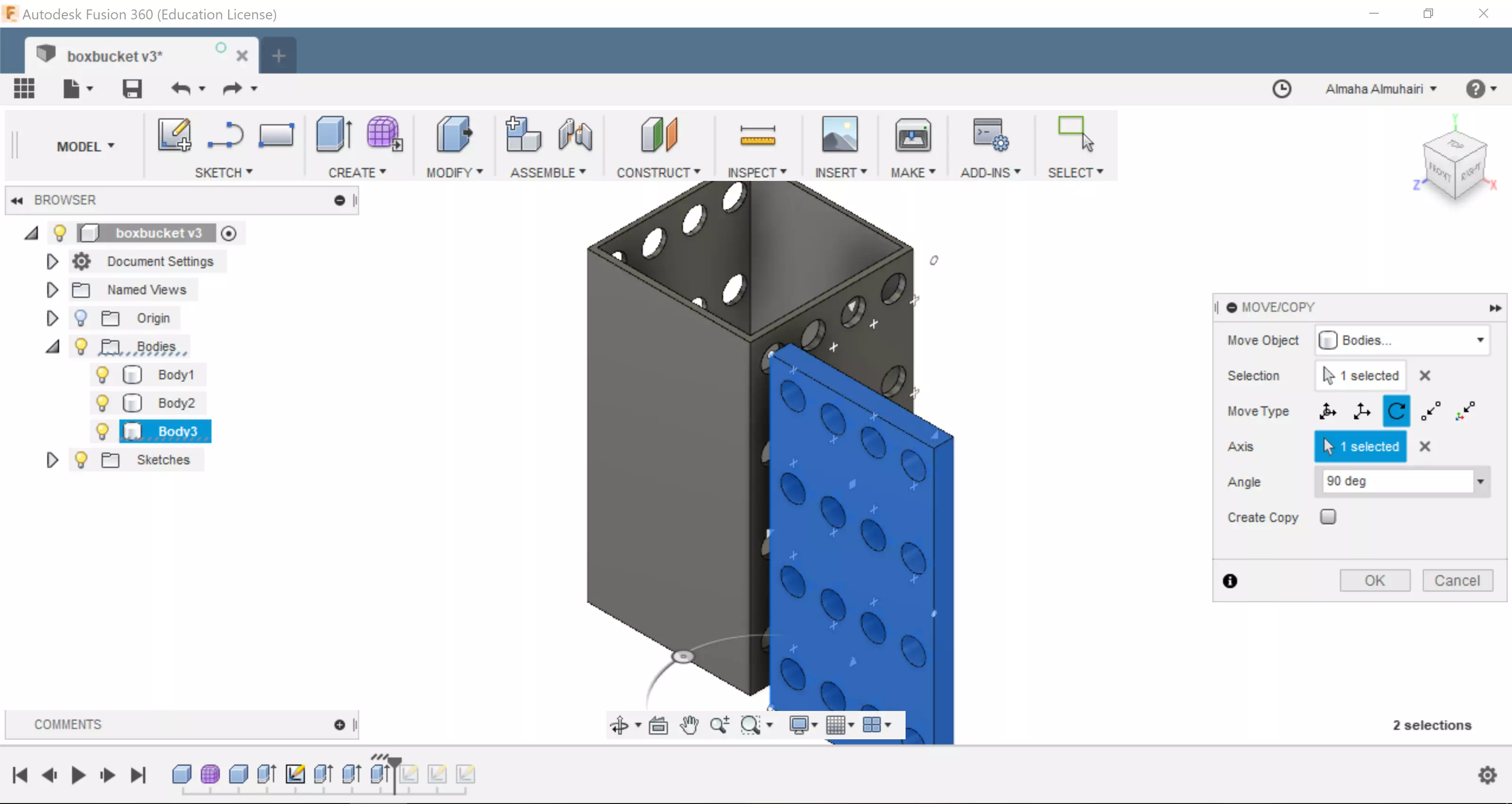
Using the free move options via the arrow keys can help you place the new body over the face.
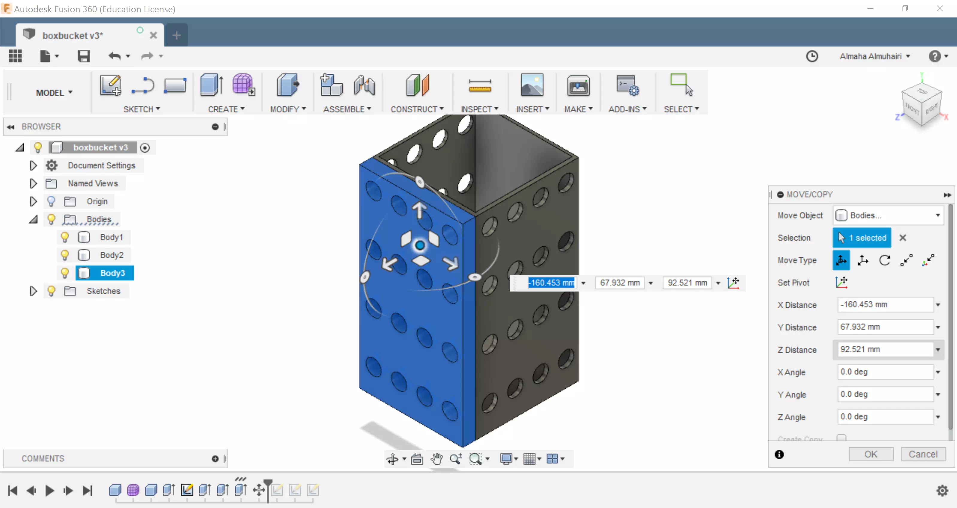
Click on the holes and extrude to cut negatively by dragging inwards.
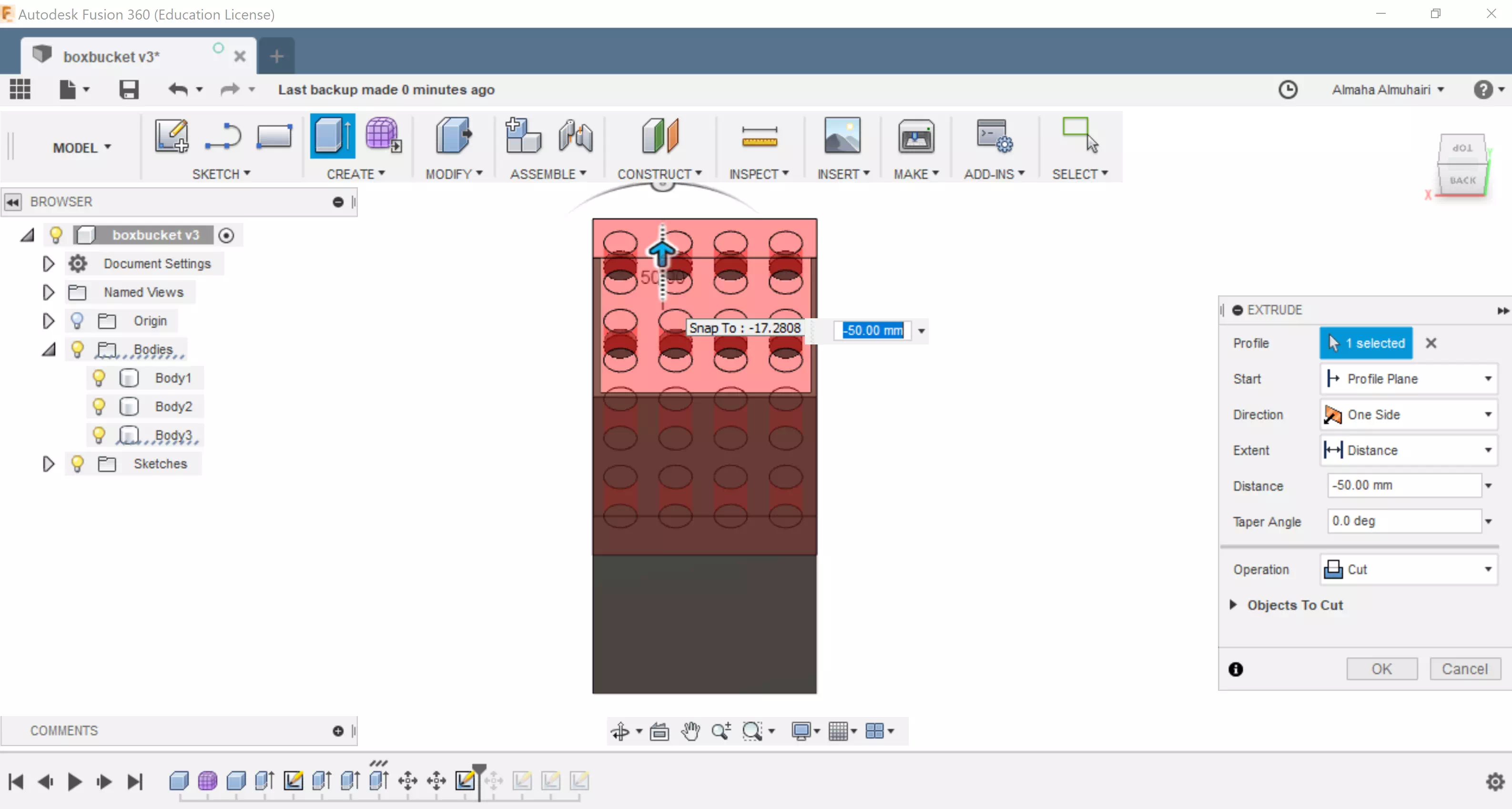
Keep Extruding the pattern till you reach the other side like steps before, after this you can delete the new body we had created (pattern tool).
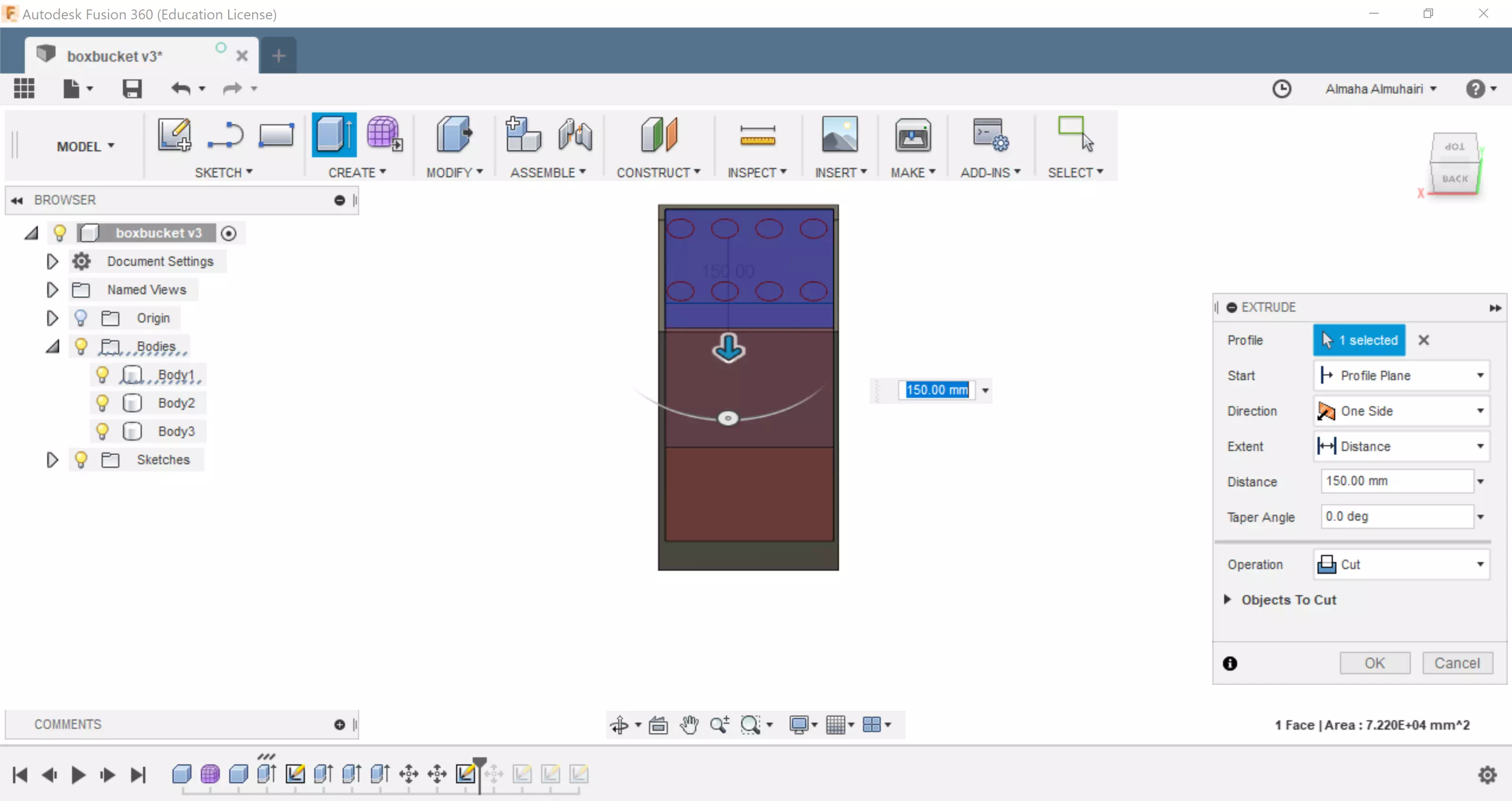
Your pot should look like this.
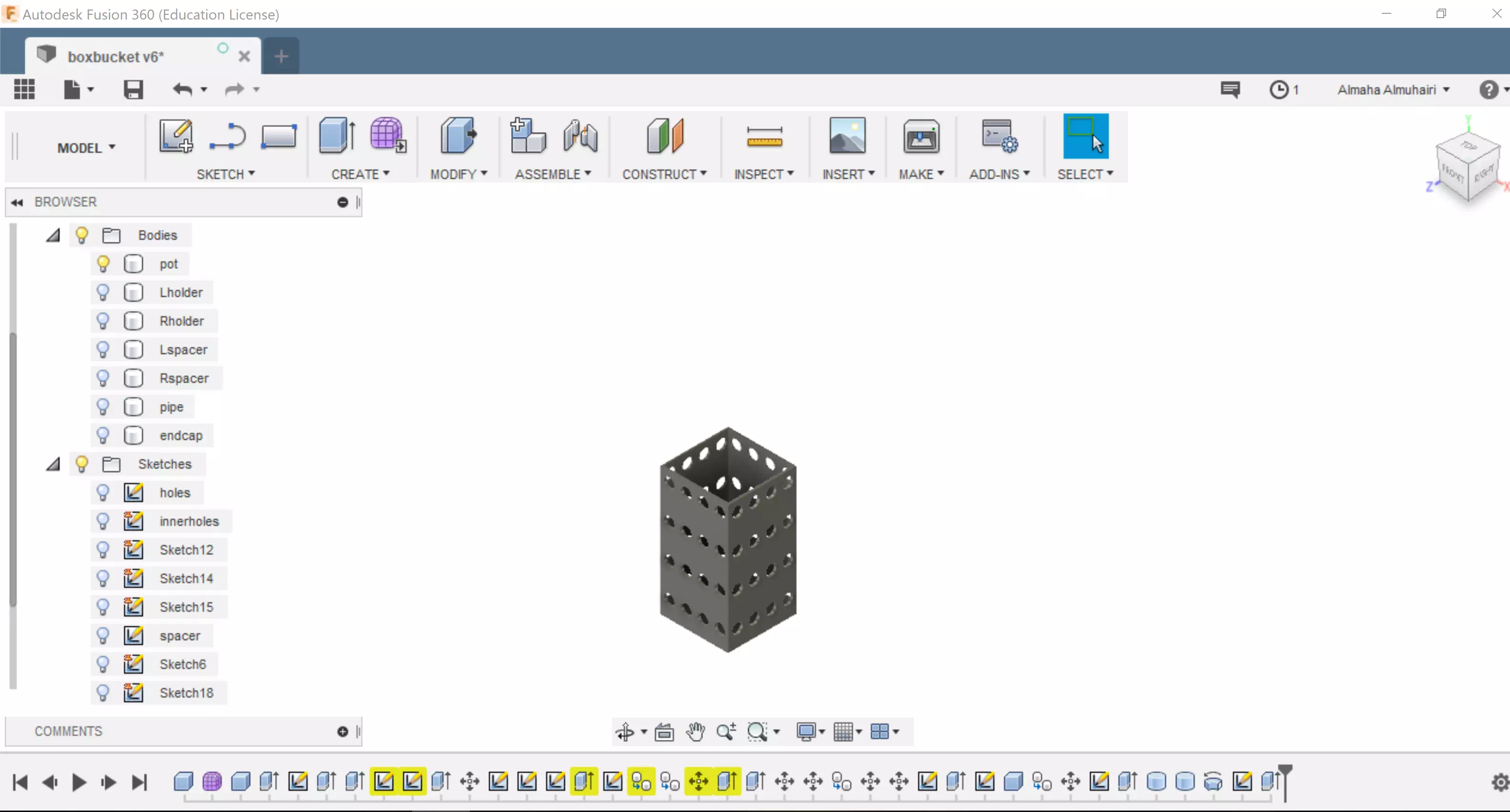
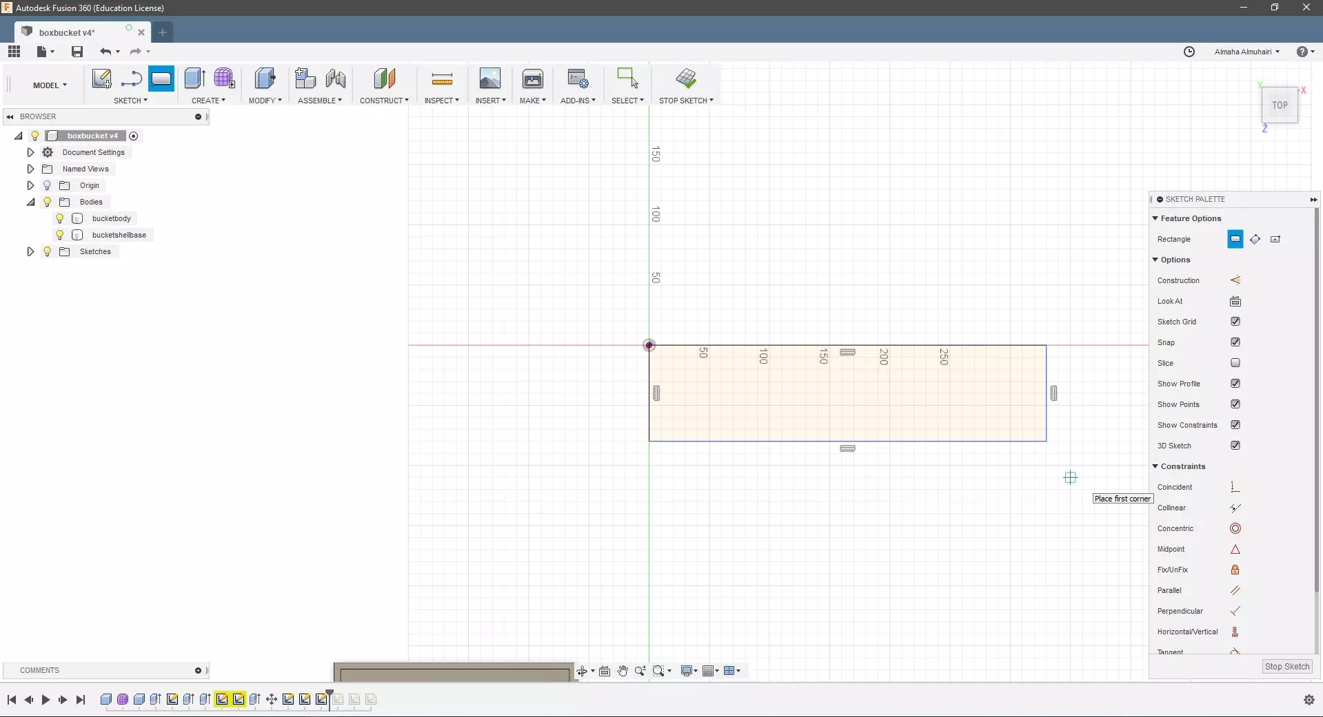
Create a sketch, start by creating a two point rectangle.
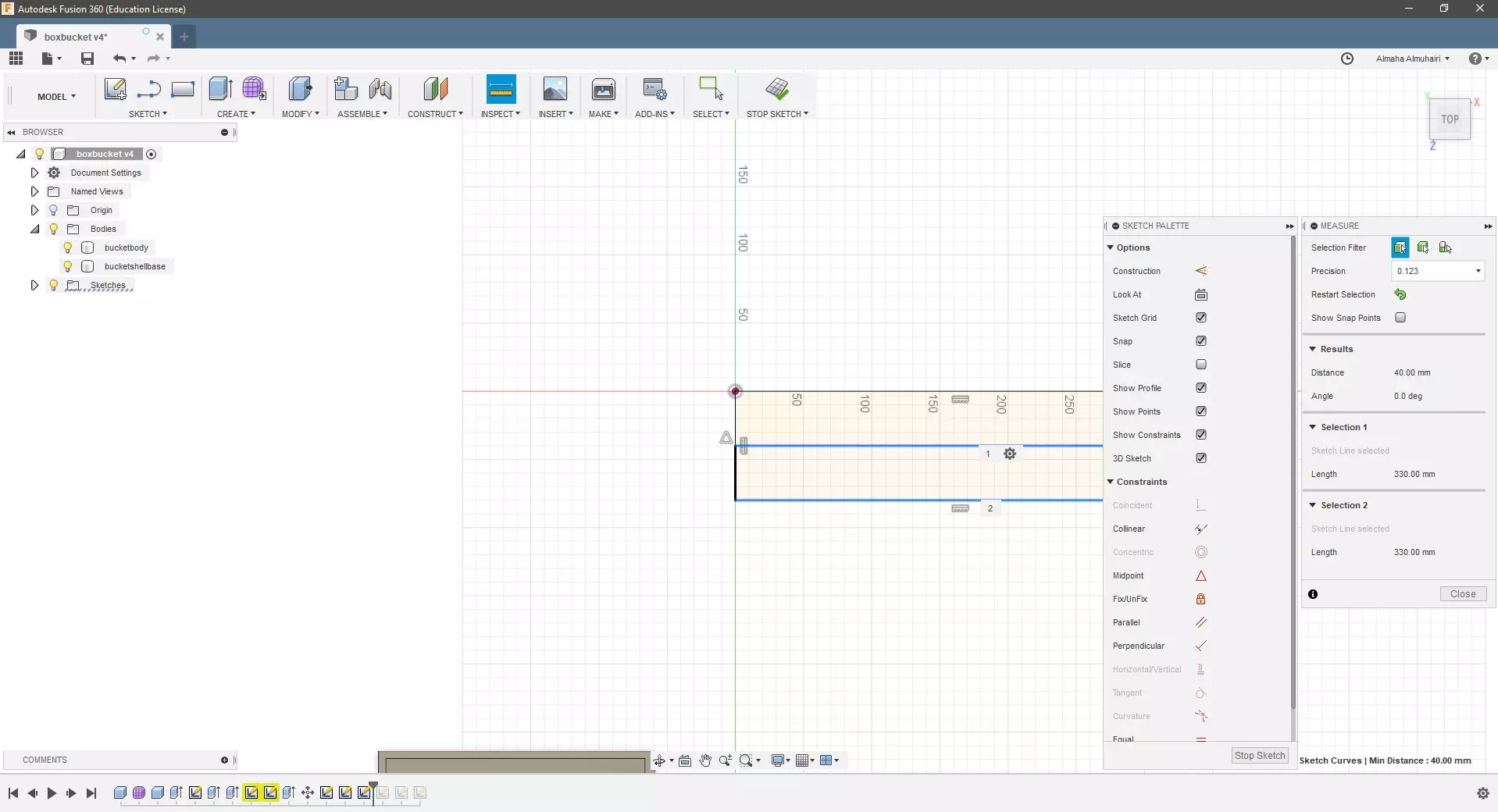
Using the inspection tool, find the midpoint of the rectangle we can use the constraints in the sketch palette for this. Or we can also use the measure tool, select the middle line and the outer rectangle line to see the equal distance to make sure it is exactly center. Then add a line using the sketch tool.
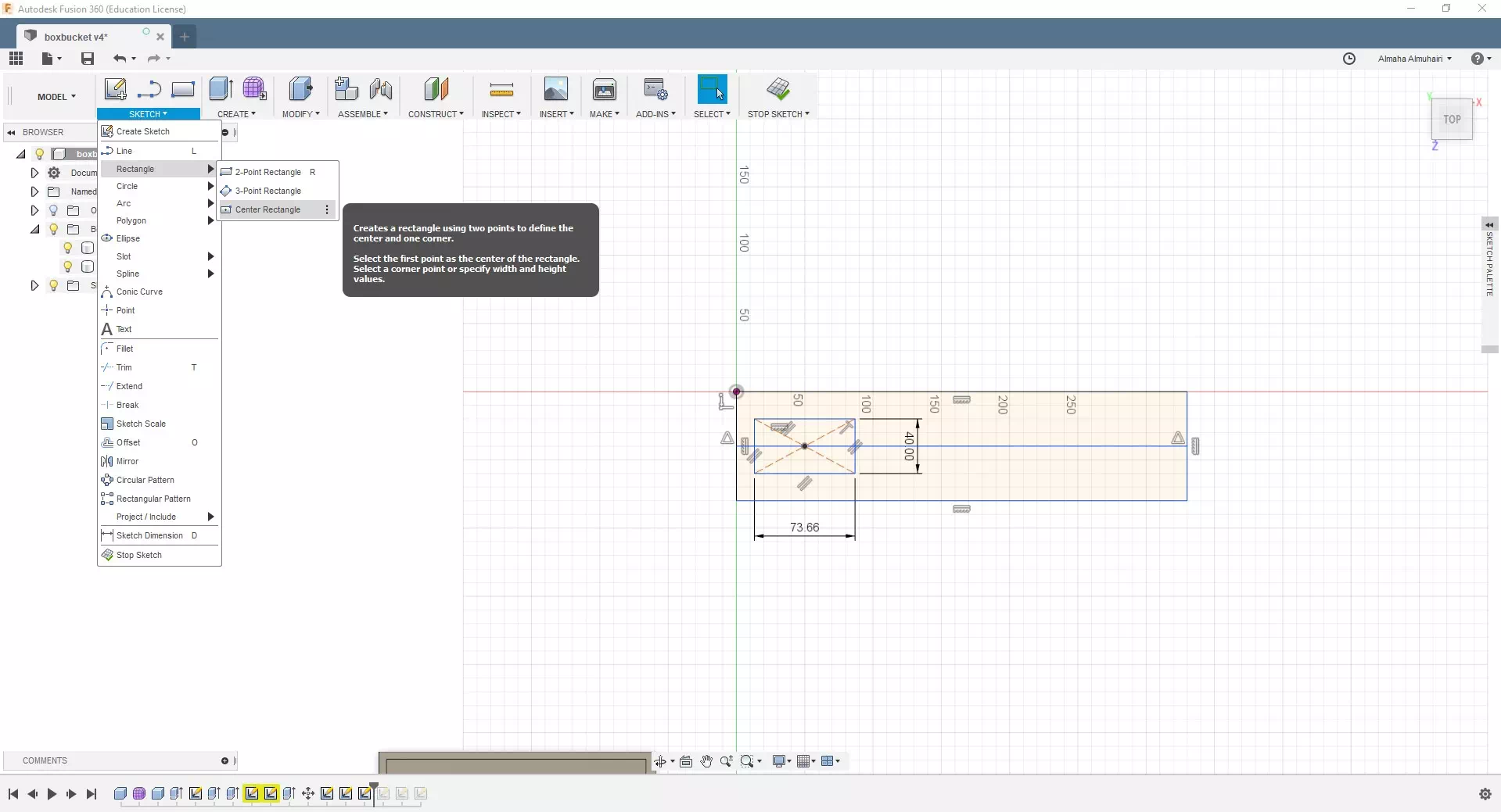
Create a sketch, create a center point rectangle.
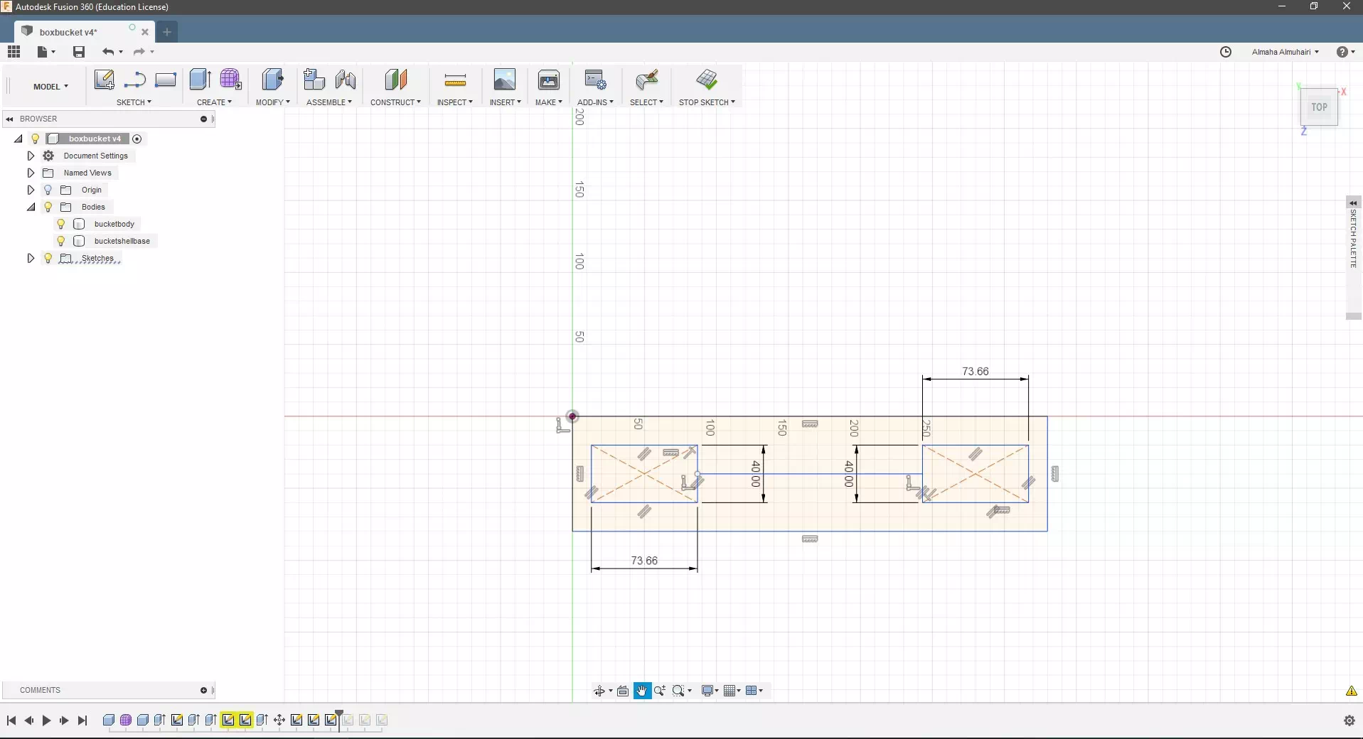
Make a copy of the center point rectangle and move it.
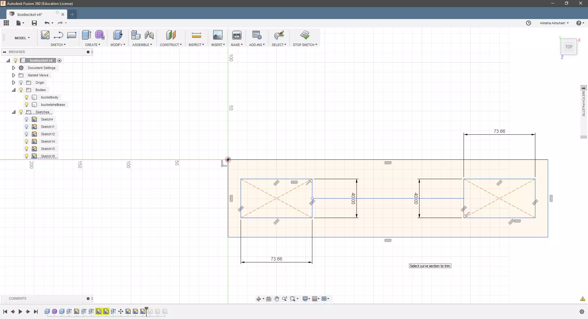
Using the trim tool remove the outer lines inside the rectangle.
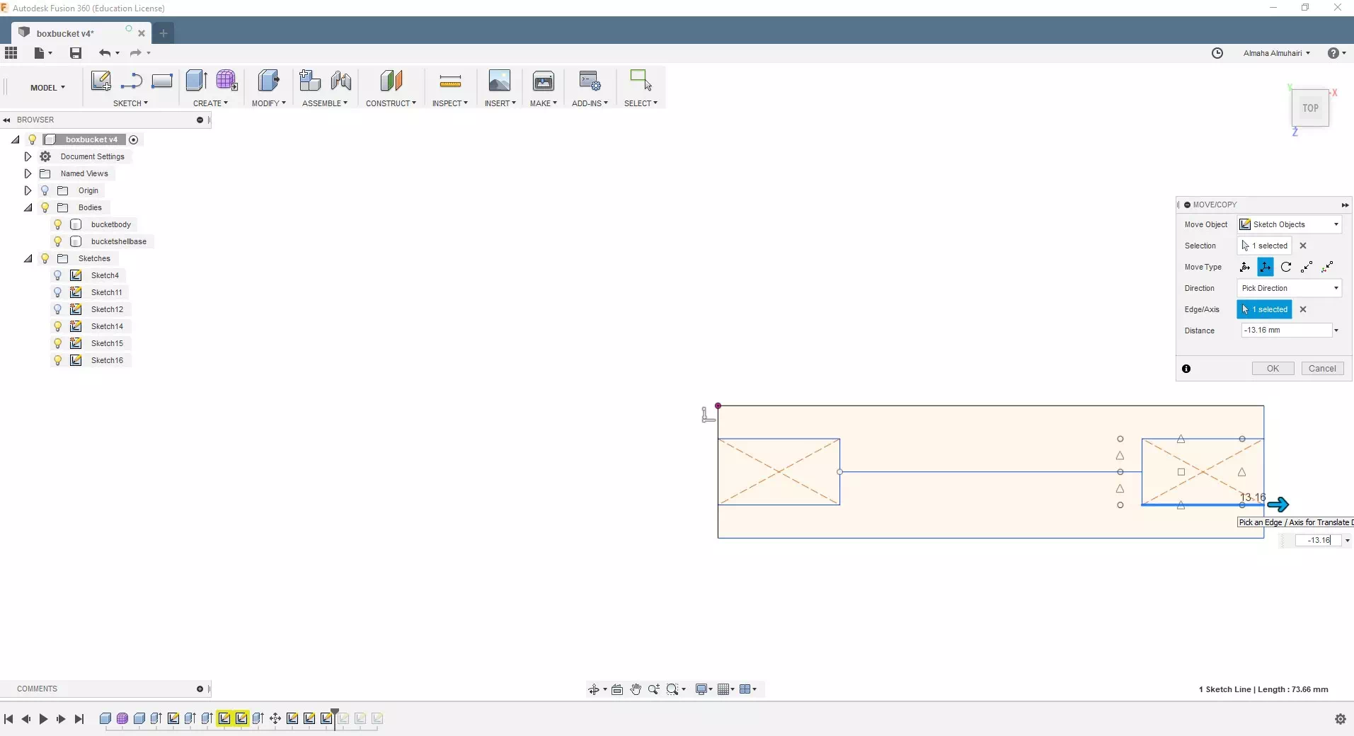
Using the move tool, move each rectangle to the edge of the surface.
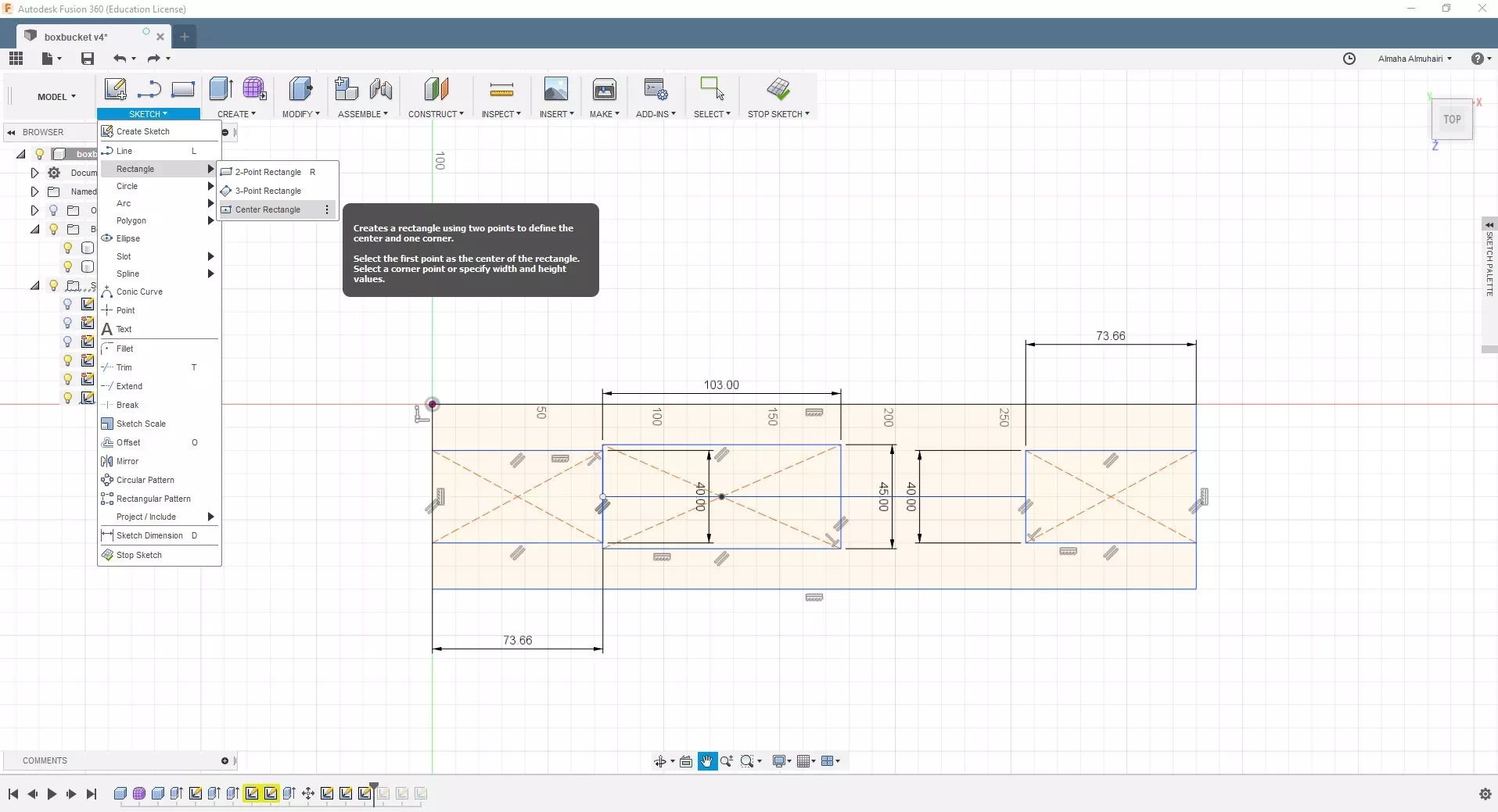
Create a sketch, create another center point rectangle, this time on the middle line.
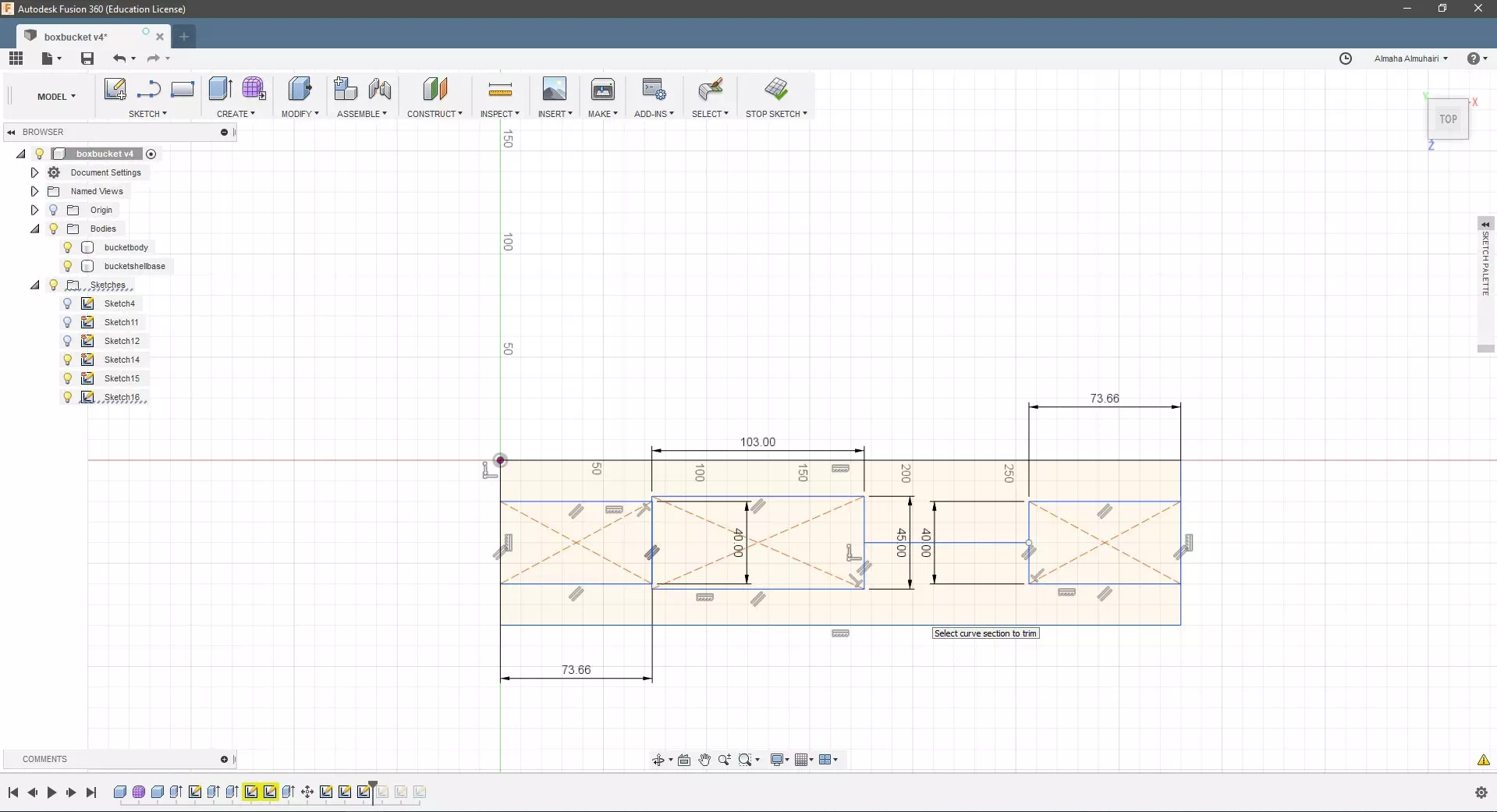
Your new center point rectangle should look like this, this piece is the spacer.
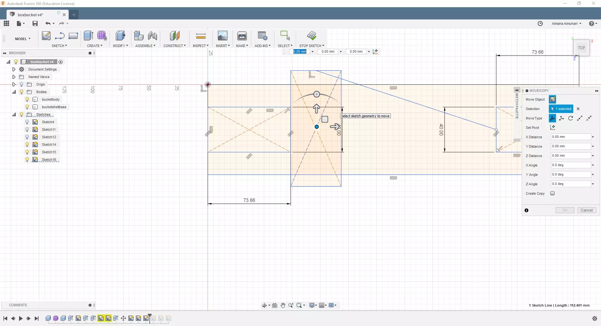
Using the move tool, move and rotate the spacer.
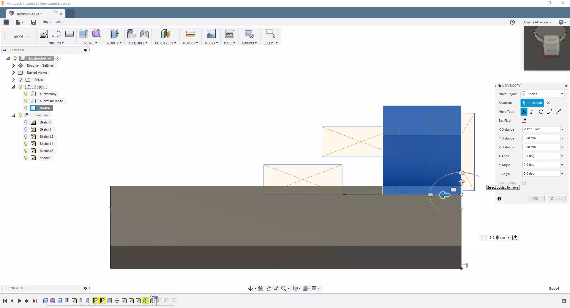
Extrude the bottom piece of the bracket along with the rectangle as a new body, then move it to its original position.
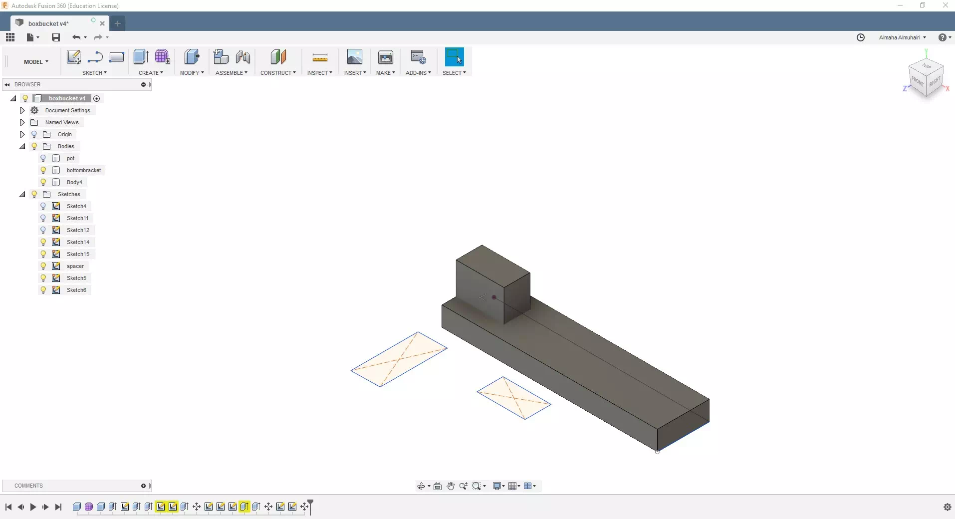
It should look like this.
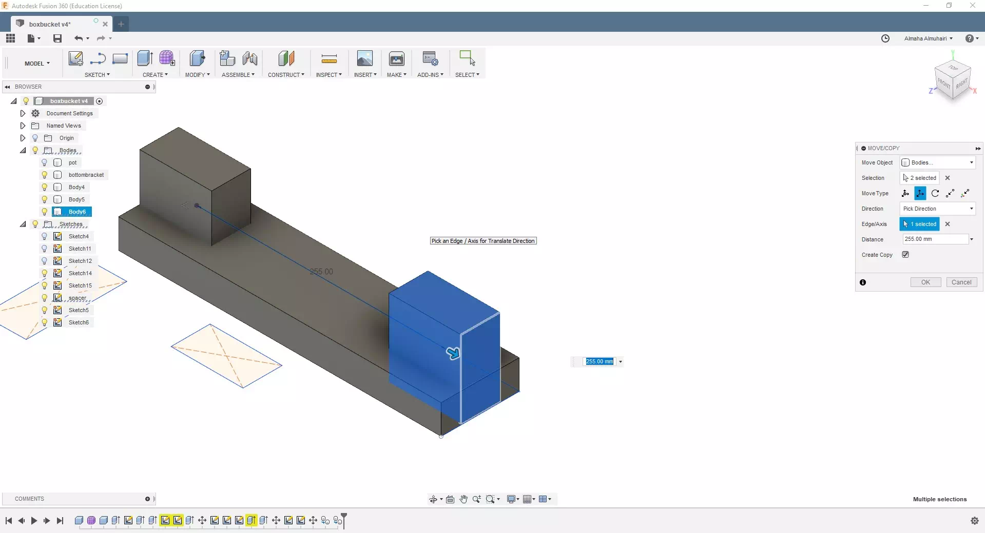
Make a copy of the extruded center point rectangle and move and copy it to the other side.
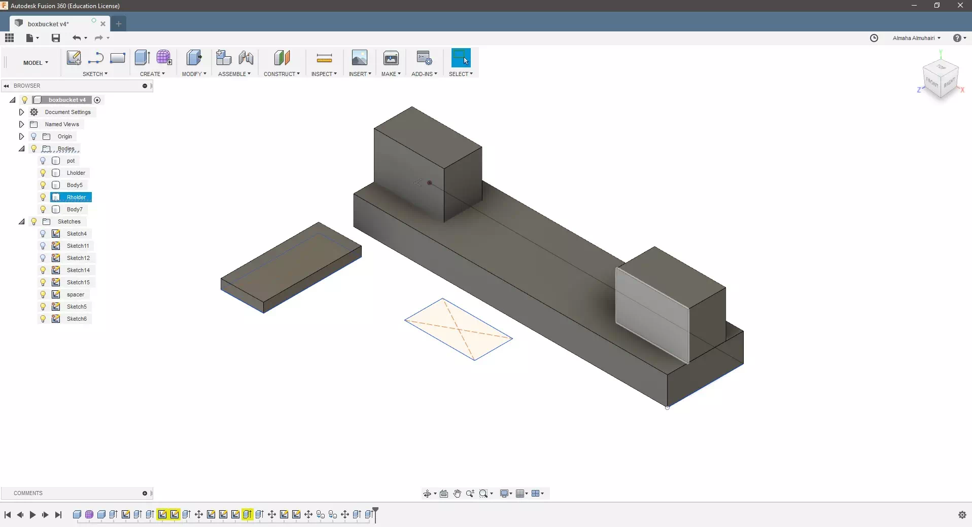
Extrude the spacer.
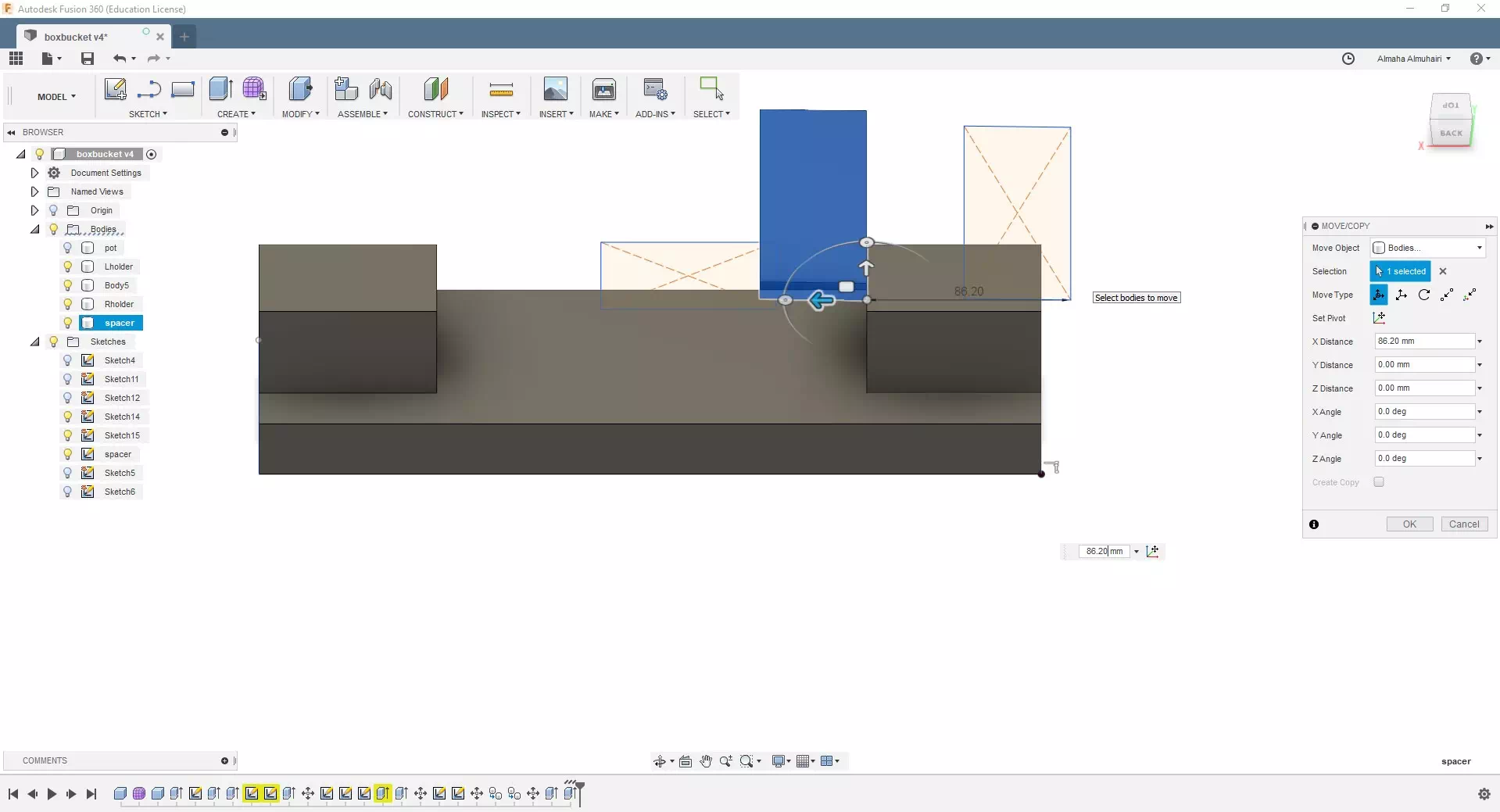
Using the move tool, move the spacer vertically.
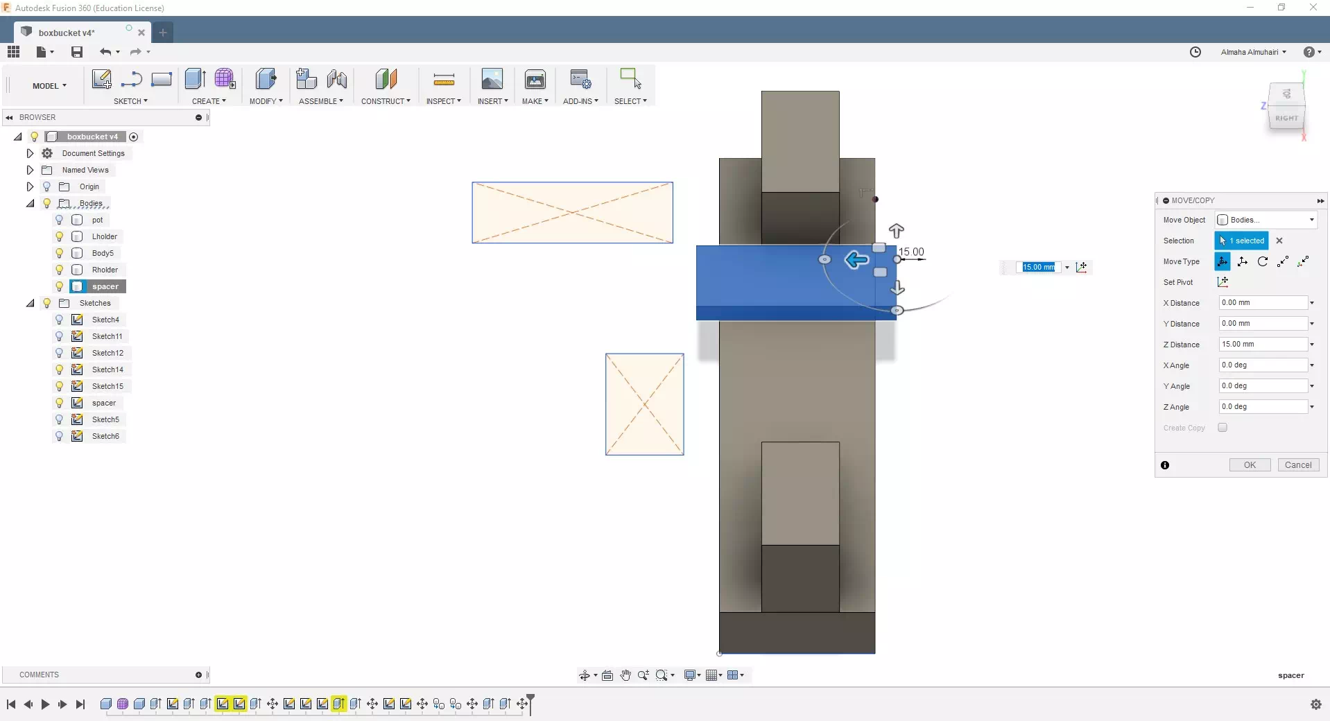
Still in the move tool move the spacer horizontally and place it on the bottom surface.
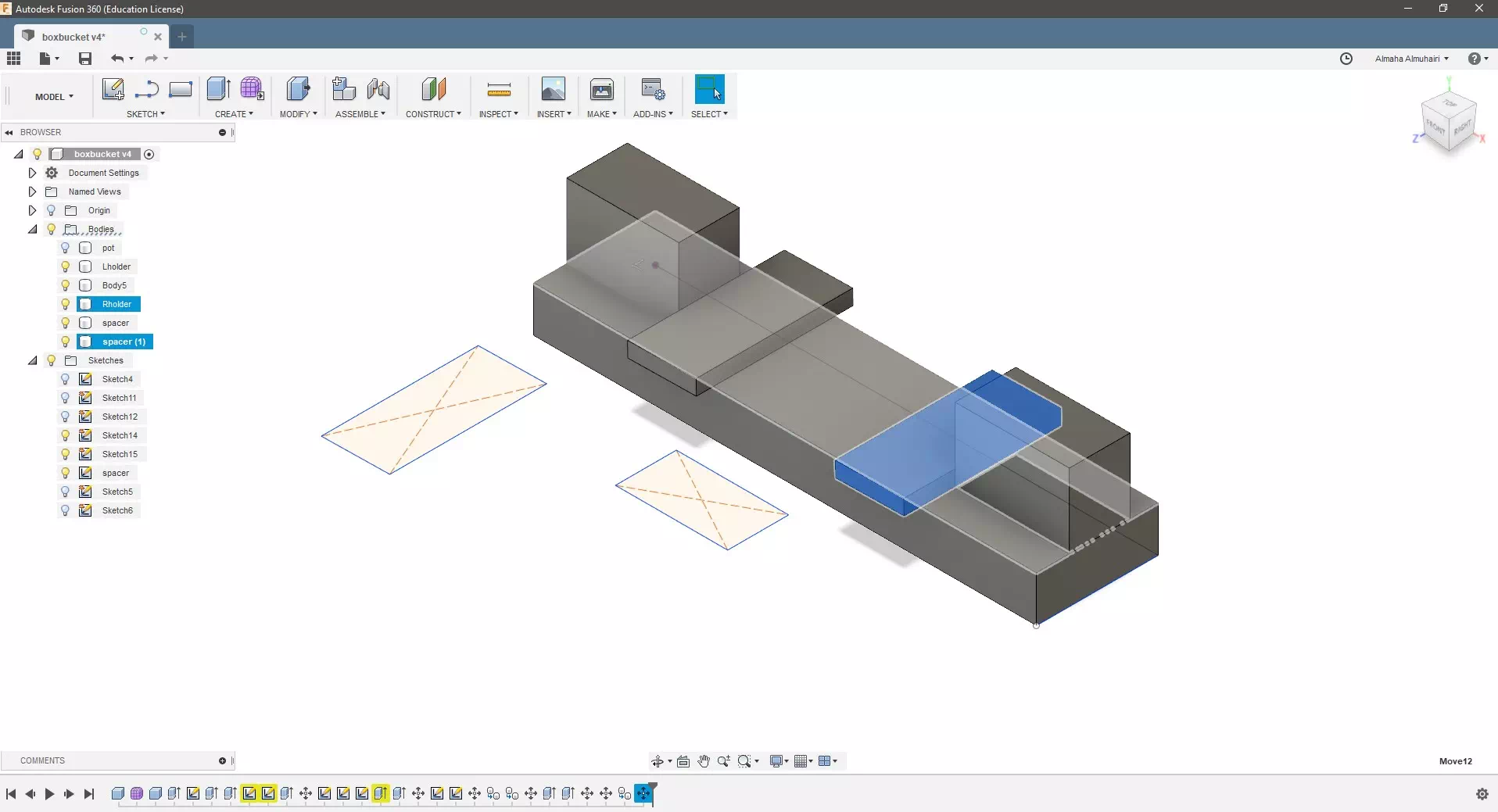
The bracket is done and should look like this.
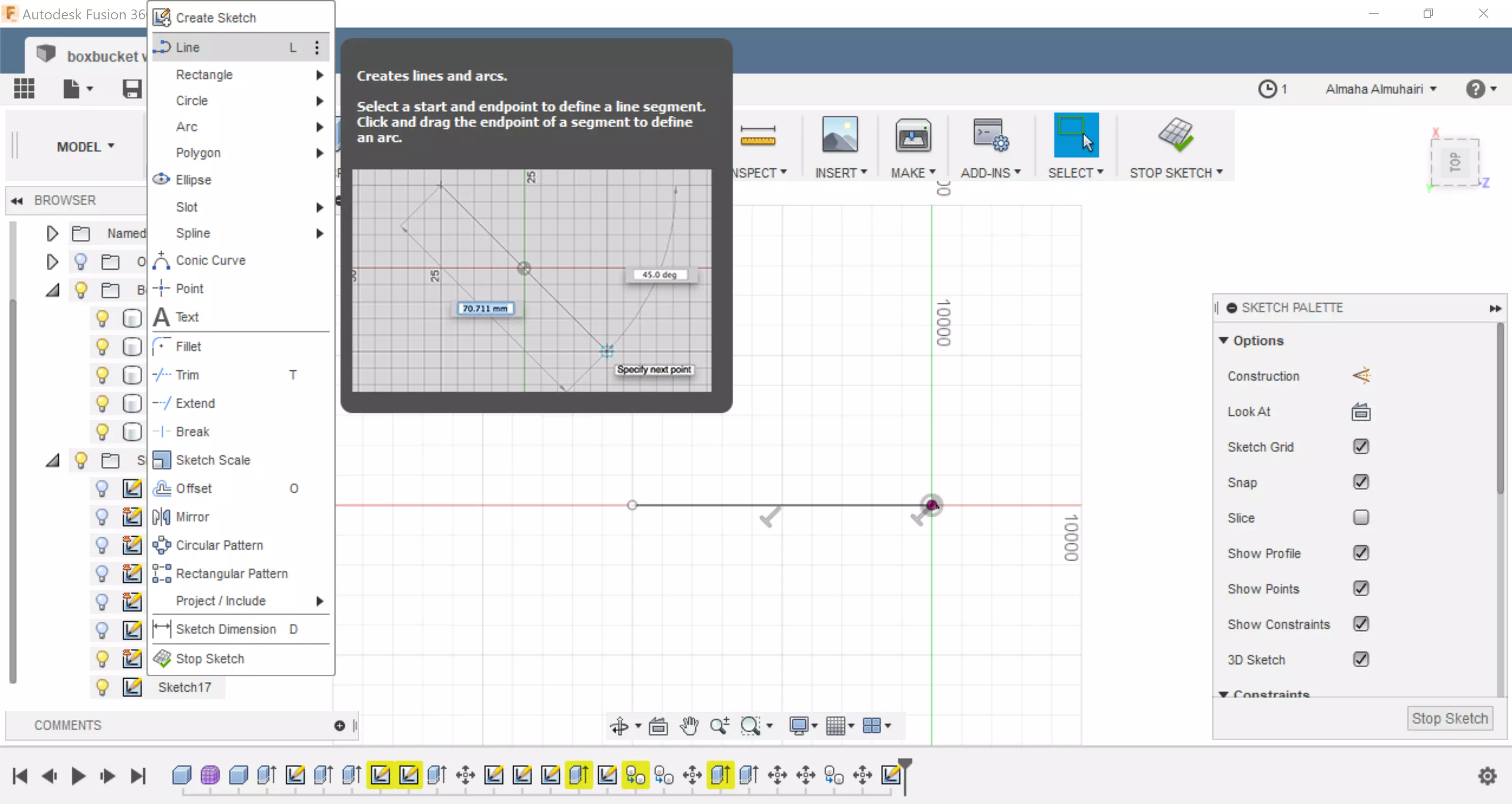
Using the sketch tool, create a line.
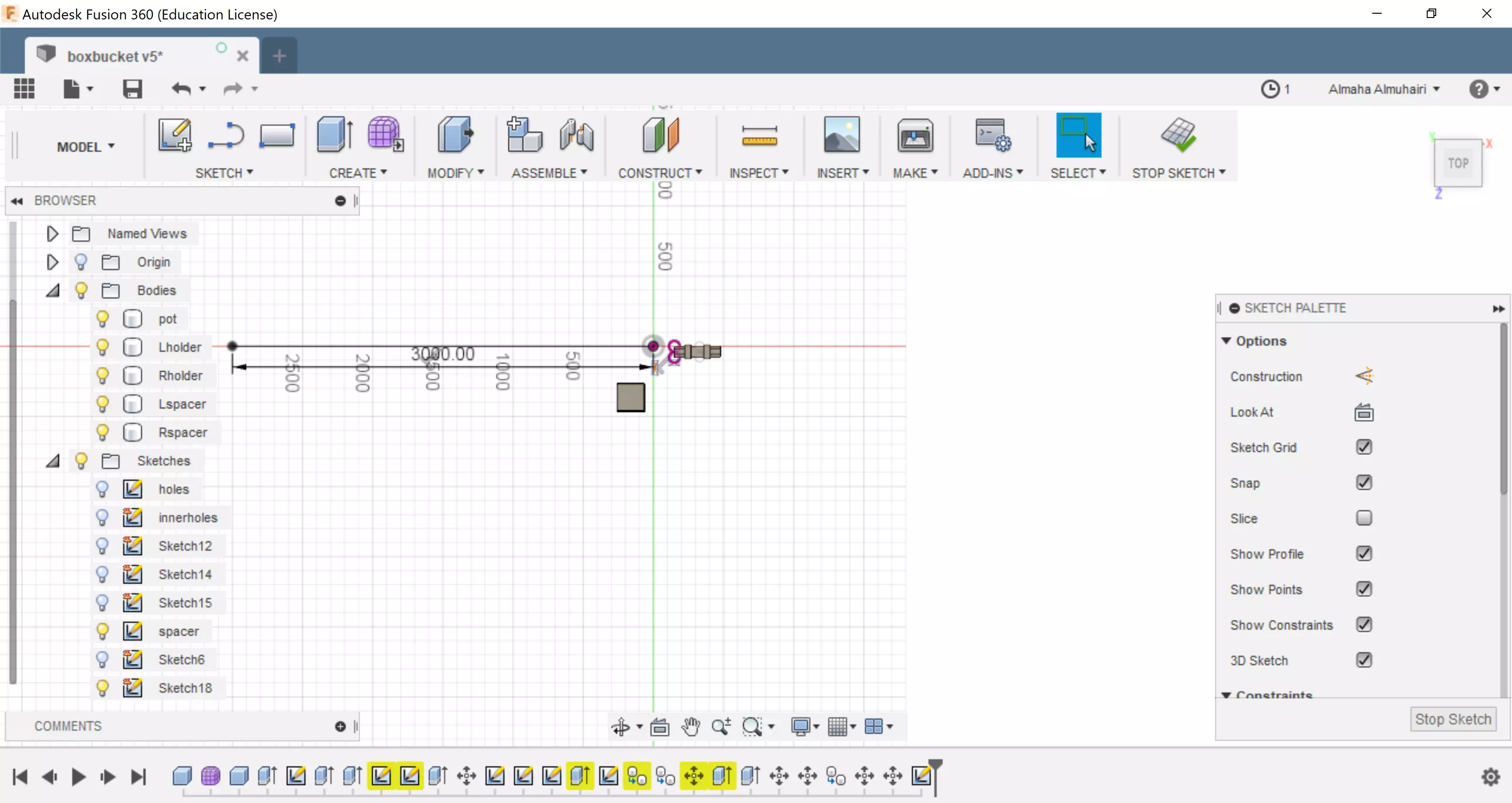
Using the sketch tool, create another line on top of the first line maintaining a distance, use the sketch pallette to assist you.
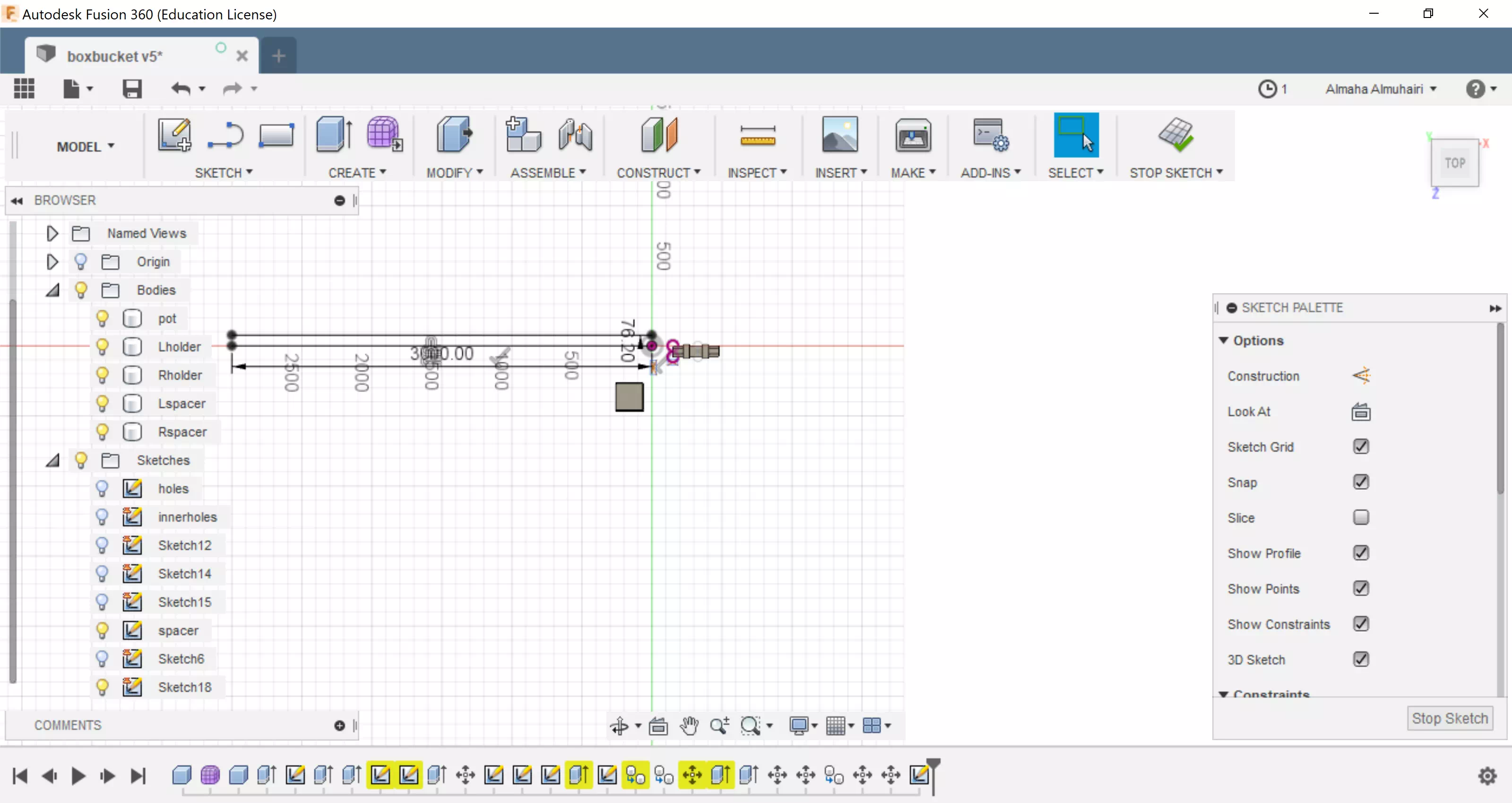
Using the sketch tool, create a line to join the two end corners, you will create two lines to connect each two end dots.
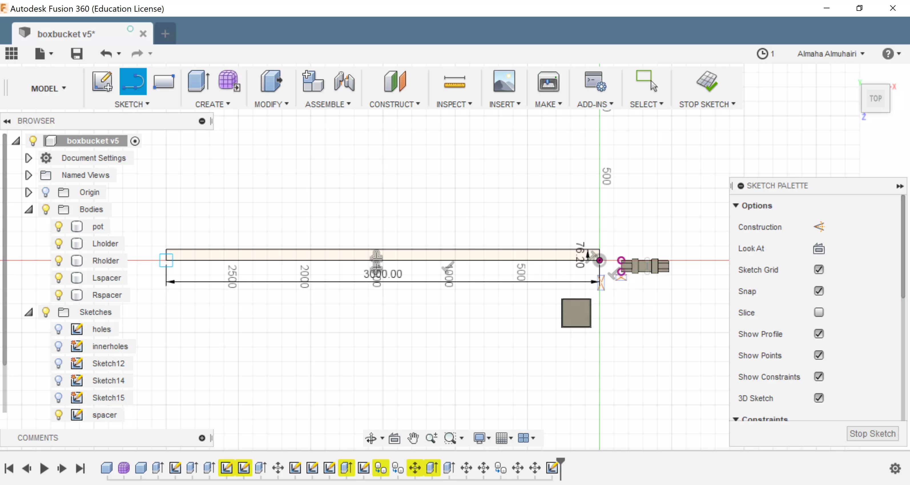
After you connect the lines on each corner your rectangle should look this.
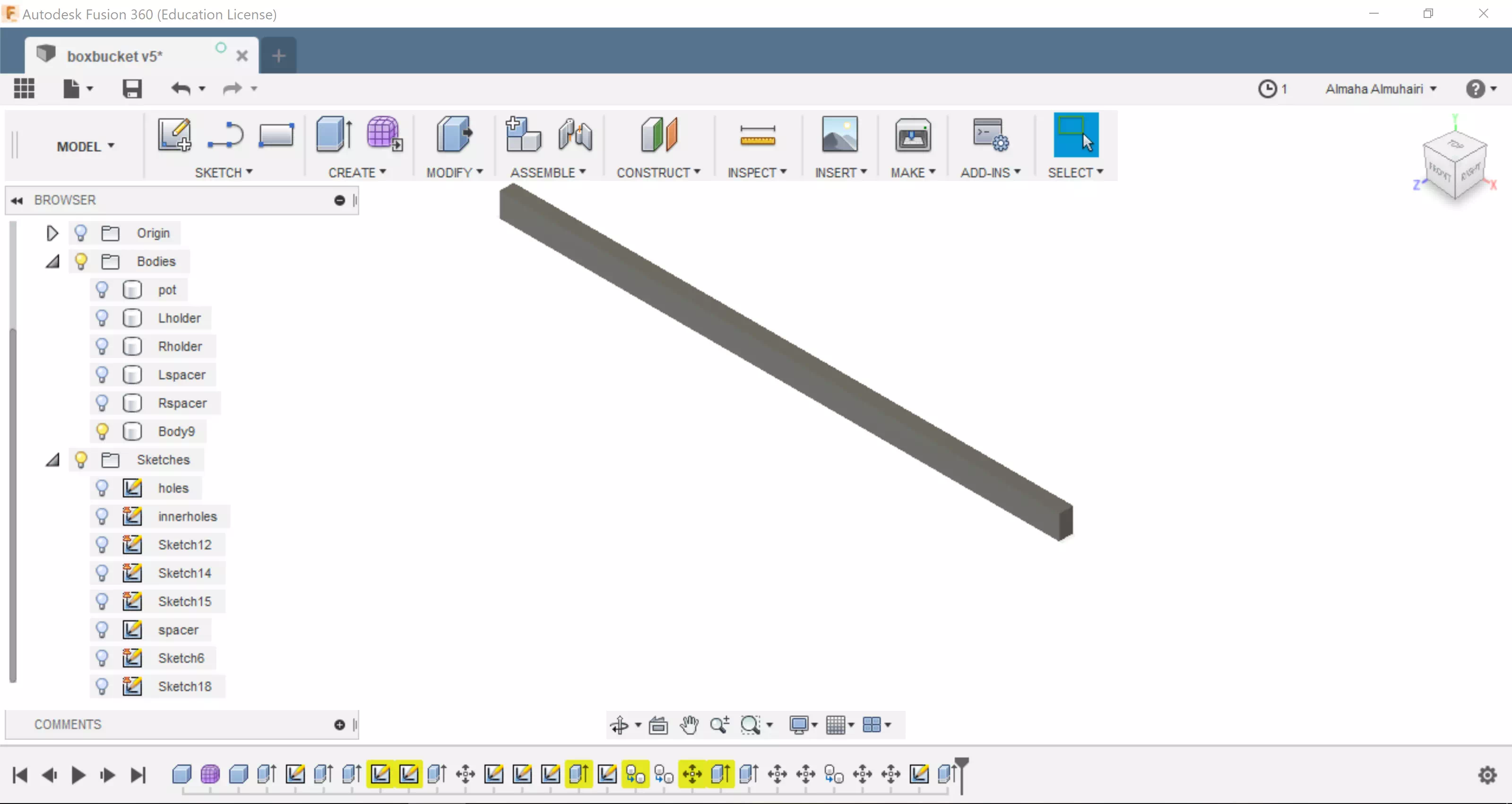
Extrude the rectangle as a new body.
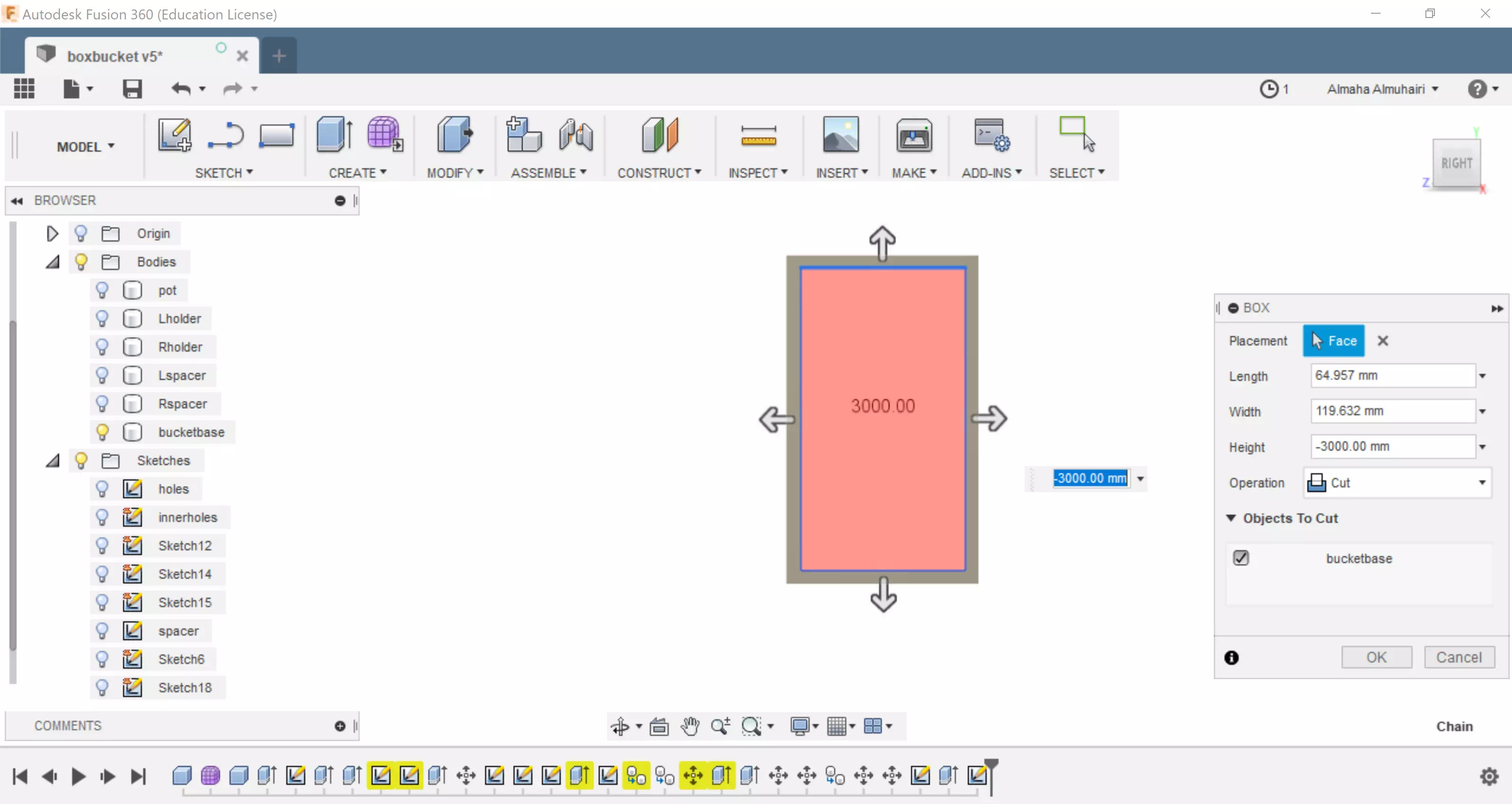
Using the create tool create a box inside the face of the rectangle and set the operation to cut through the entire length of the new body in our case it is (-3000mm).
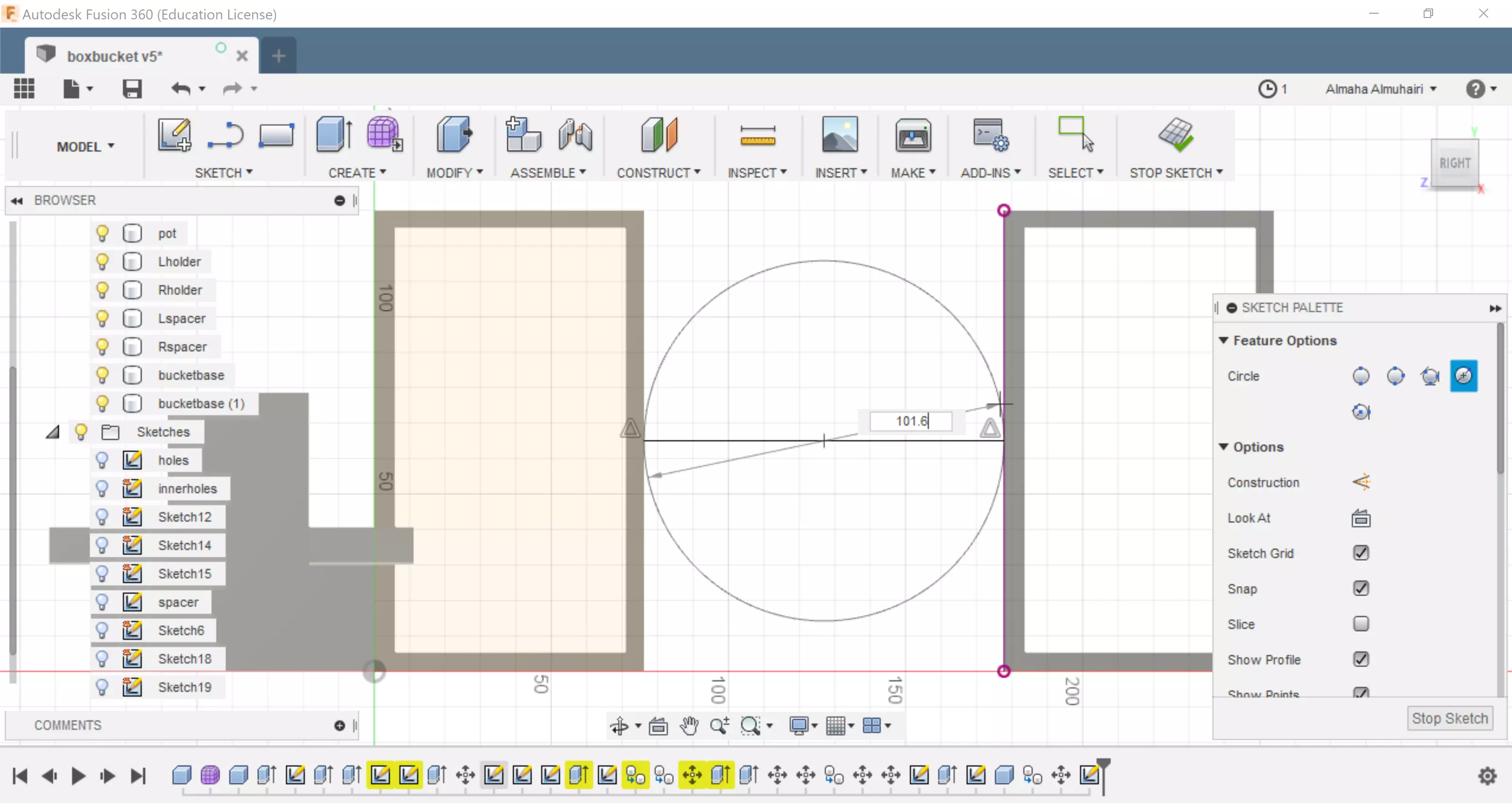
Move and create a copy of the extruded rectangle, then sketch a line between the two rectangles, then sketch a center point circle in the center of the rectangles, using the constraints to assist you.
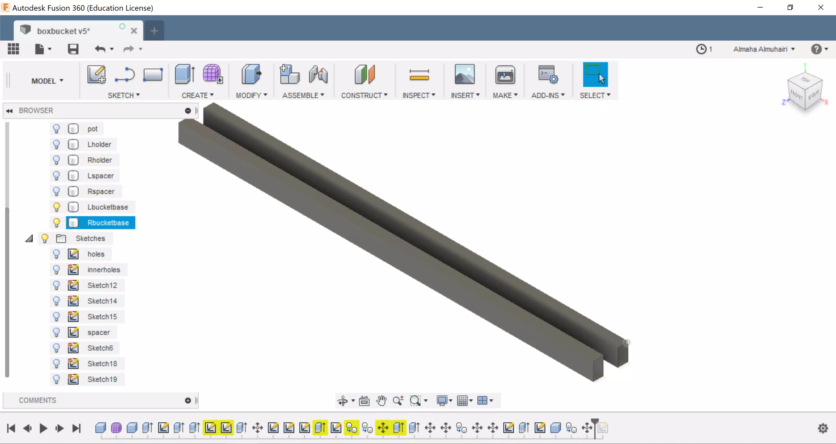
After exruding both rectangles it should look like this, this will function as the buckets base, or the buckets holder.
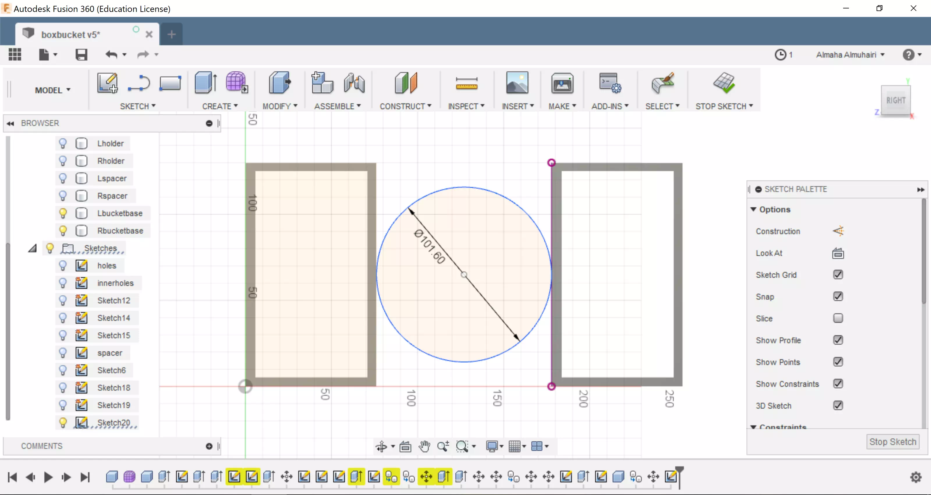
After creating the middle circle it should look like this, this will be your pipe.
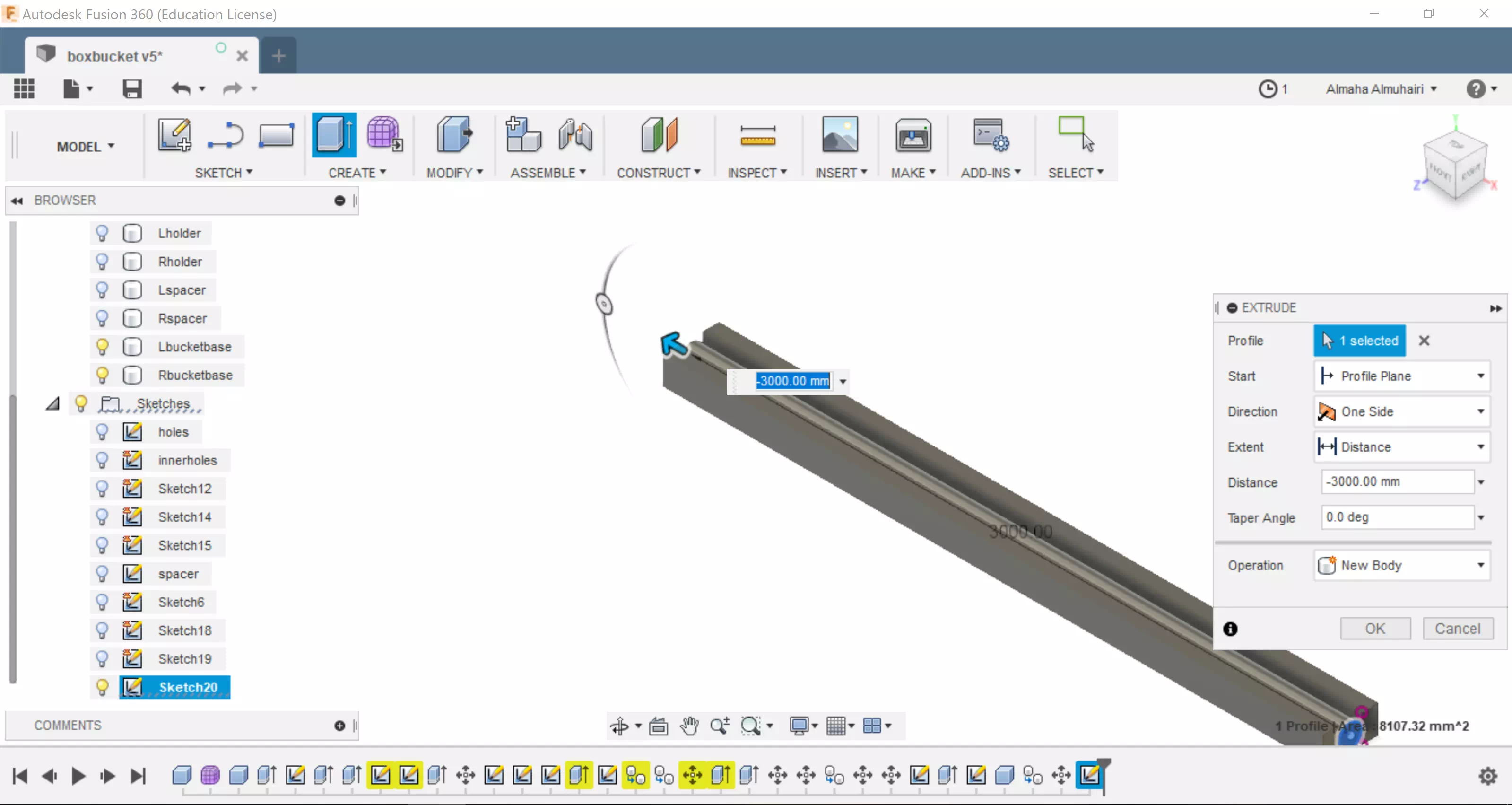
Extrude the circle between the rectangles as a new body. This is your pipe.
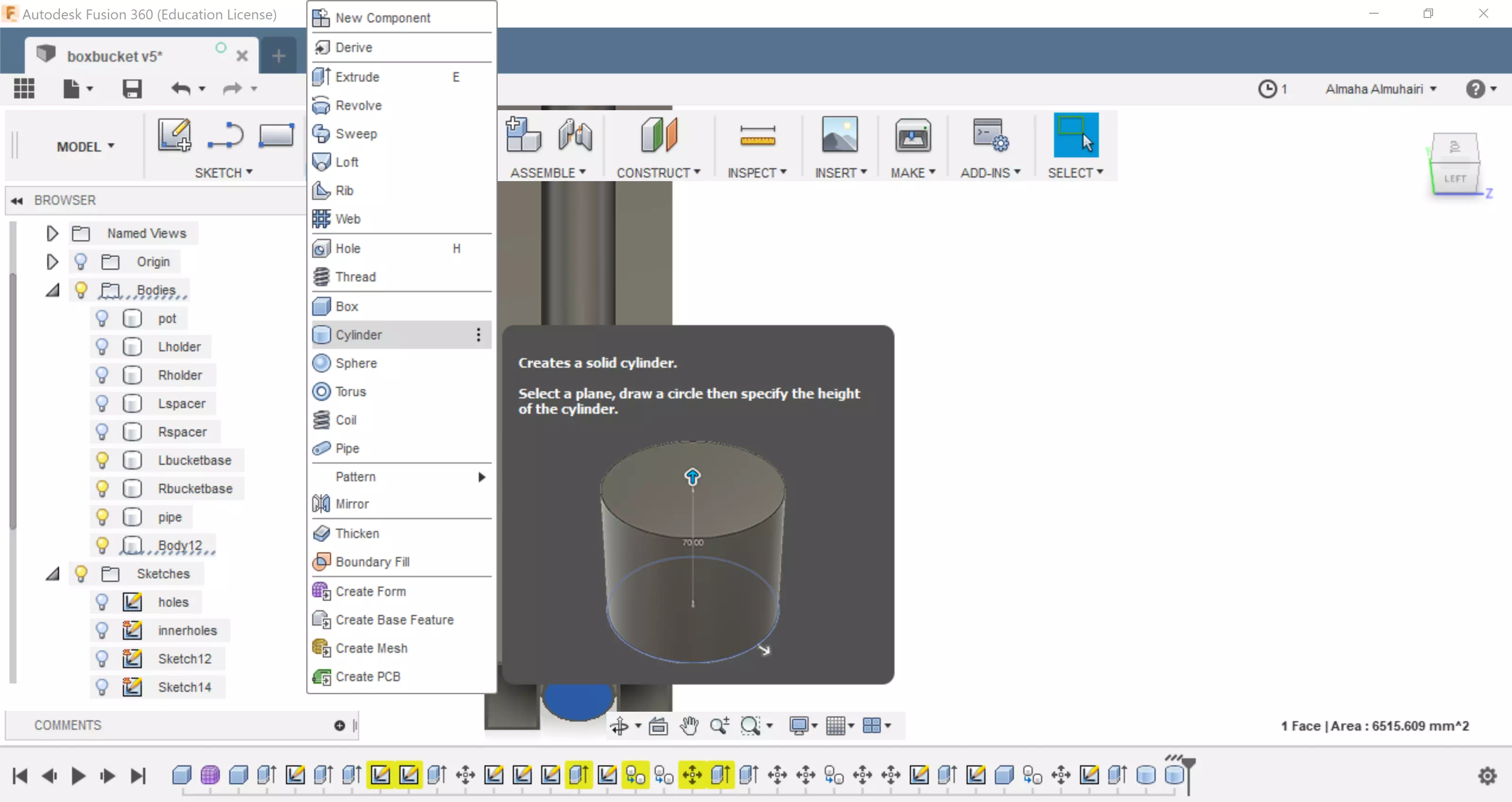
Create a cylinder inside the face of the pipe.
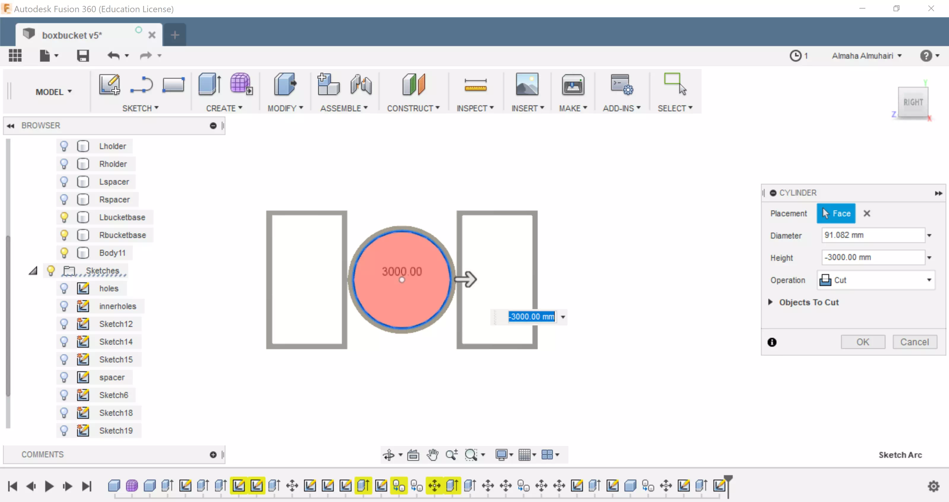
Using the Cut operation in the cylinder cut the inside of the pipe to (-3000mm).
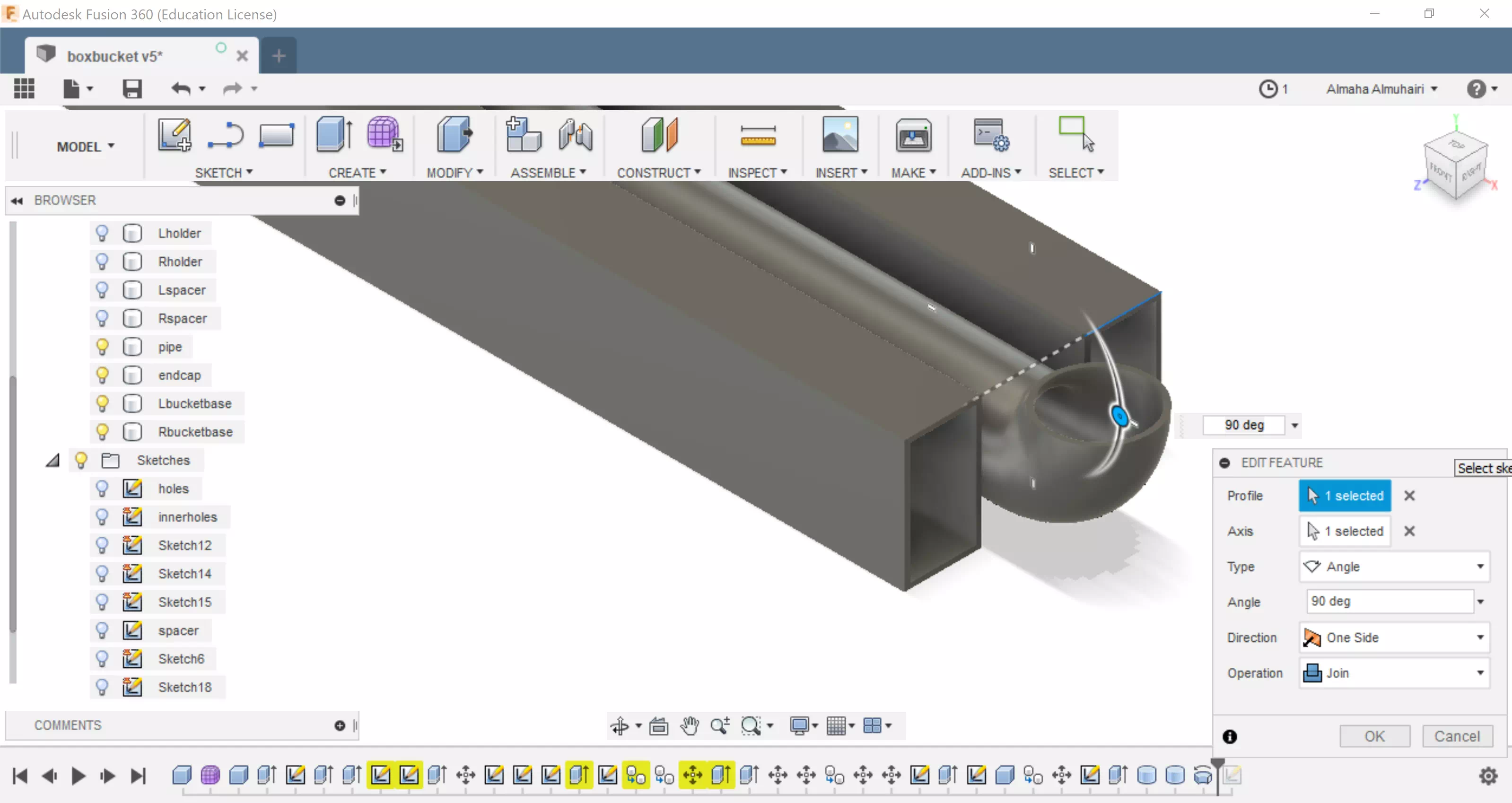
Lets create the water spout, using the revolve tool click on the begining cicle and adjust the angle to 90 degrees. Use the join operation.
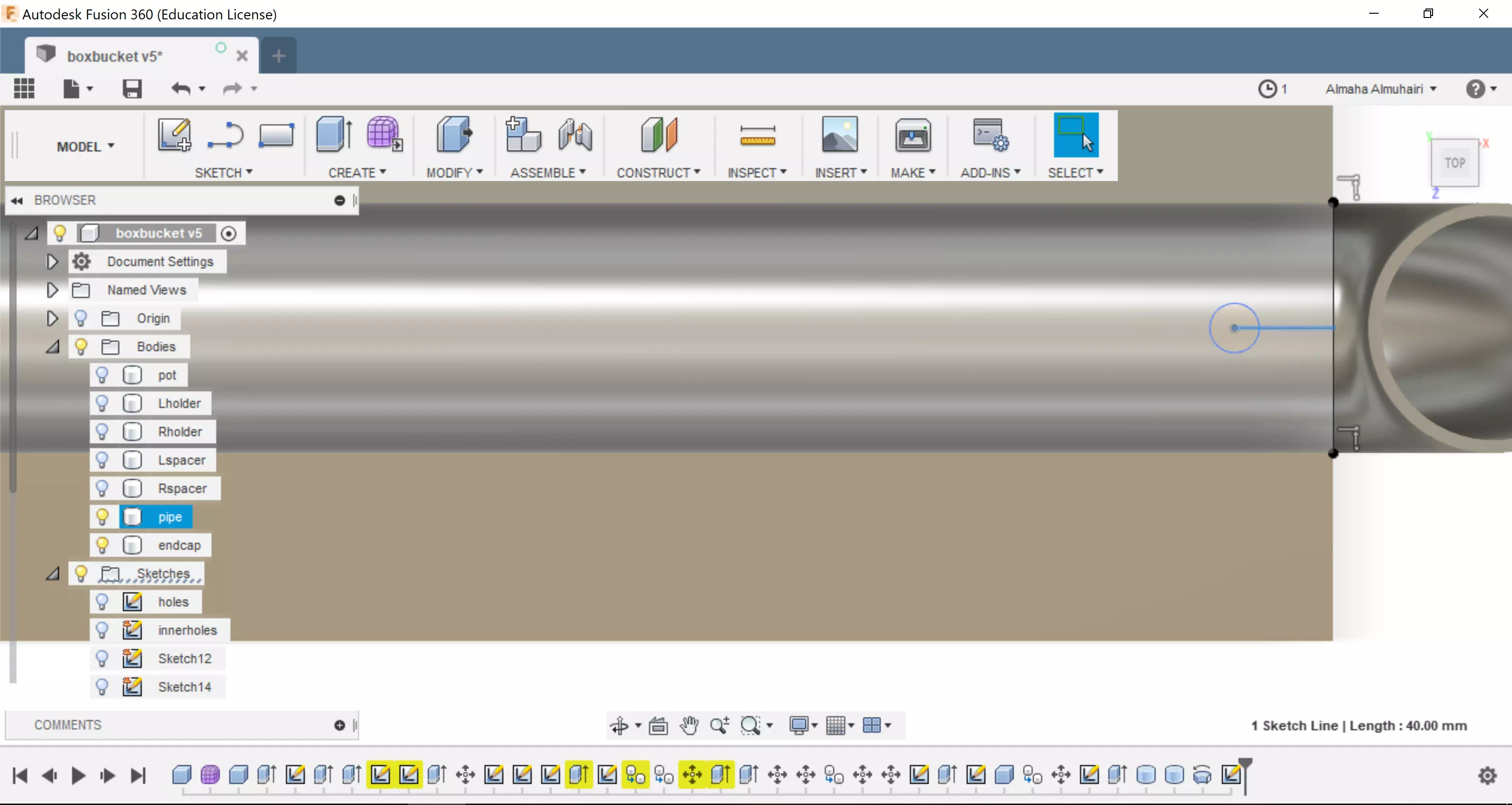
Using the sketch tool, create a line then create a center point circle at the end of the line.
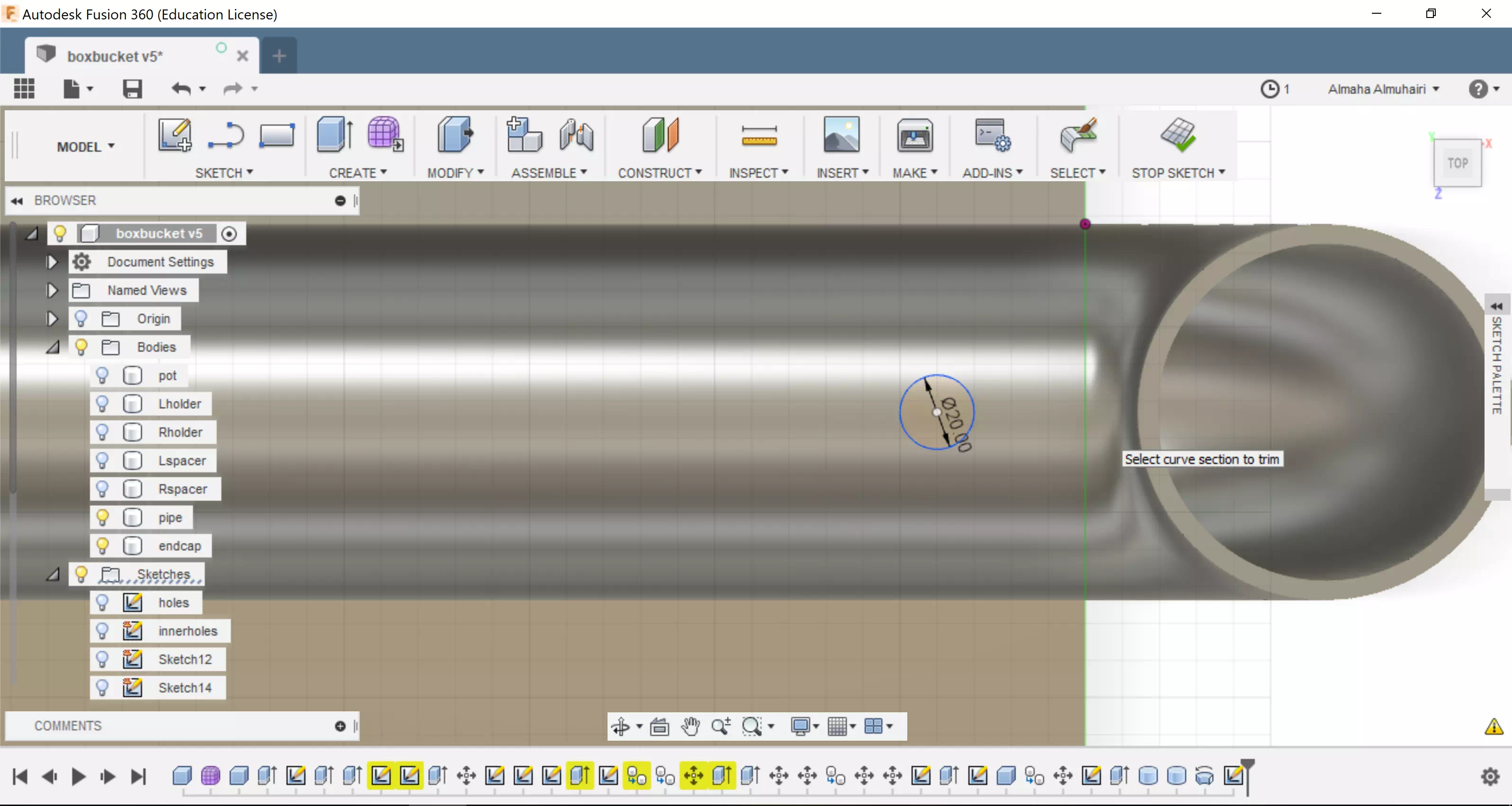
Using the trim tool remove the line and keep the circle sketch, it should look like this.
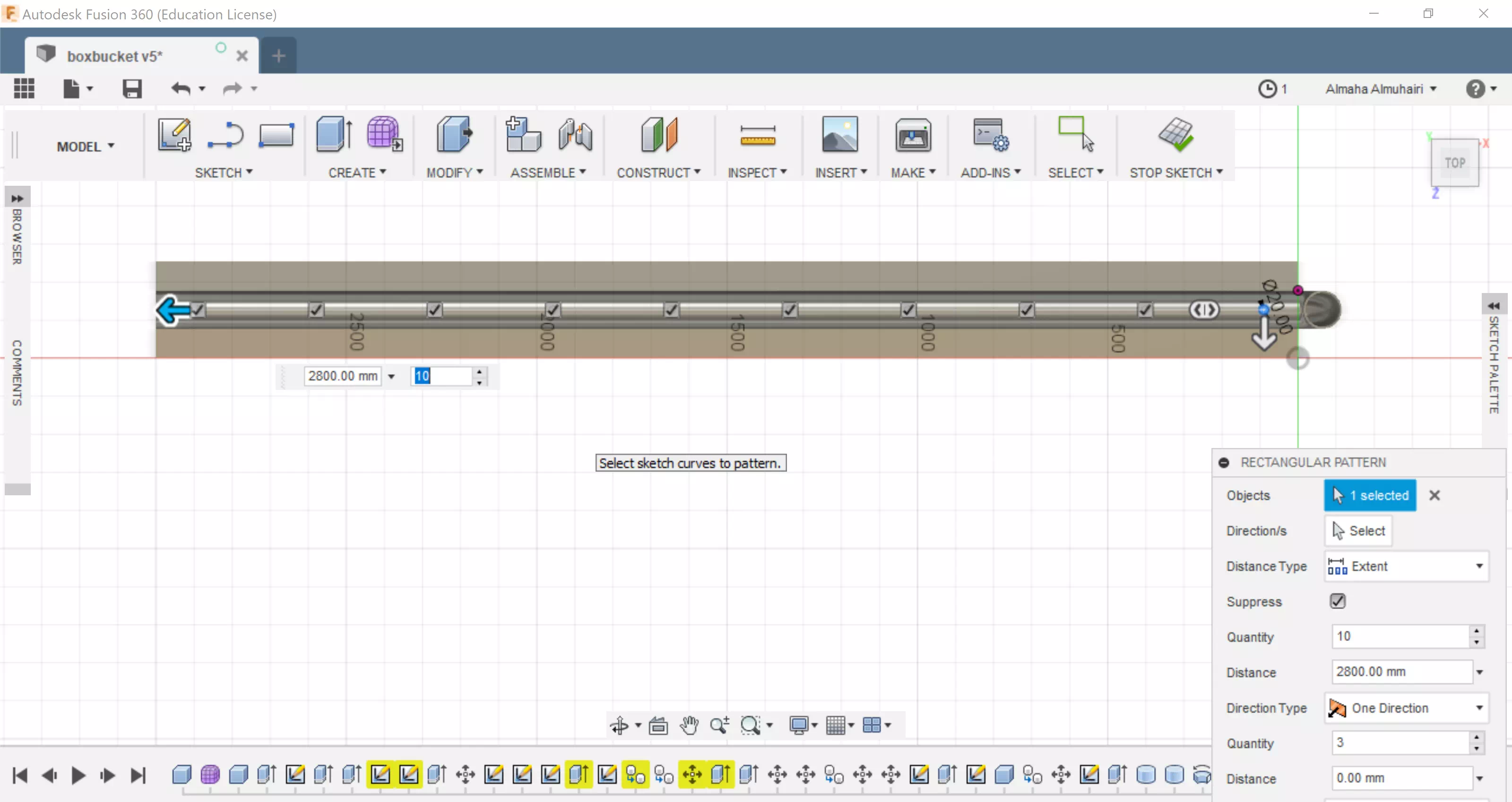
Using the rectangular pattern tool select the circle sketch and create an extent distance, add your desired amount of circles, we added 10 circles.
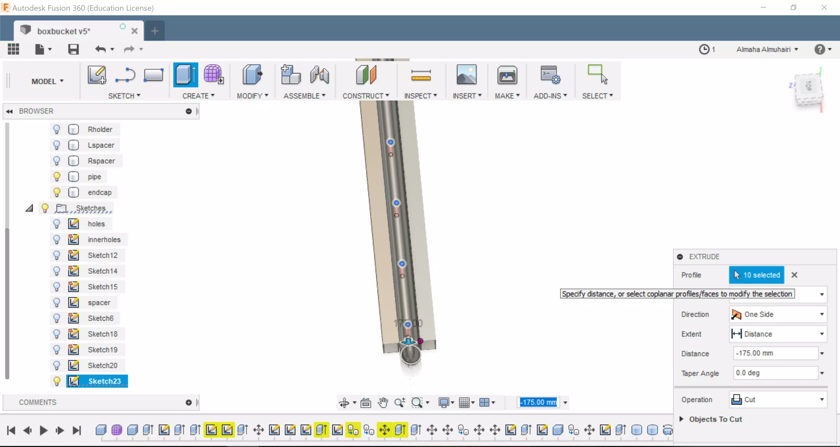
This is the last step for the base: Select all the circle sketches and extrude negatively to the Cut operation this will allow us to create holes in the pipe. Or you can just drag inwards/down.
The Movements (Putting all the parts together)
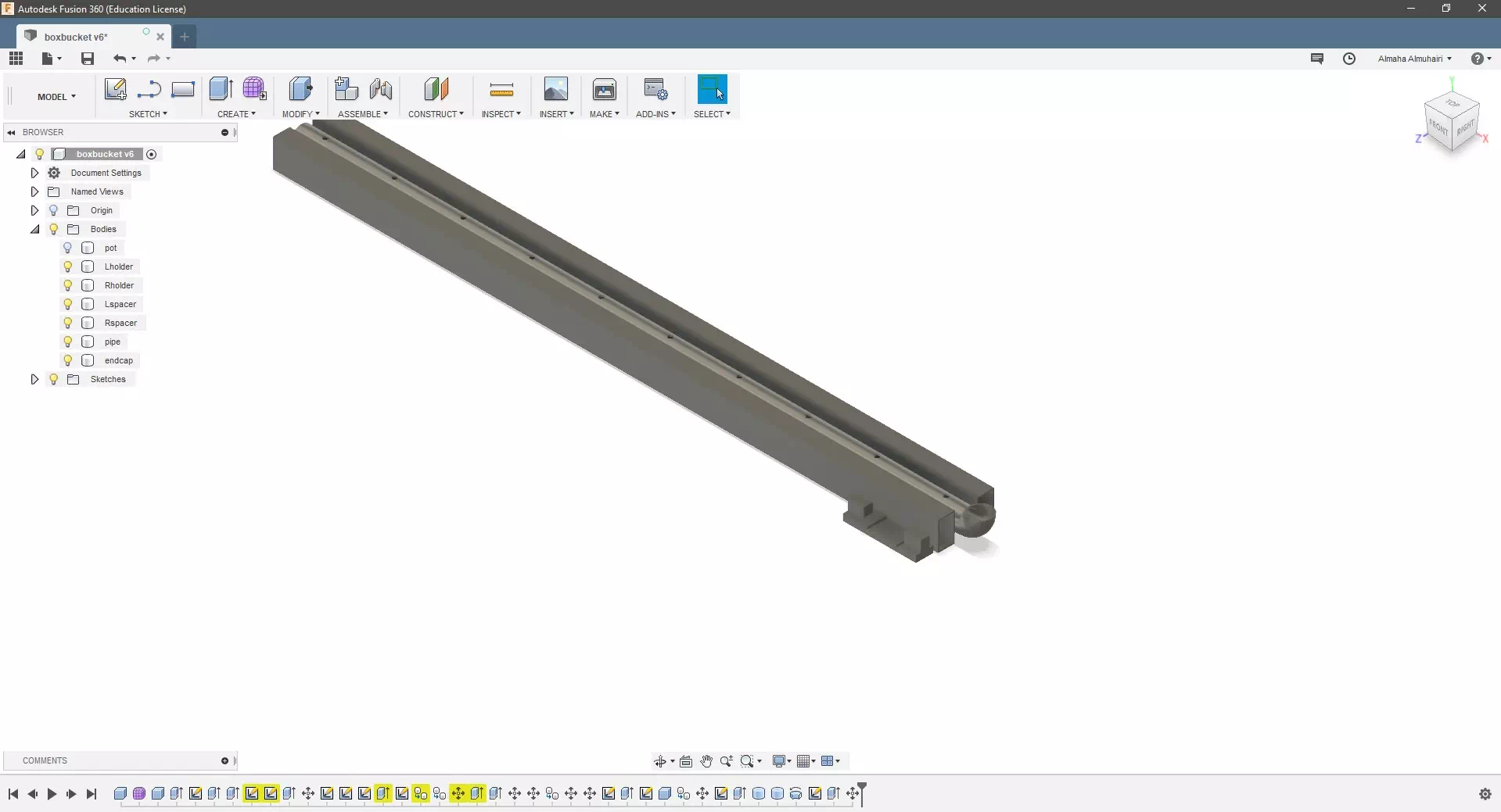
Start by turning on all the lightbulbs on the left hand side for the body's and turning off all the lightbulbs for the sketches.
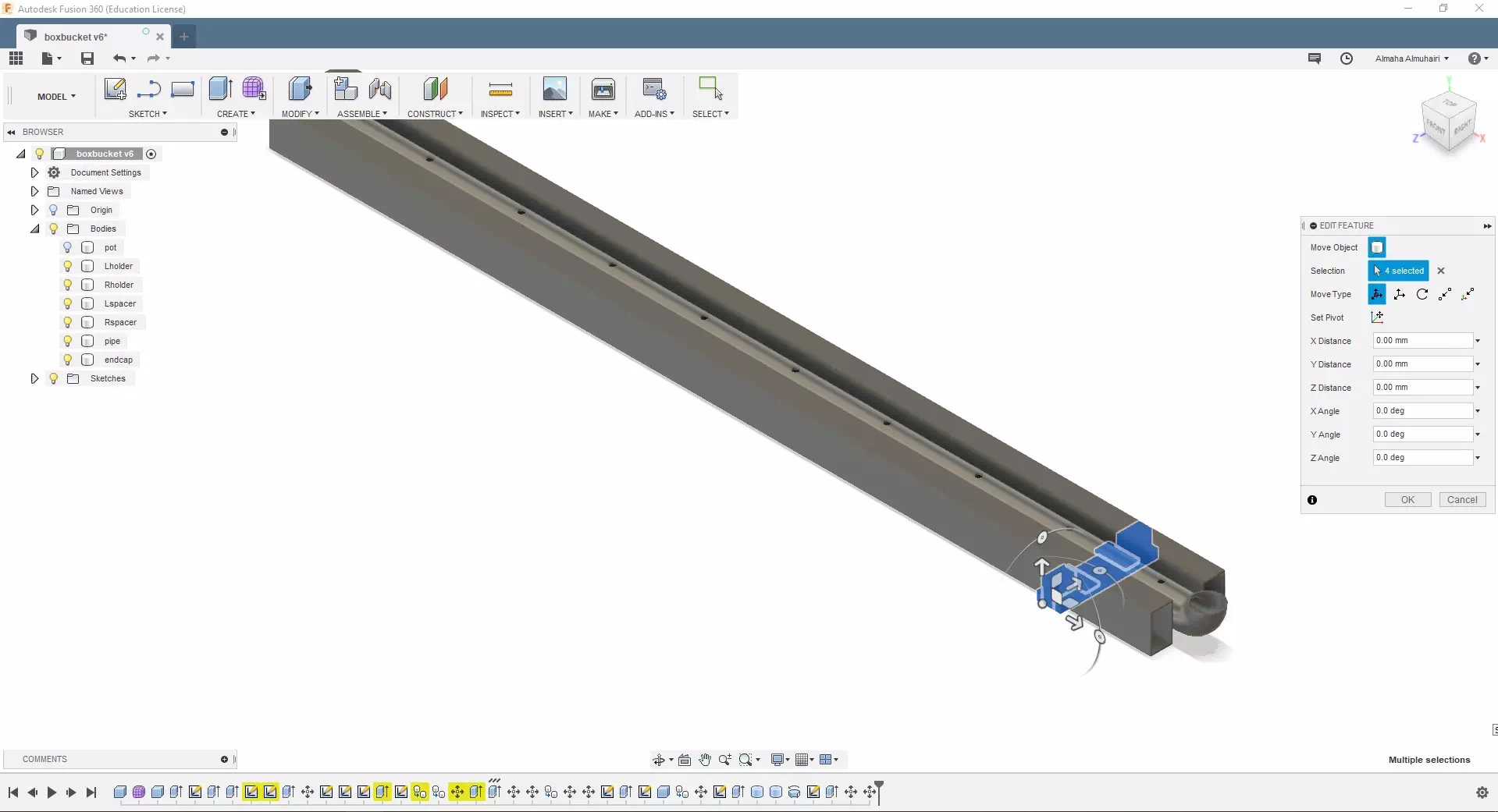
Right click and select the bracket body then, using the move tool, rotate the bracket.
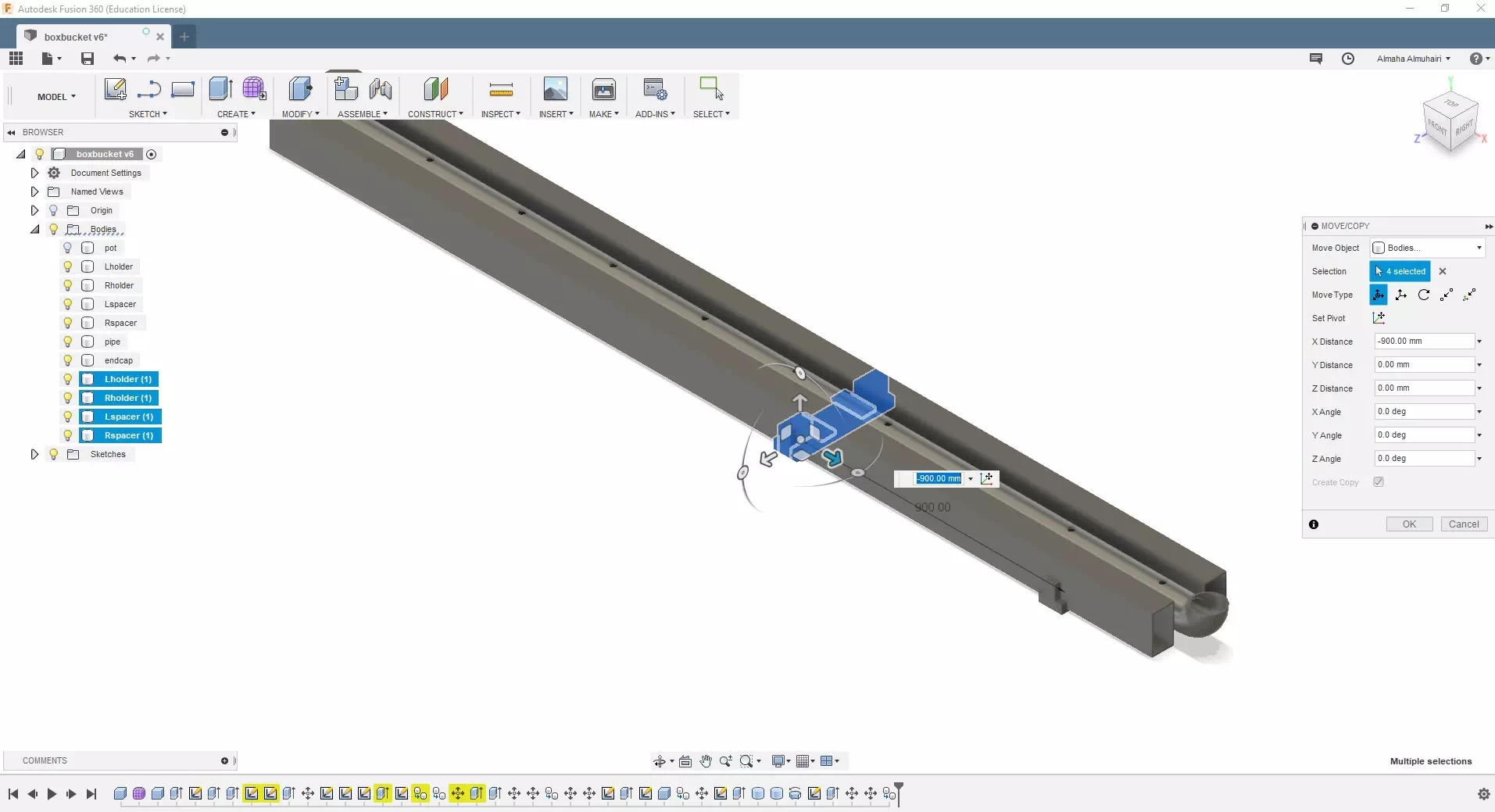
Move only the X axis of the bracket by (-820mm) and copy the brackets untill you have a total fo four brackets. Reapeat this step four times.
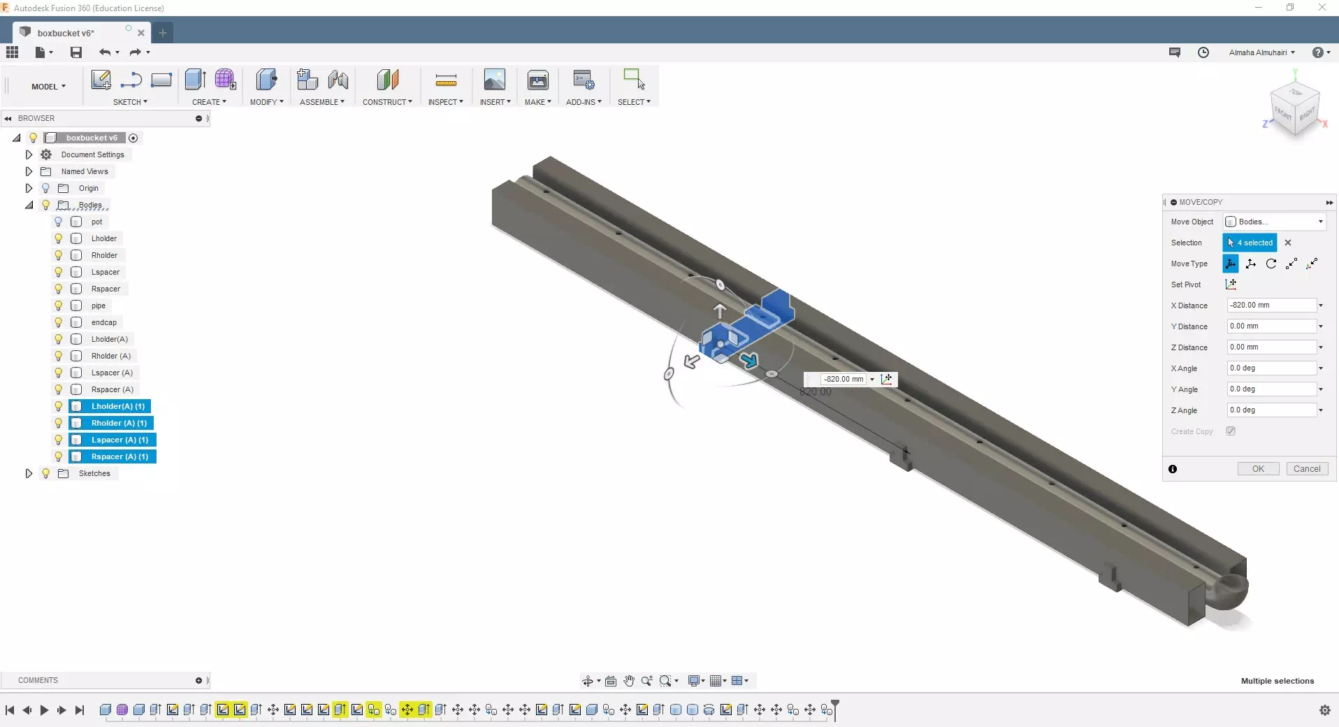
Reapeat the previous step four times.
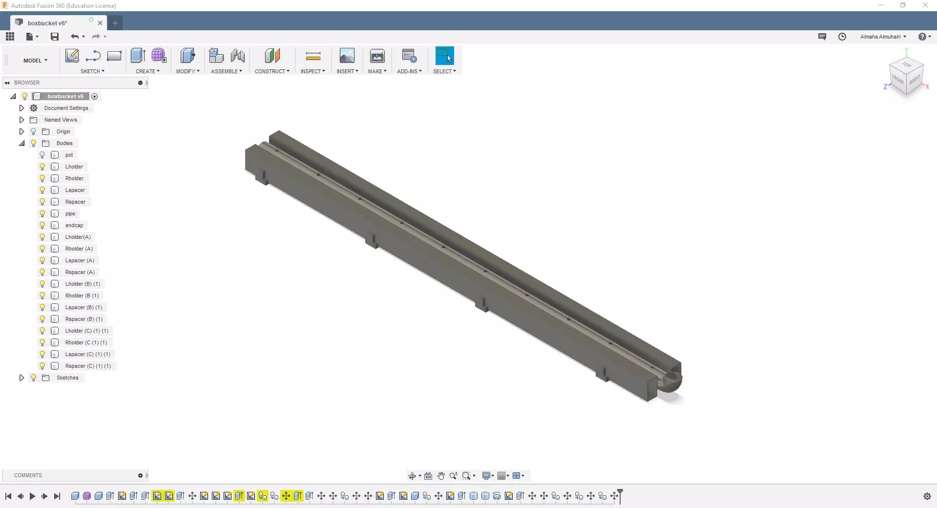
Your brackets placements should look like this.
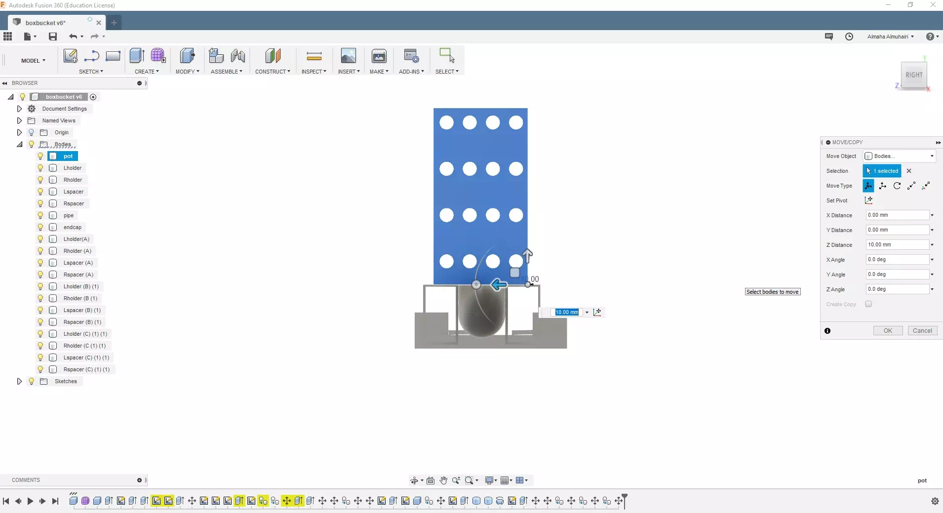
Turn the lightblub on for the pot and Move the pot upwards to place it on the base .
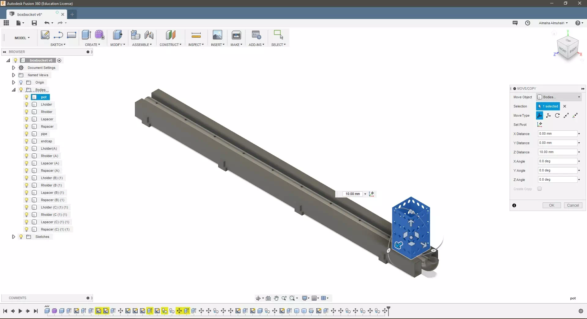
Your pot placement should look like this, it should be on top of each hole.
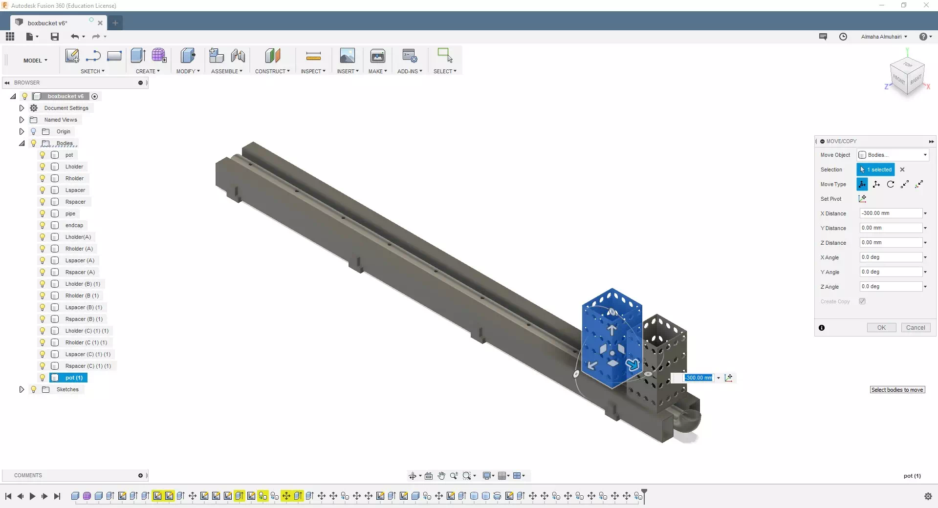
Move and create a copy of the pot on the X axis only by (-300mm). Repeat this step 9 times, you will have a total of ten pots to cover ten holes.
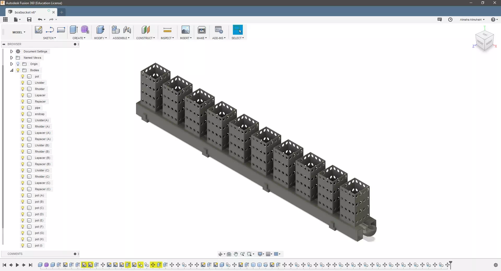
By the end your pots placements should look like this, it should be on top of each hole.
This is my 2D Model of my final project that I created using Corel Draw .

You may download my file here.
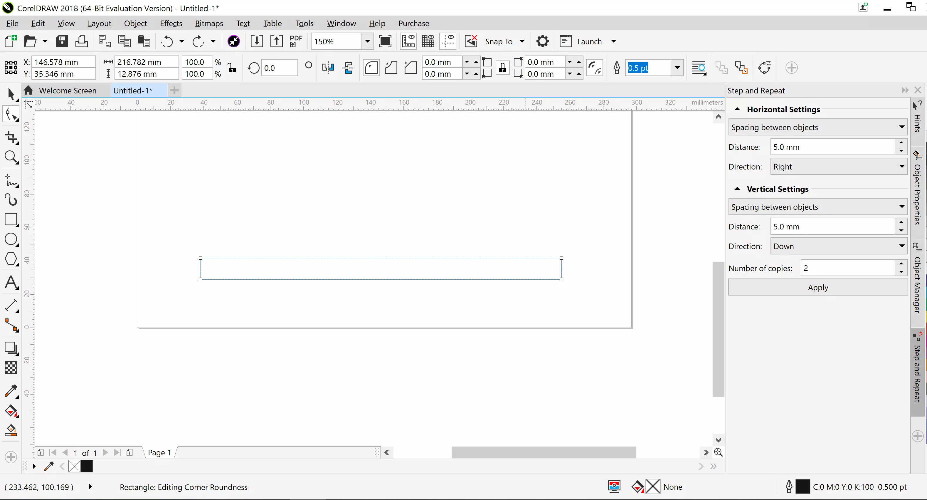
Start by drawing a rectangle.
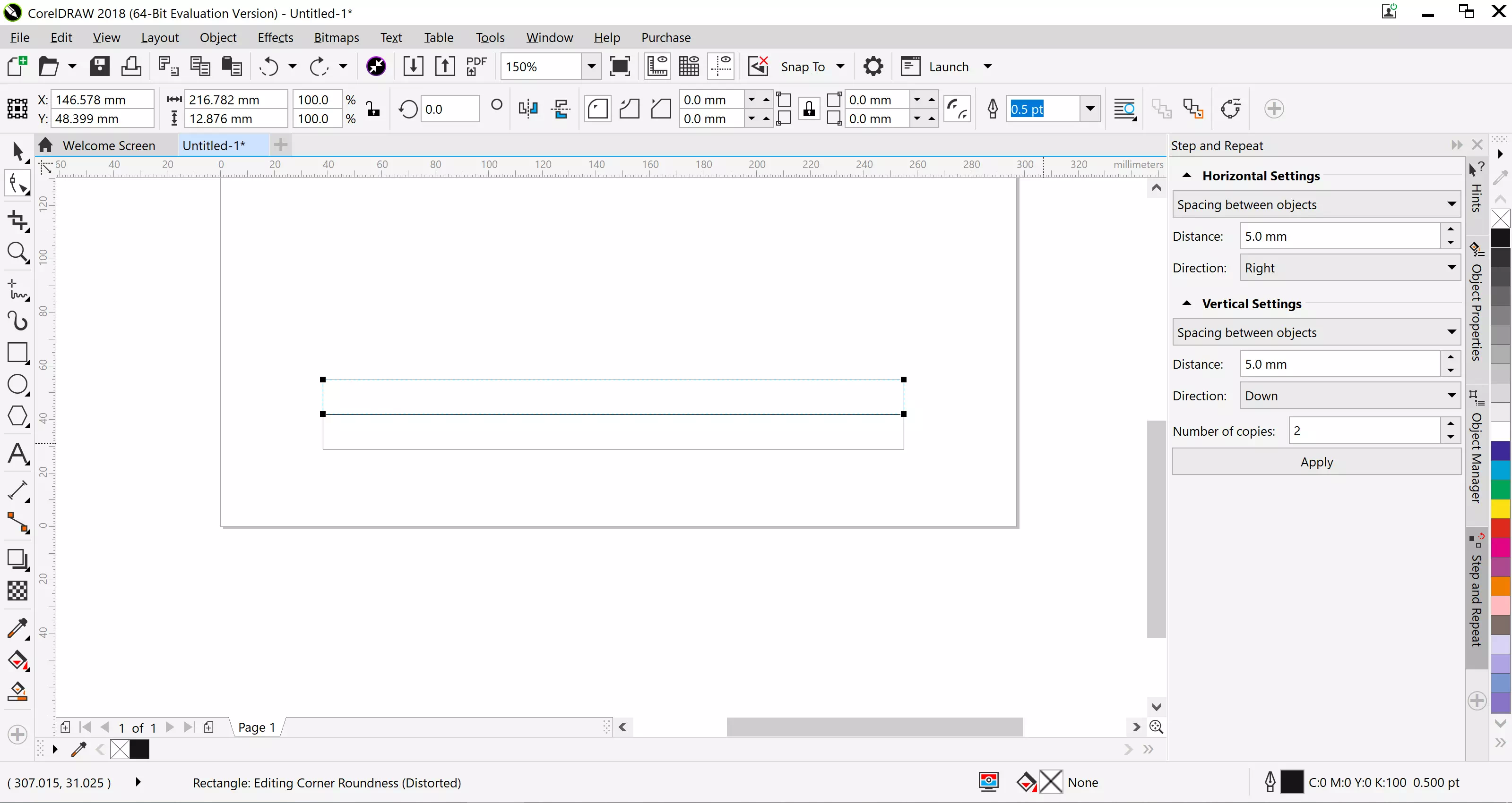
Copy and paste the rectangle, place the new rectangle directly above the other.
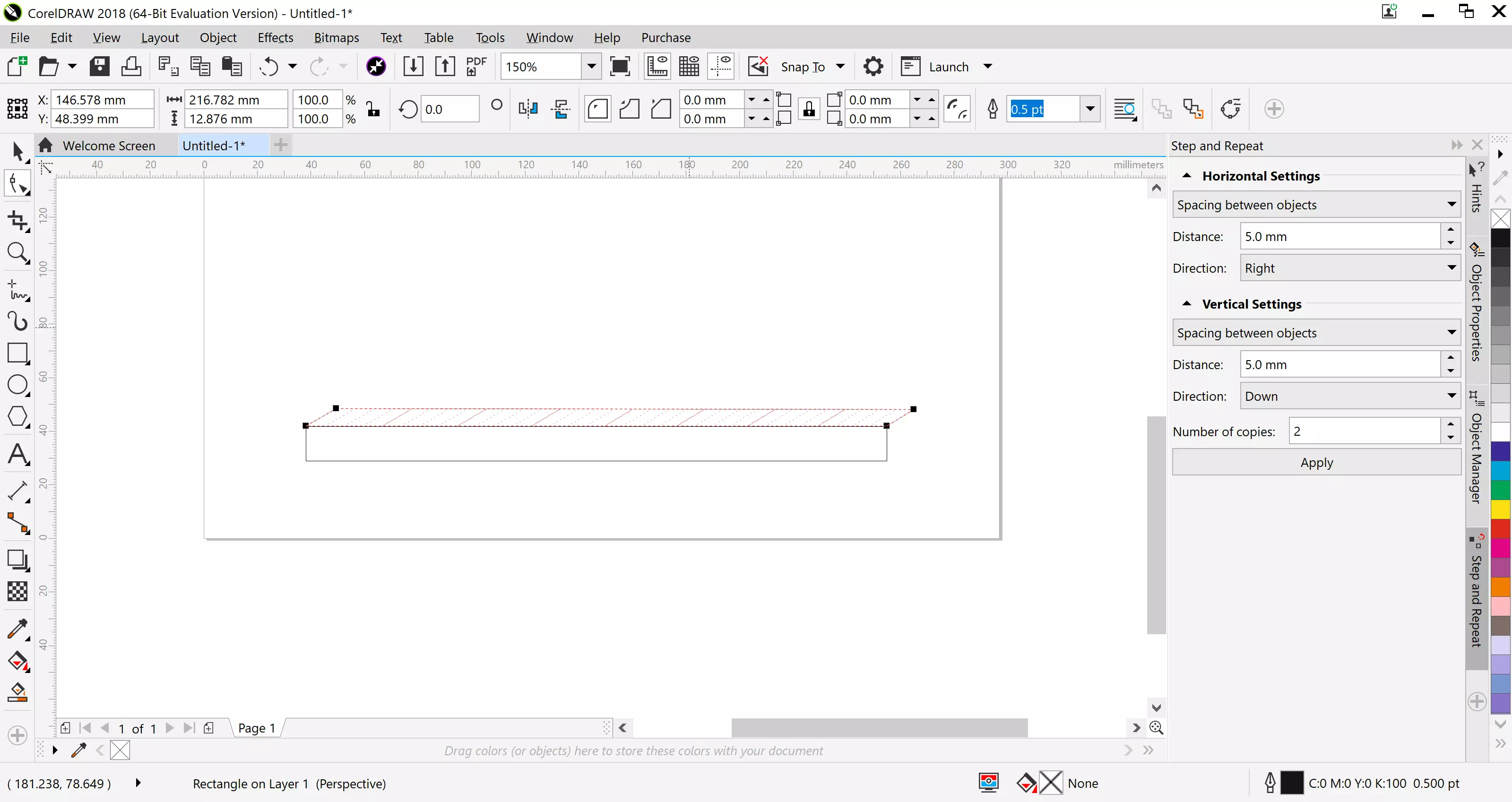
Select the copied rectangle and go to the Effects tab, using the add prespective effect, adjust the rectangle to make it look flat.
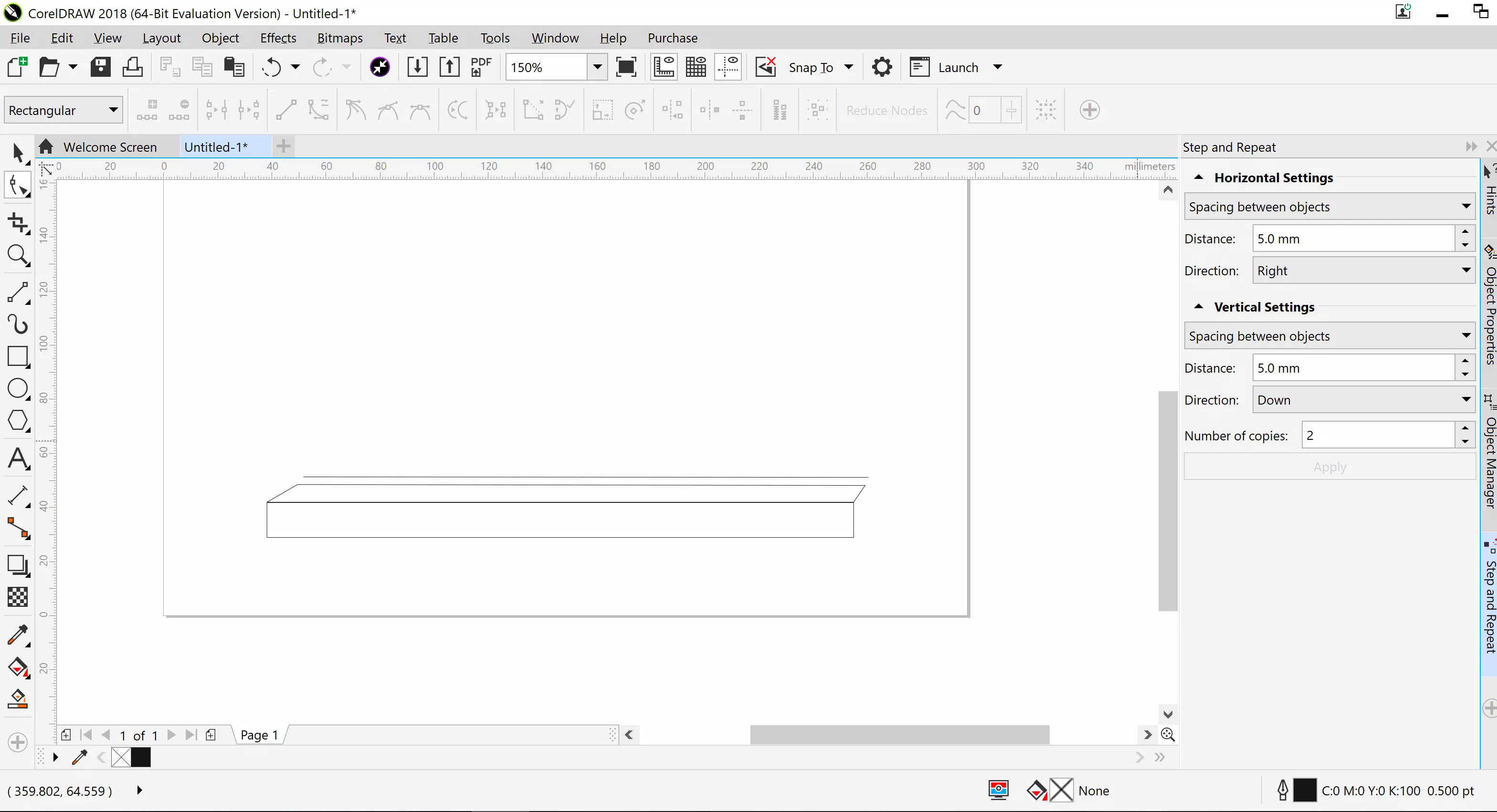
Create a line above the angle.
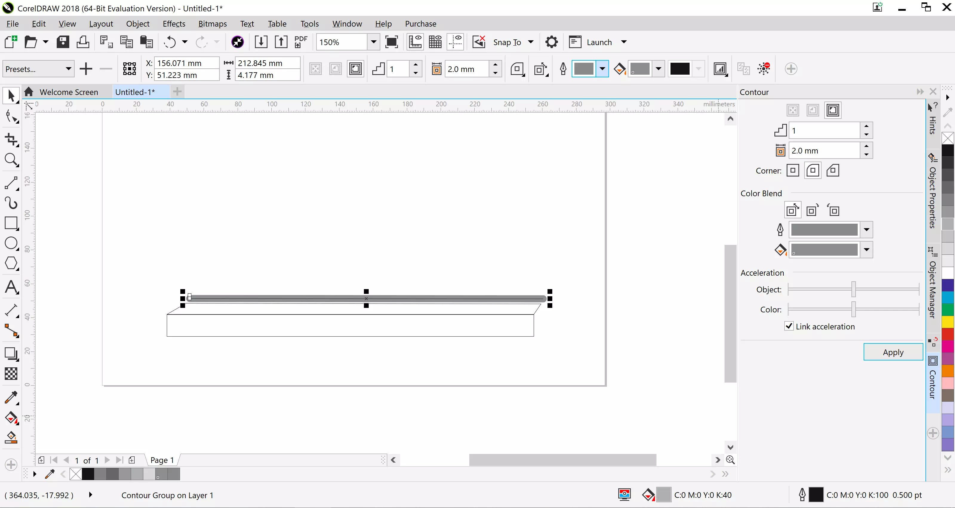
Click on the line and in the effects tab click the Contour effect, change the offset to adjust the thicknessto 4.5mm and the corners to round, and adjust the colors.
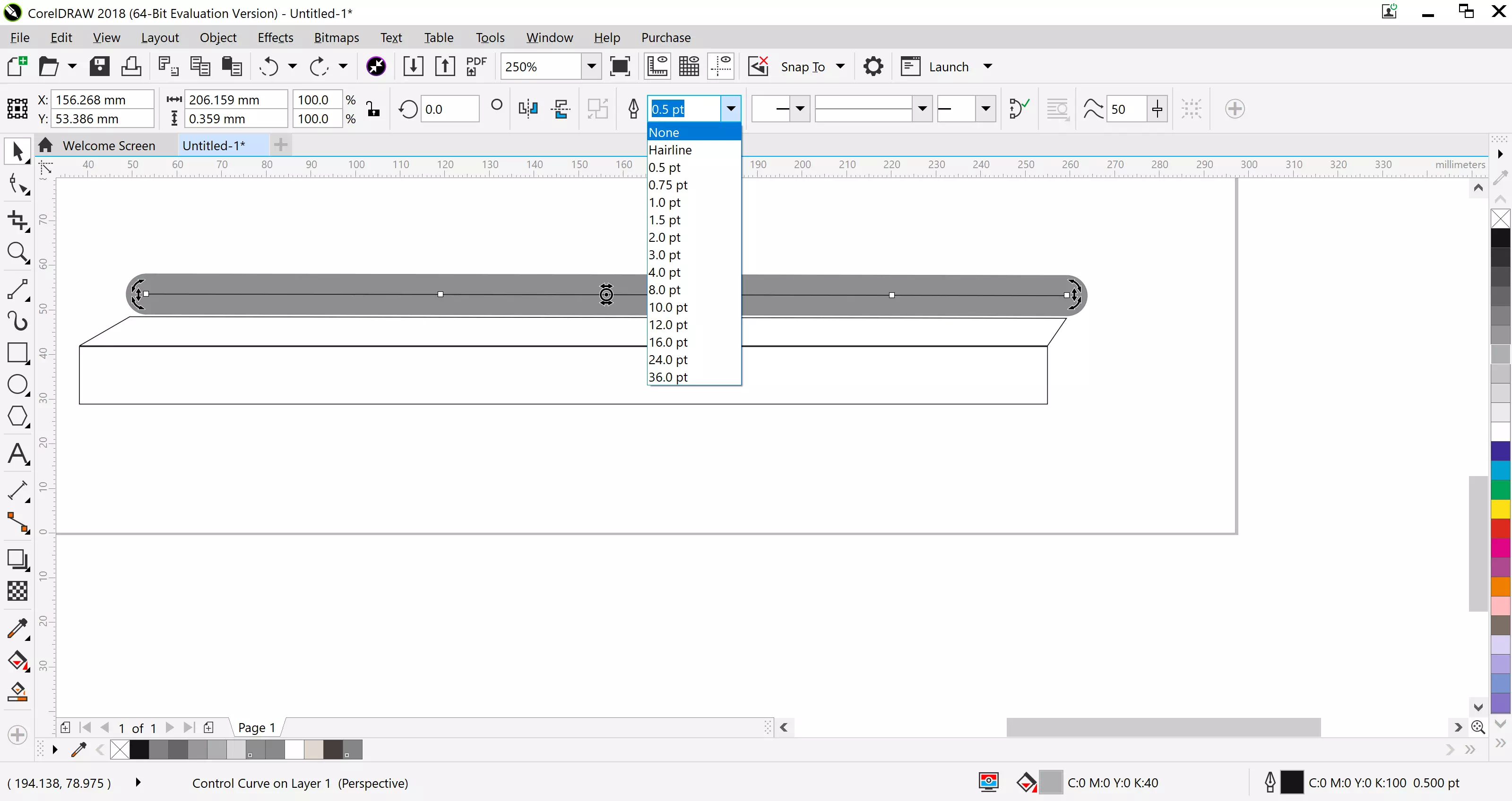
Click on the line and adjust it in the options to "none", this will remove the line.
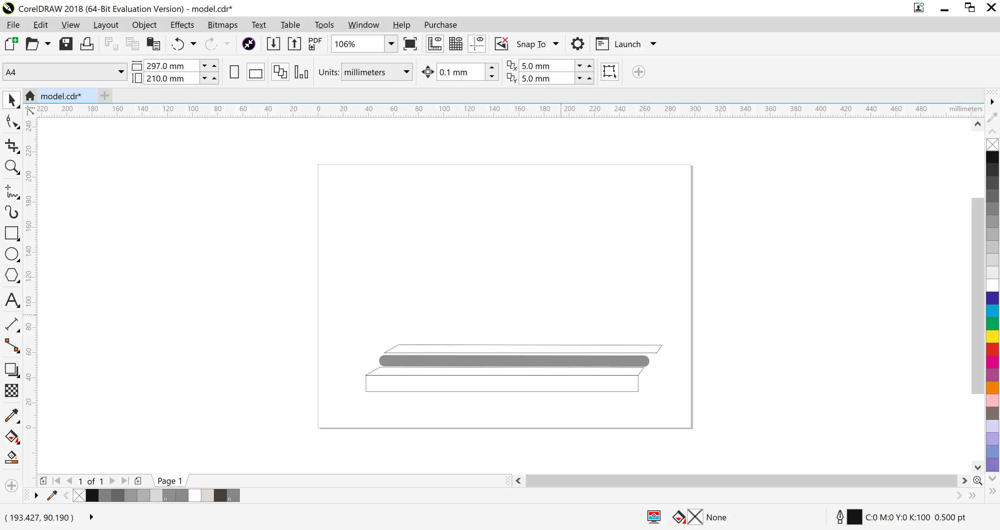
Copy and paste the rectangle that has prespective and move it on top of the grey line.
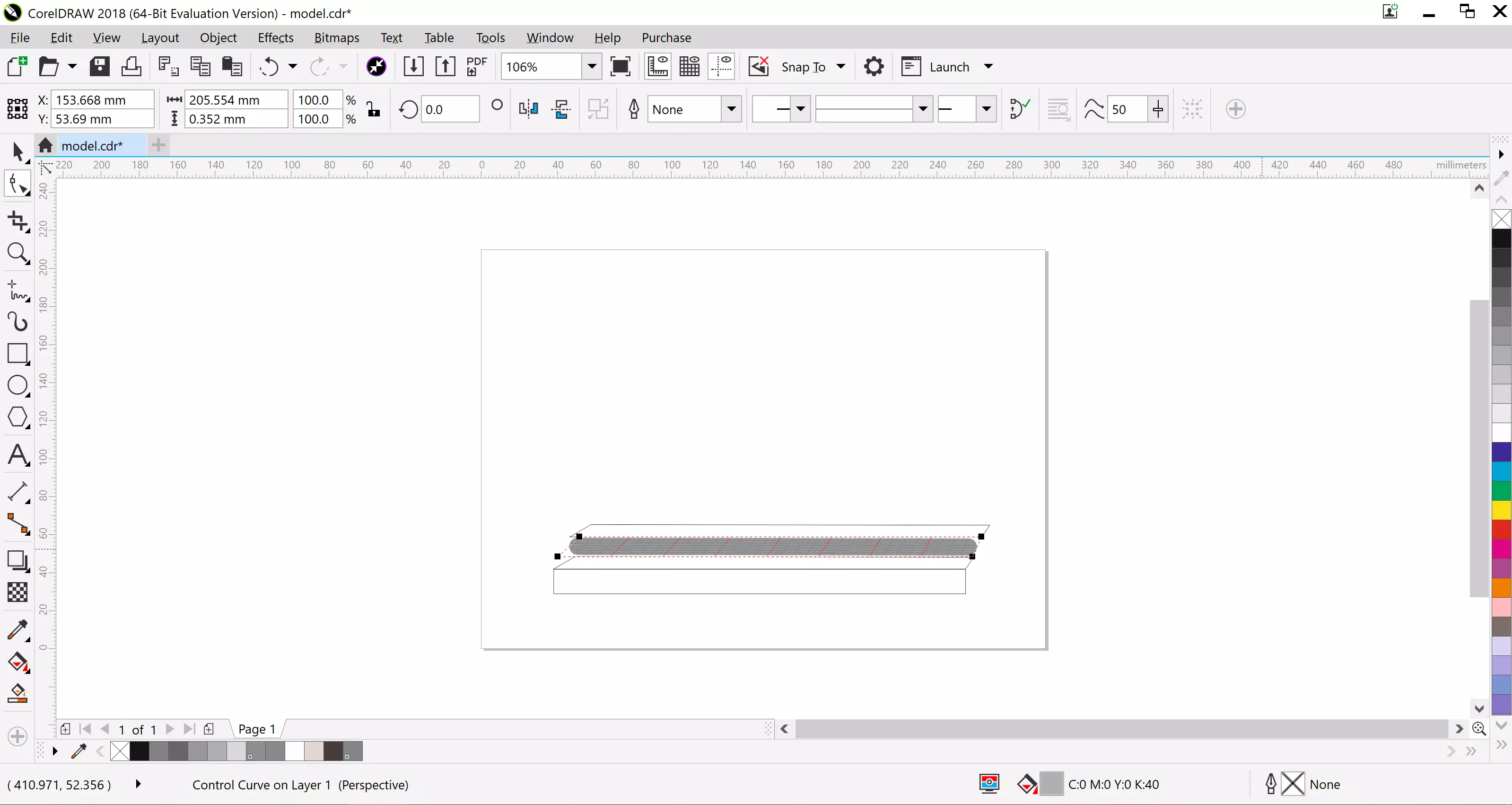
Using the effects tab click on the grey line and add prespective to make the grey line look flat.
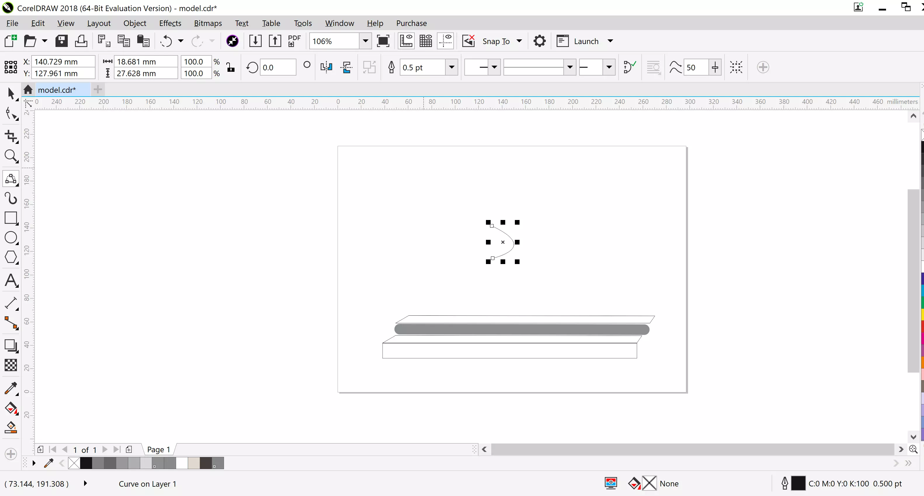
Create a three point curve, you can find it from the tool bar.
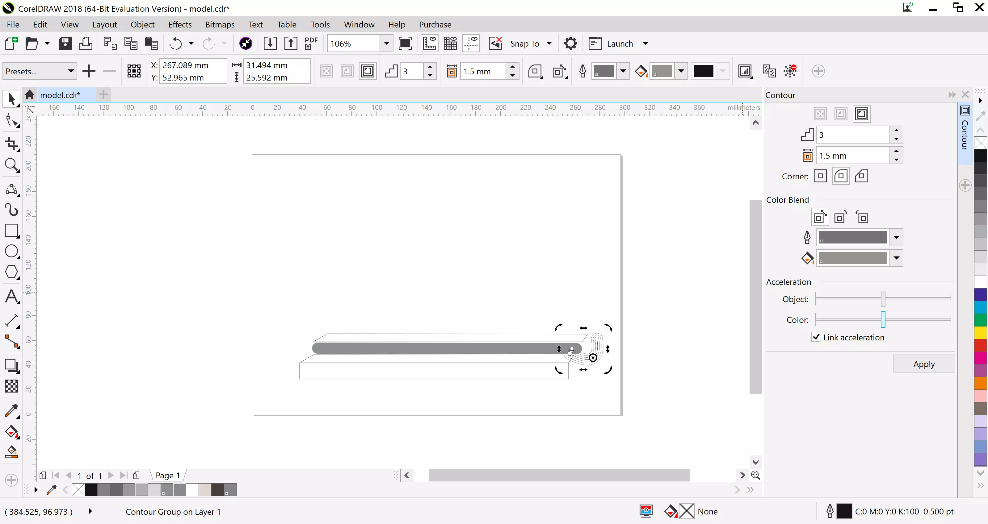
Move the three point curve to the right end of the grey line and adjust the size, then use the contour tool from the effects tab, adjust the offset to 1.45mm.
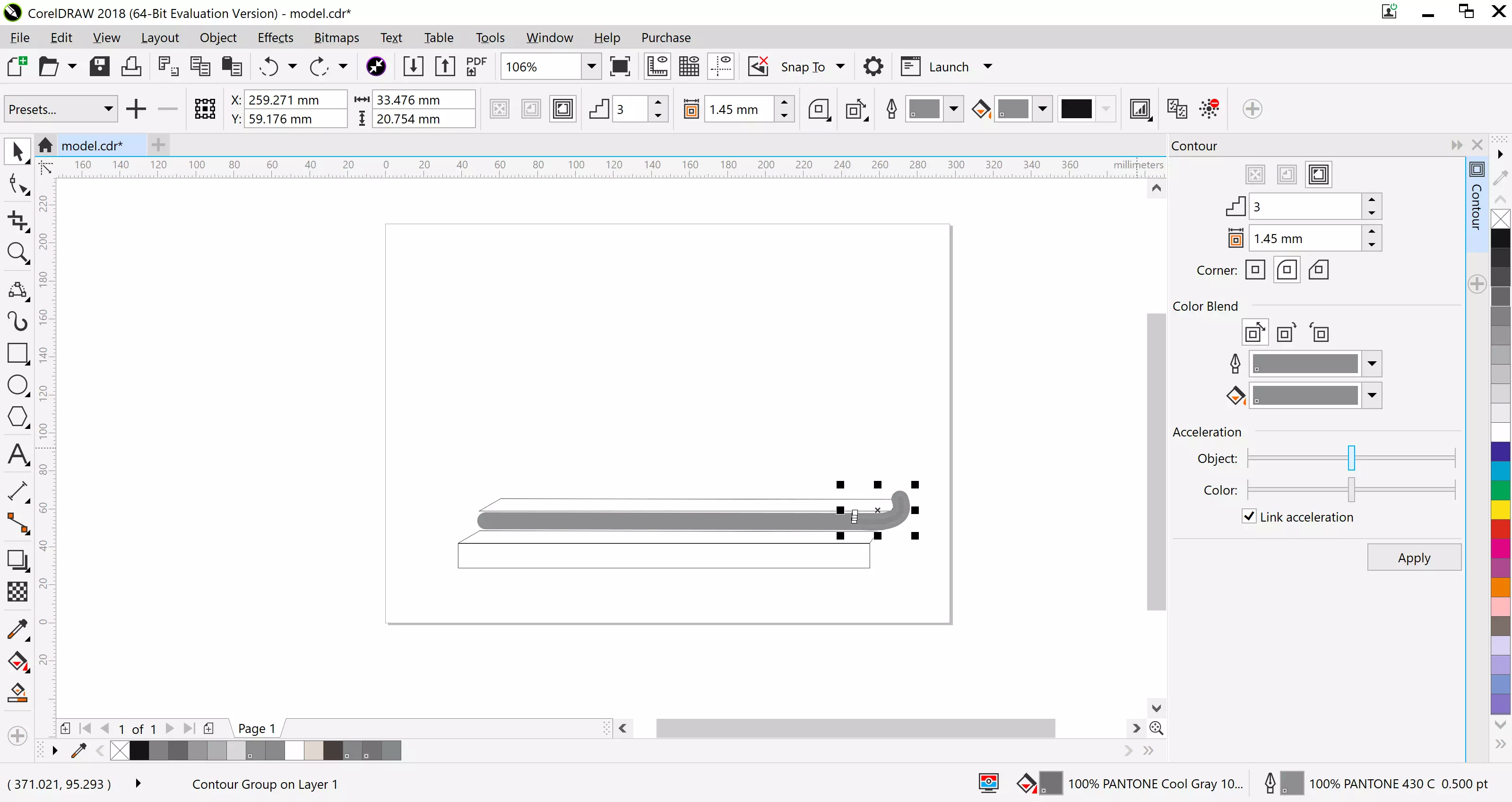
Still in the contour tool, adjust the color using the color options to match the grey line.
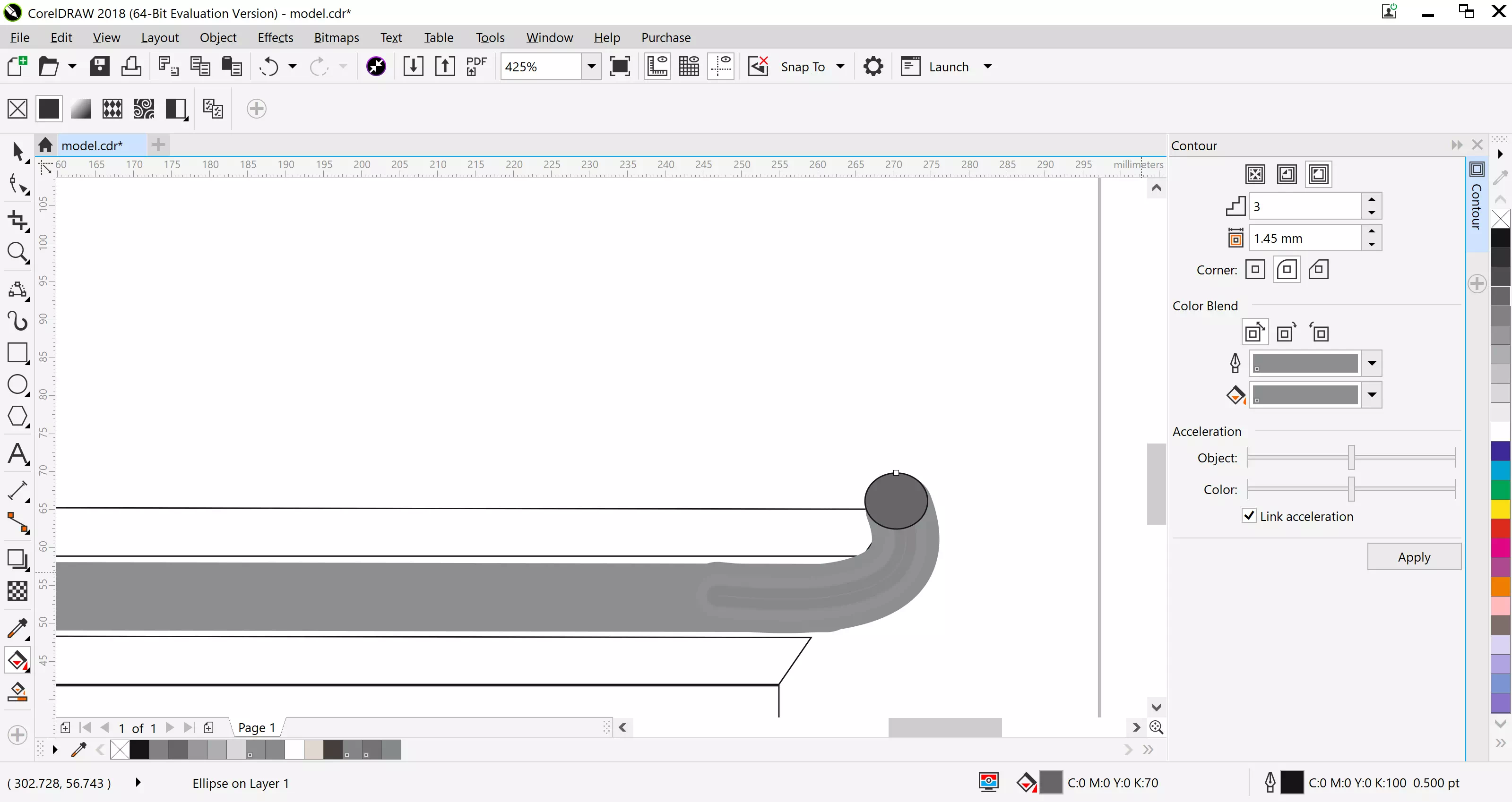
At the end of the curve, create a circle and fill it with a darker grey color.
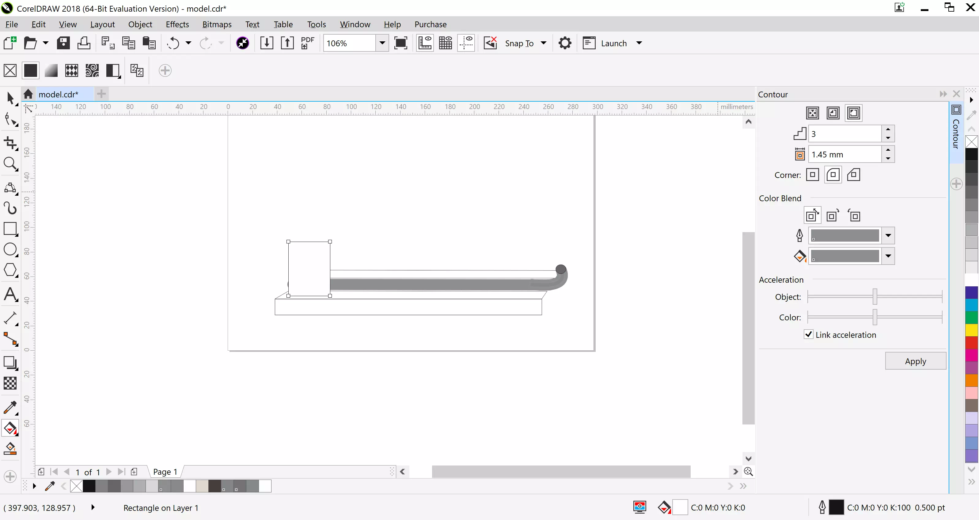
Start by drawing a rectangle, fill it with white .
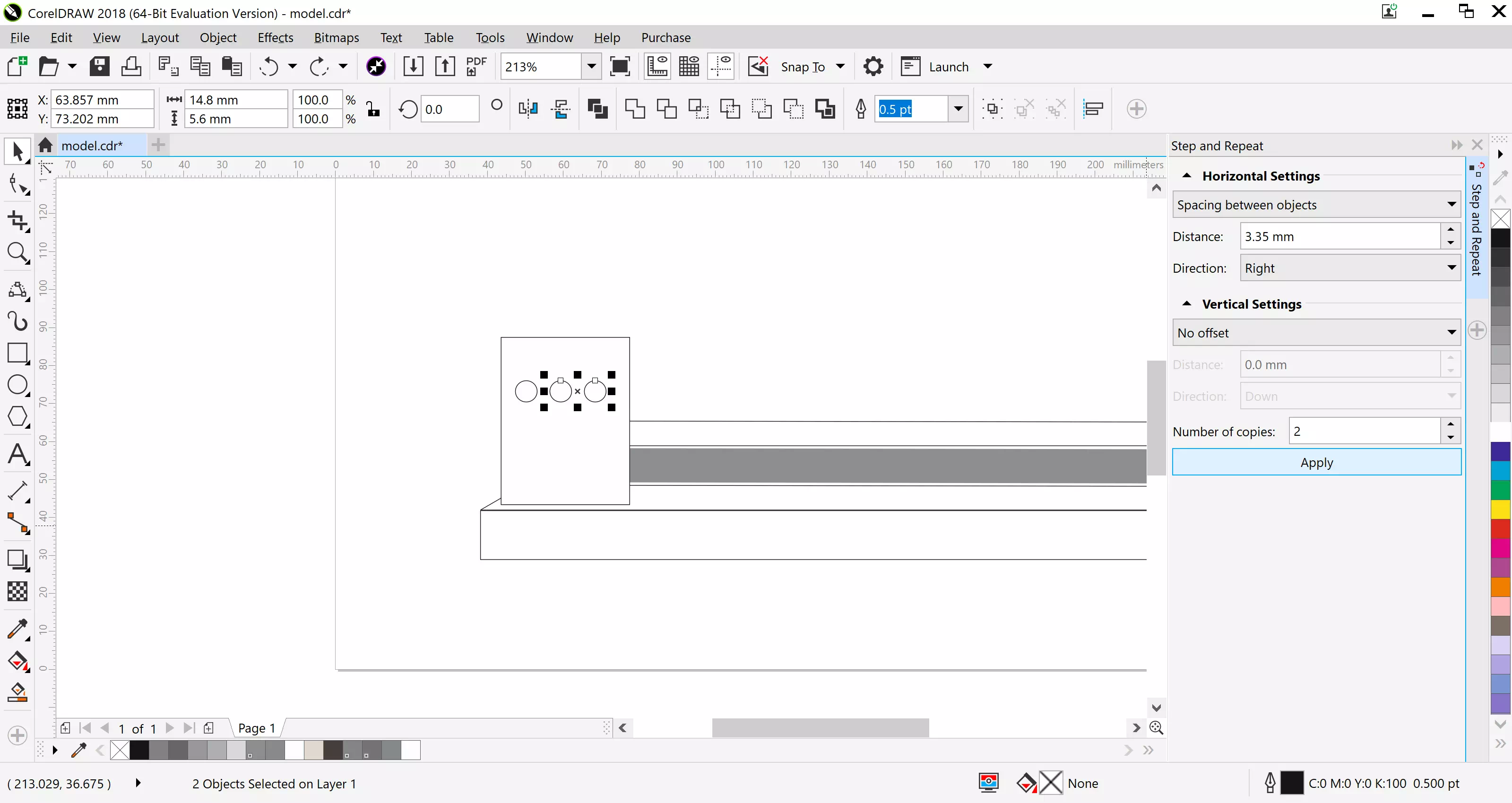
On the rectangle, create a circle on the face and in the Edit tab use the step and repeat tool to create more circles as a pattern to follow horizontally.
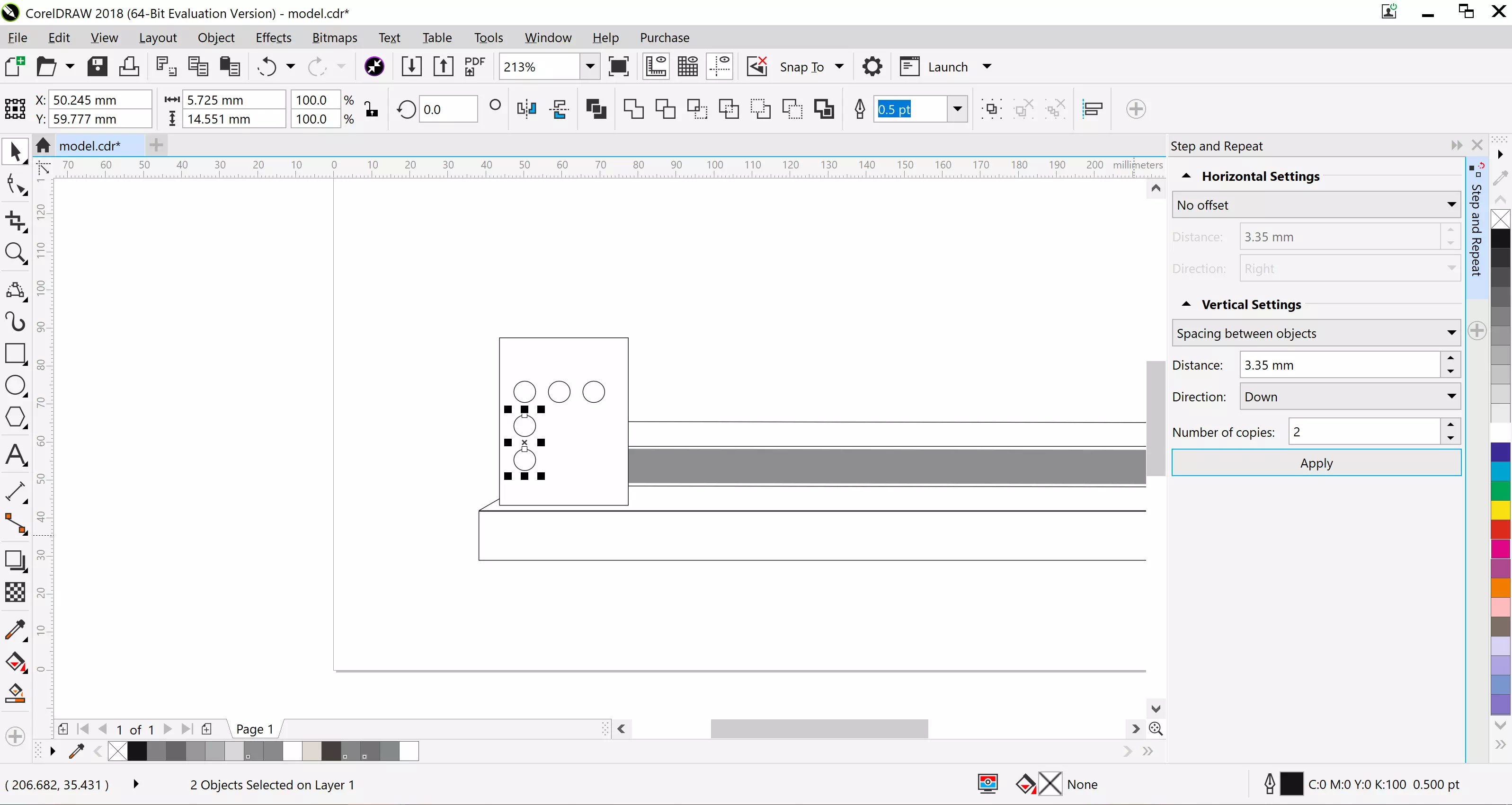
On the rectangle, create a circle on the face and in the Edit tab use the step and repeat tool to create more circles as a pattern to follow vertically.
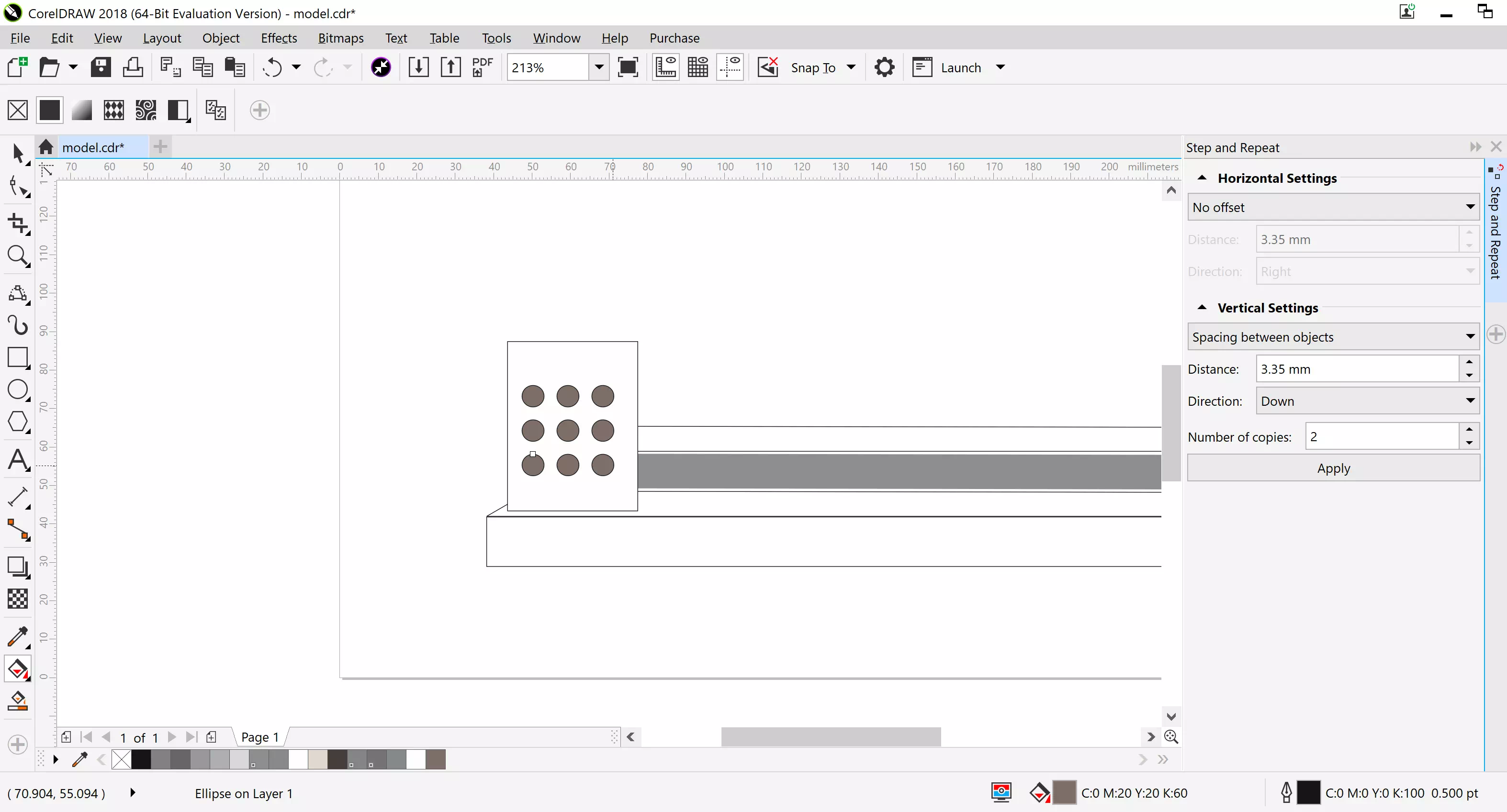
Fill the circles with the color brown, using the fill bucket.
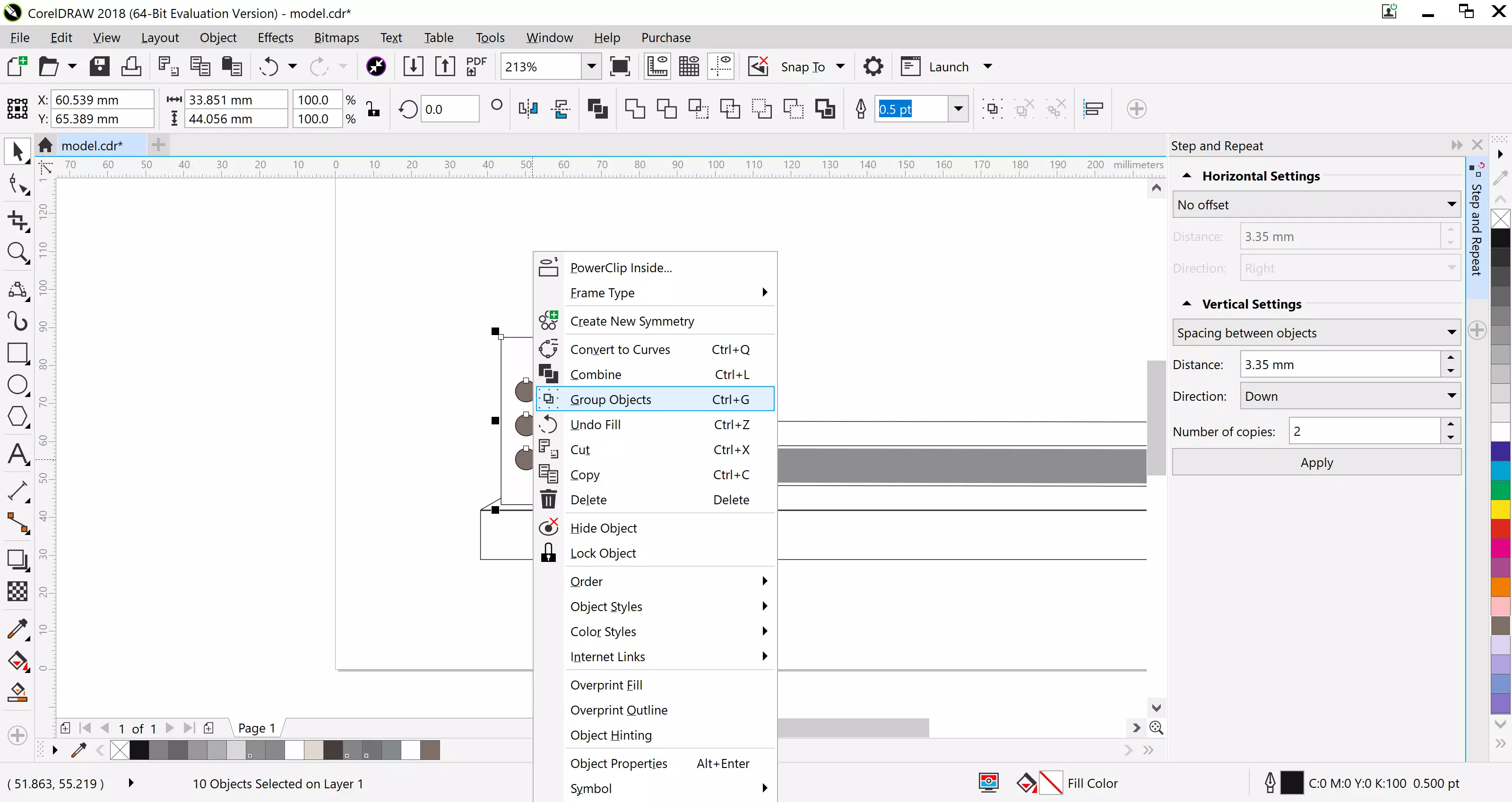
Group the rectangle with the circles by selecting them the right clicking the option.
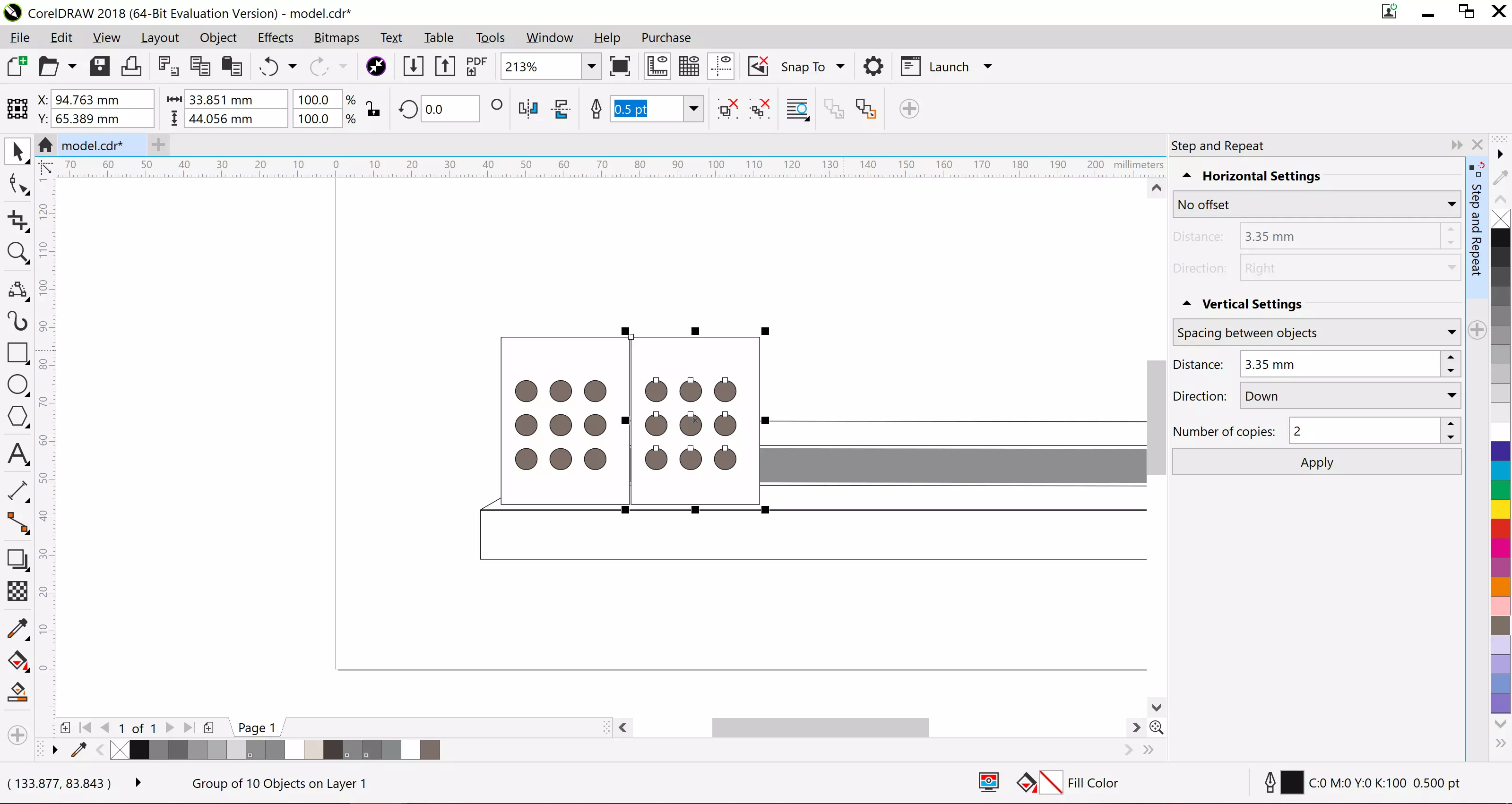
In the Edit tab use the step and repeat tool to create a pot face to copy the exact group.Repeat it only once and keep a close distance.
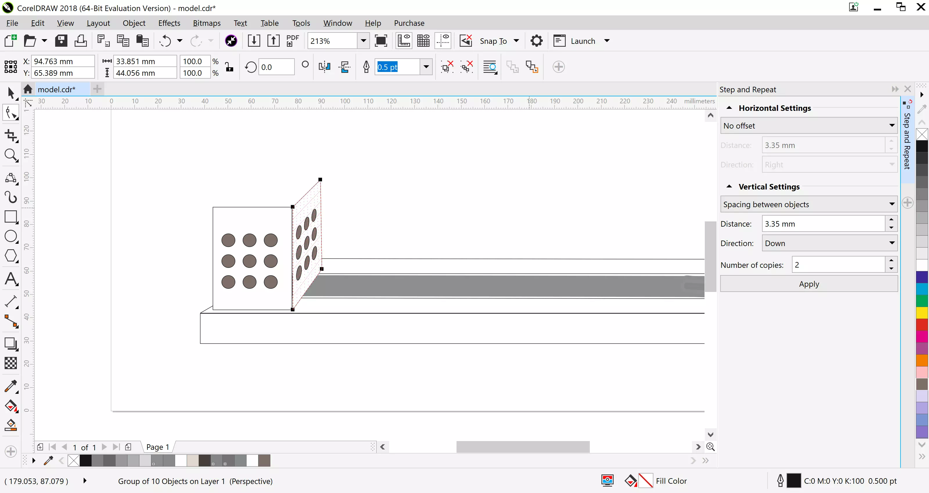
Click on the copied pot face and using the effects tab add prespective by adjusting to create an angle inwards.
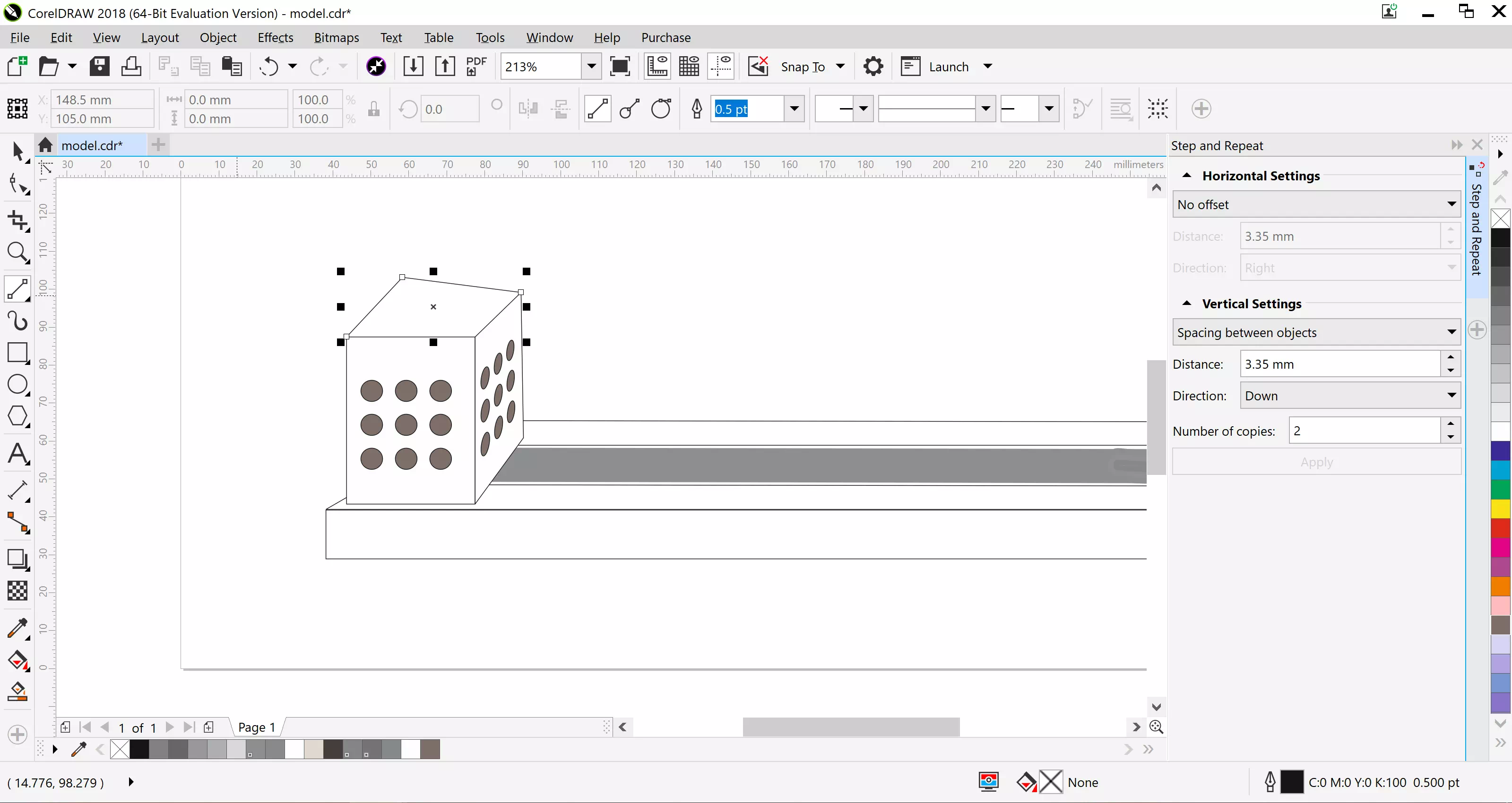
Draw a rectangle on top of both corners
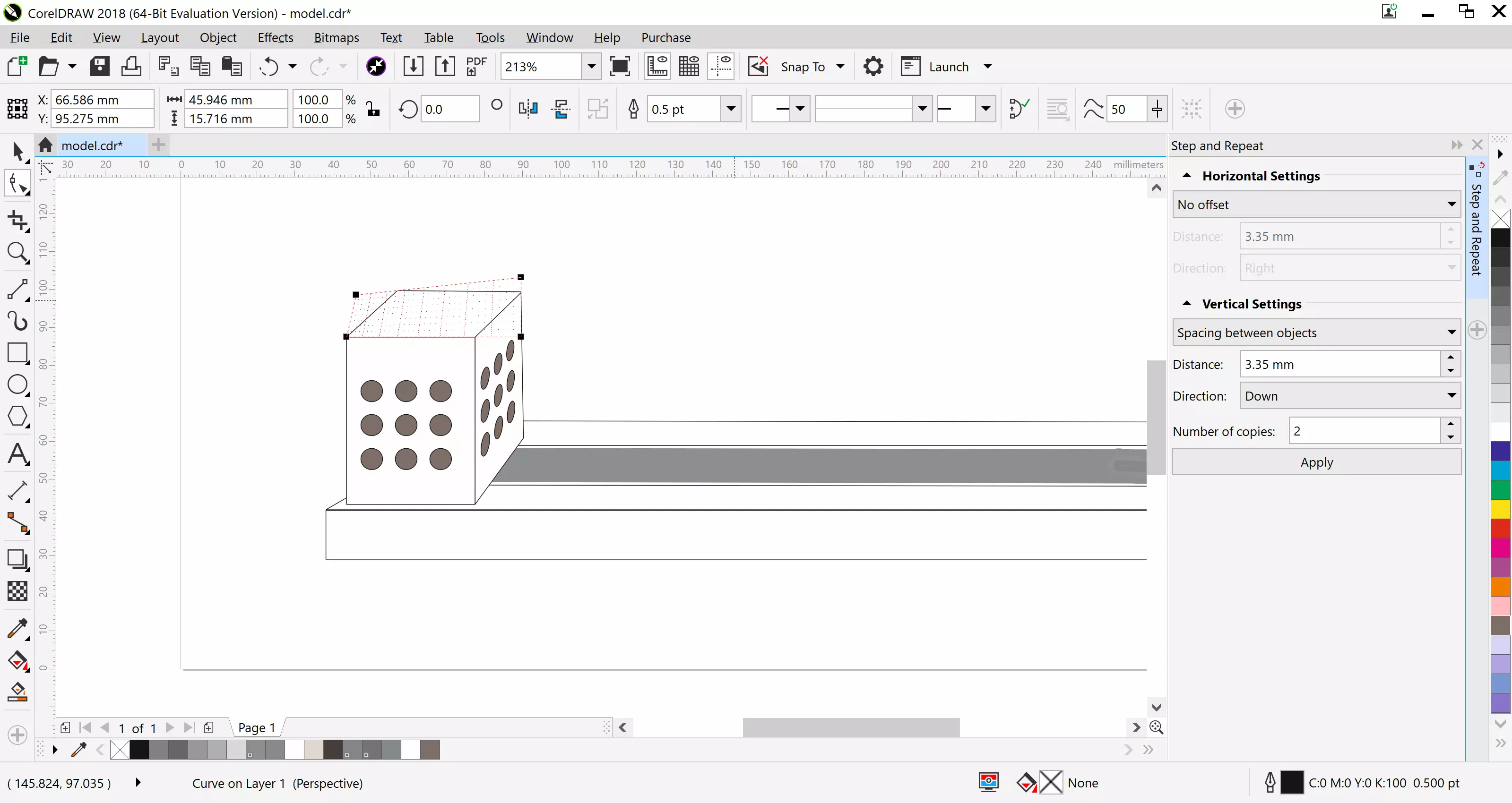
Click on the top rectangle and using the effects tab add prespective to make it look flat.
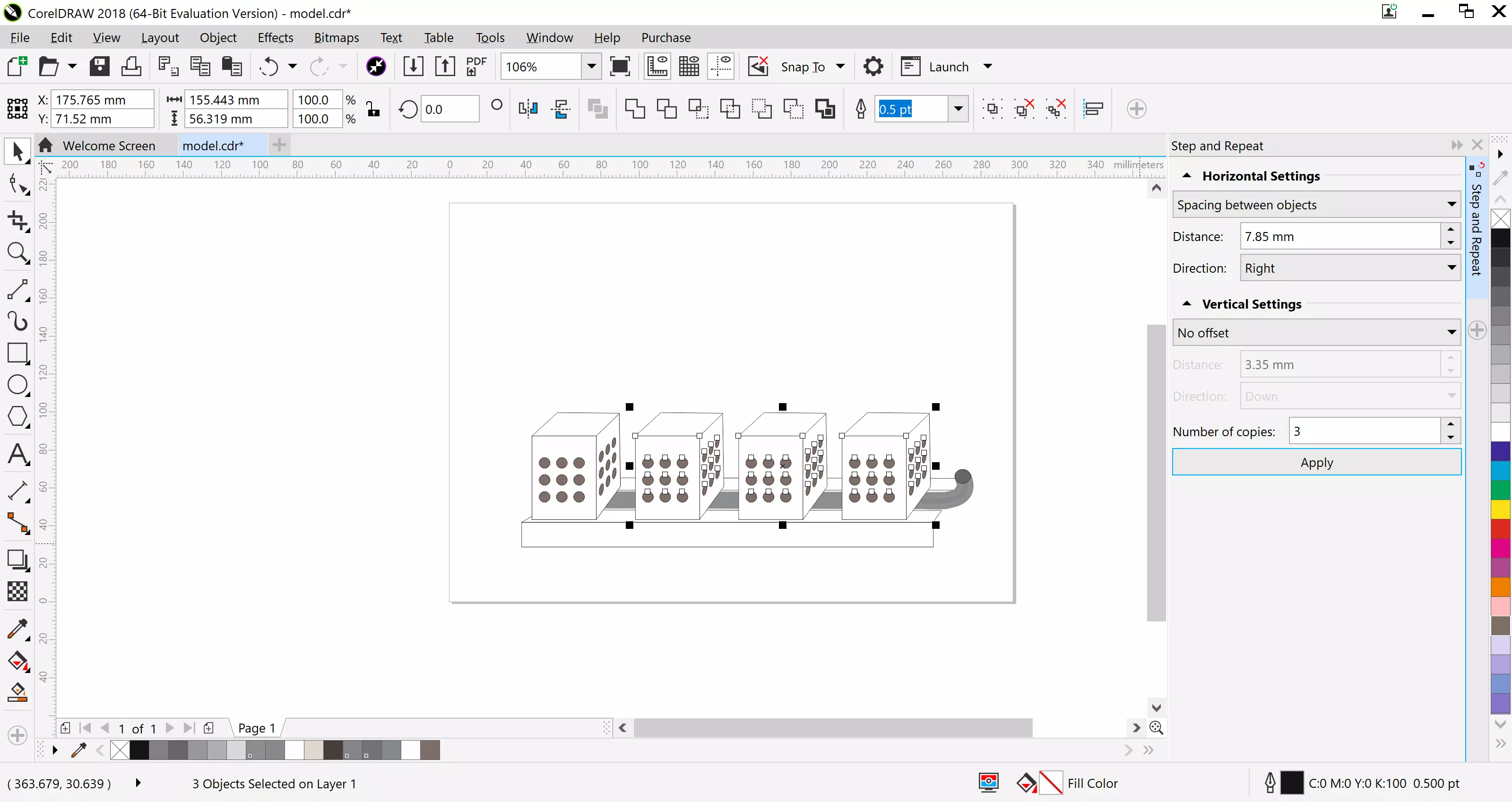
Group all the faces in the pot, then In the Edit tab use the step and repeat tool three times with a distance of 7.85mm towards the right.
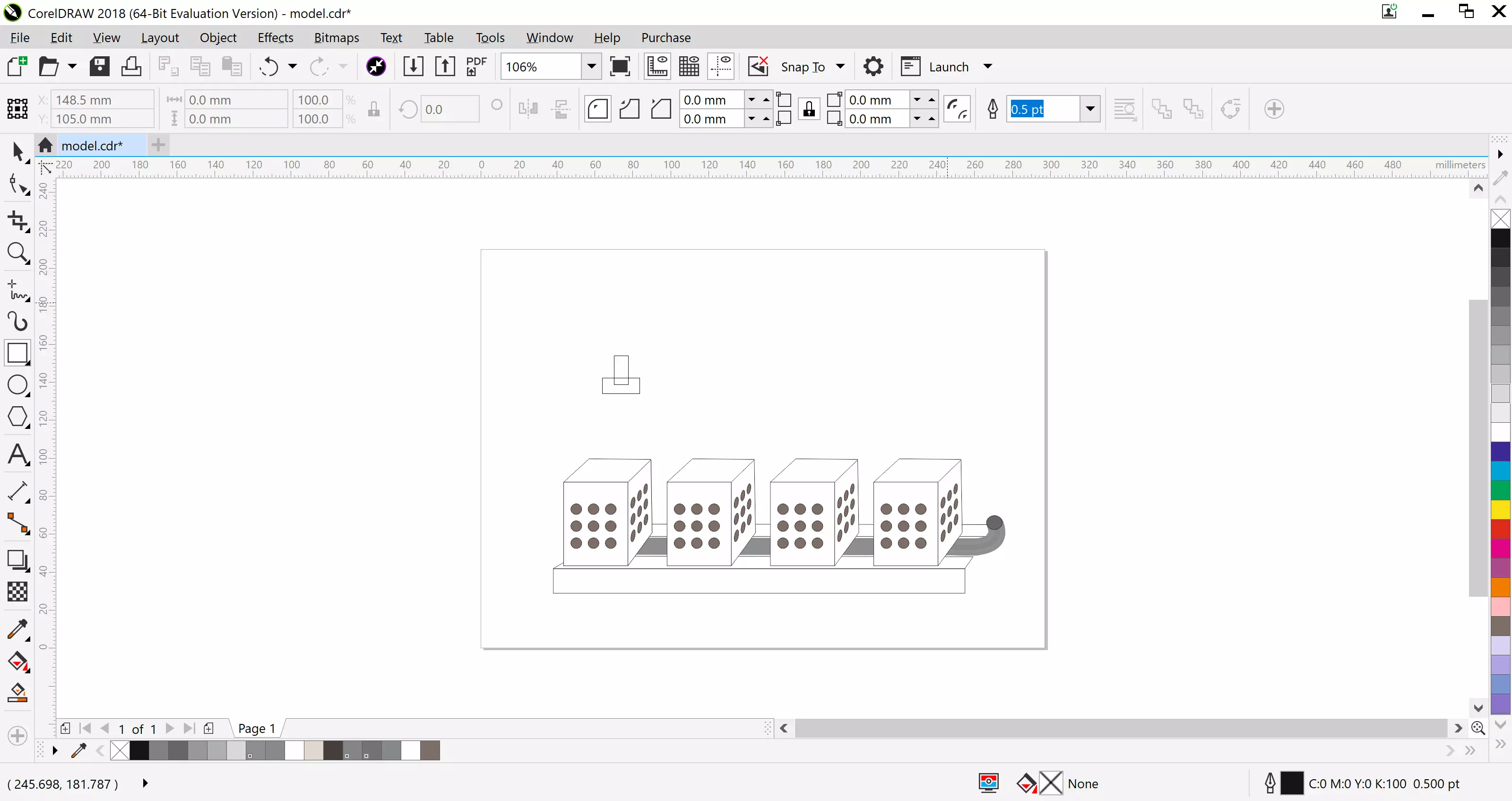
Create two overlapping rectangles, this is your bracket.
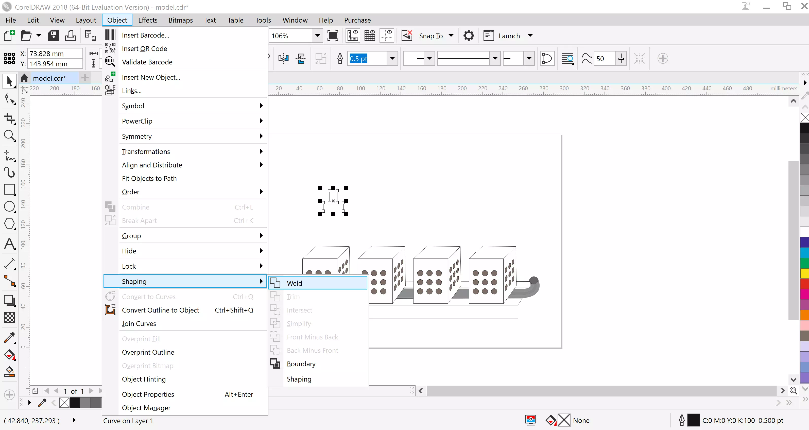
In the object tab, click on the two rectangles, in the shapping tool click the weld option, this should join the two rectangles together.
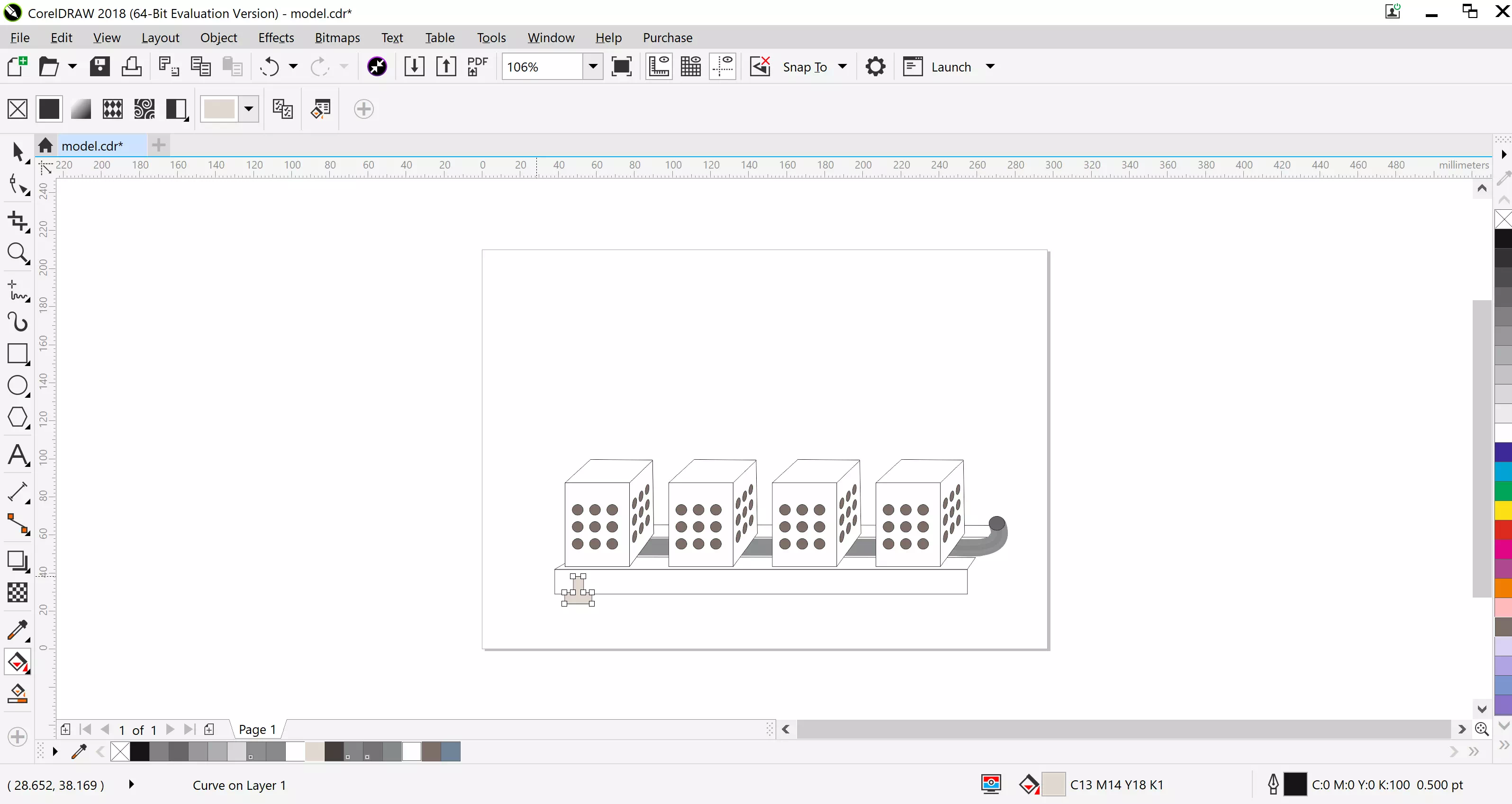
Move the bracket the bottom of the base and color it using the fill bucket, resize if needed.