Eighth assignment
6 March 2019
Make something big
Plywood furniture
design
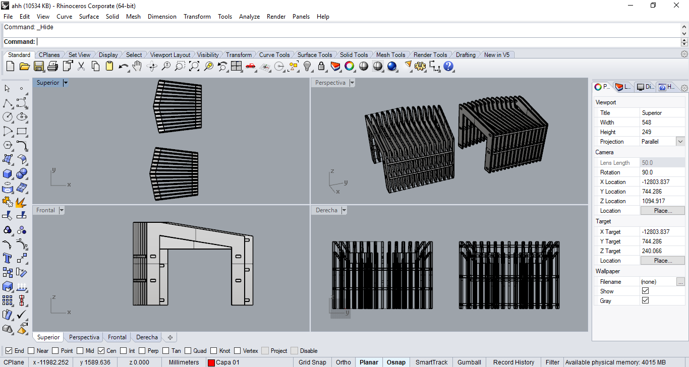
The software that I used for this assignments was Rhinoceros.
I have seen so many parametric plywood furniture with crossing sections, but for me I wanted to tried something a little different. I designed this street furniture to be modular that is why it needed some angle for the sides to work as it was thought.
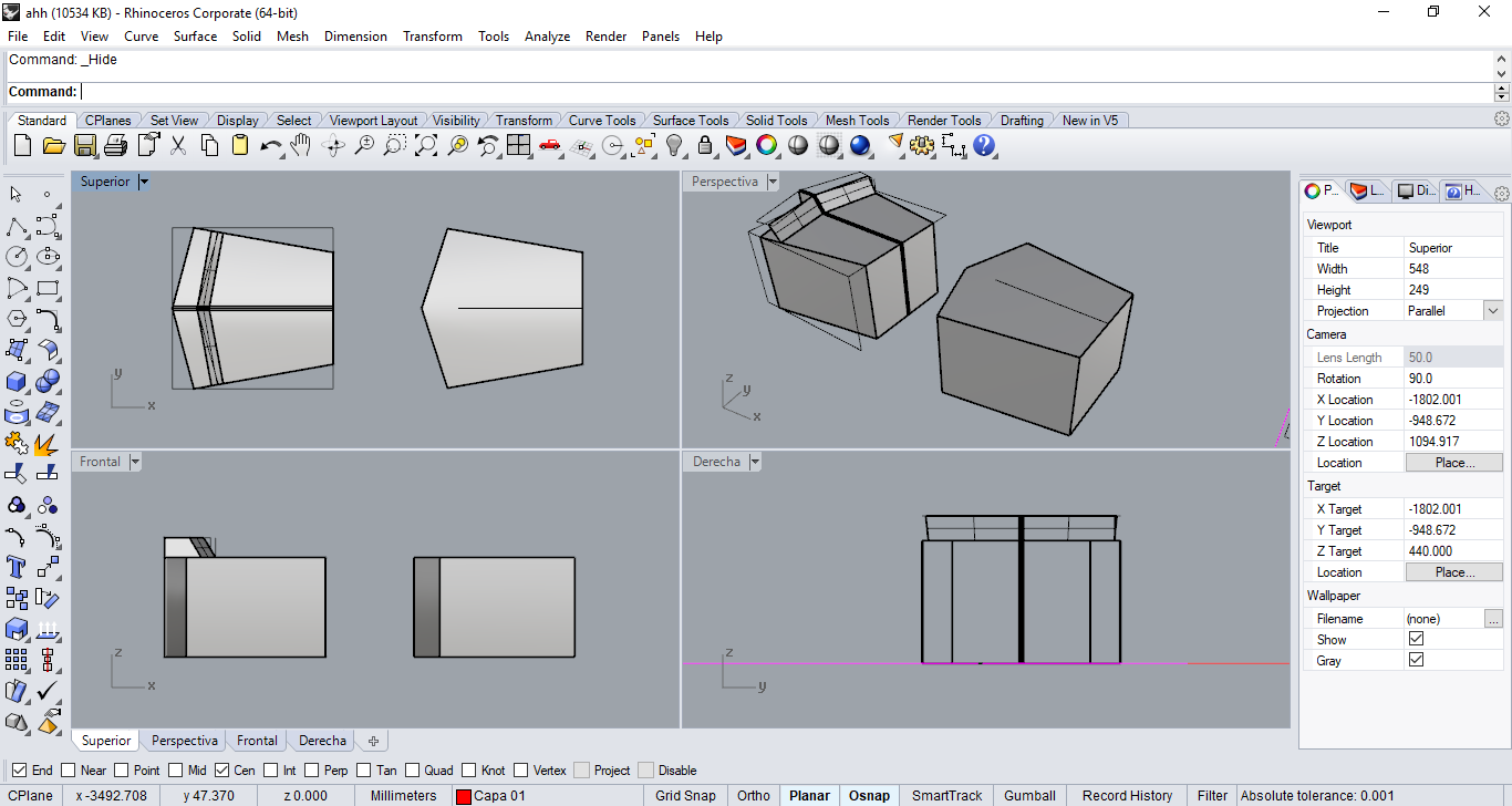
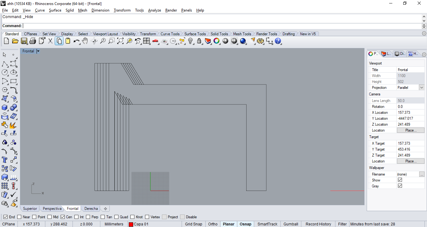
I started by making the overall body.
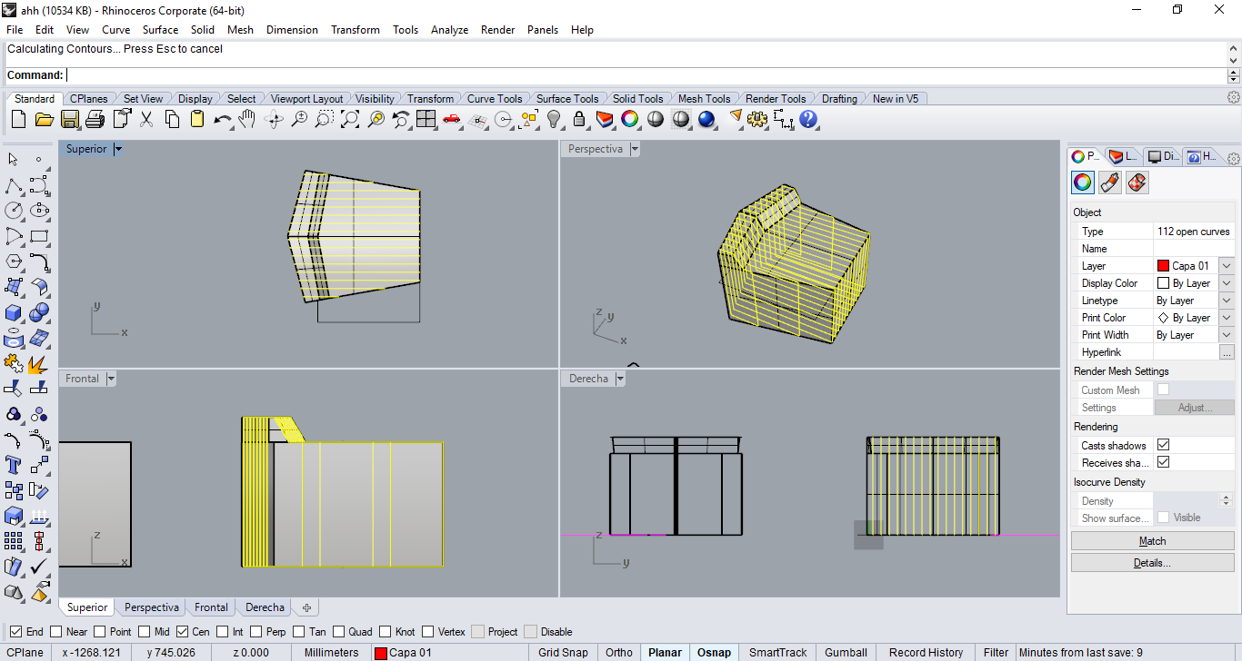
Then I used the contour command to create the sections needed to construct the volume with crossed wood profiles.
Usually I would leave a 30 mm space between each profile, the material that is going to be used is 15 mm thick, but I needed to reduce as much material as possible so I tried with a 40 mm gap.
I wanted it to be completely symmetrical, that is why I erased half of them, leaving the bigger one as the center.
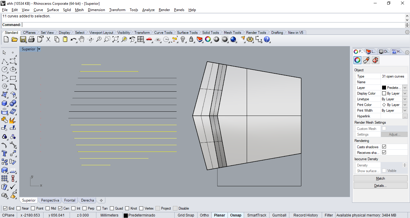
I made the contour for each section to be able to extrude them later.
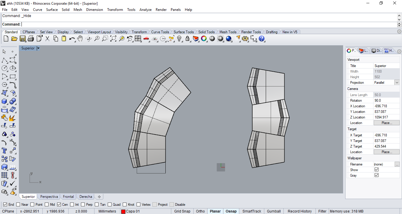
After this, what I did was rotating each profile to create that angle, even though I wasn't sure I was going to be able so assemble it.
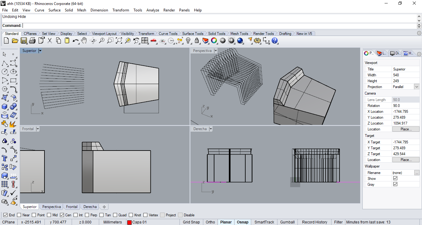
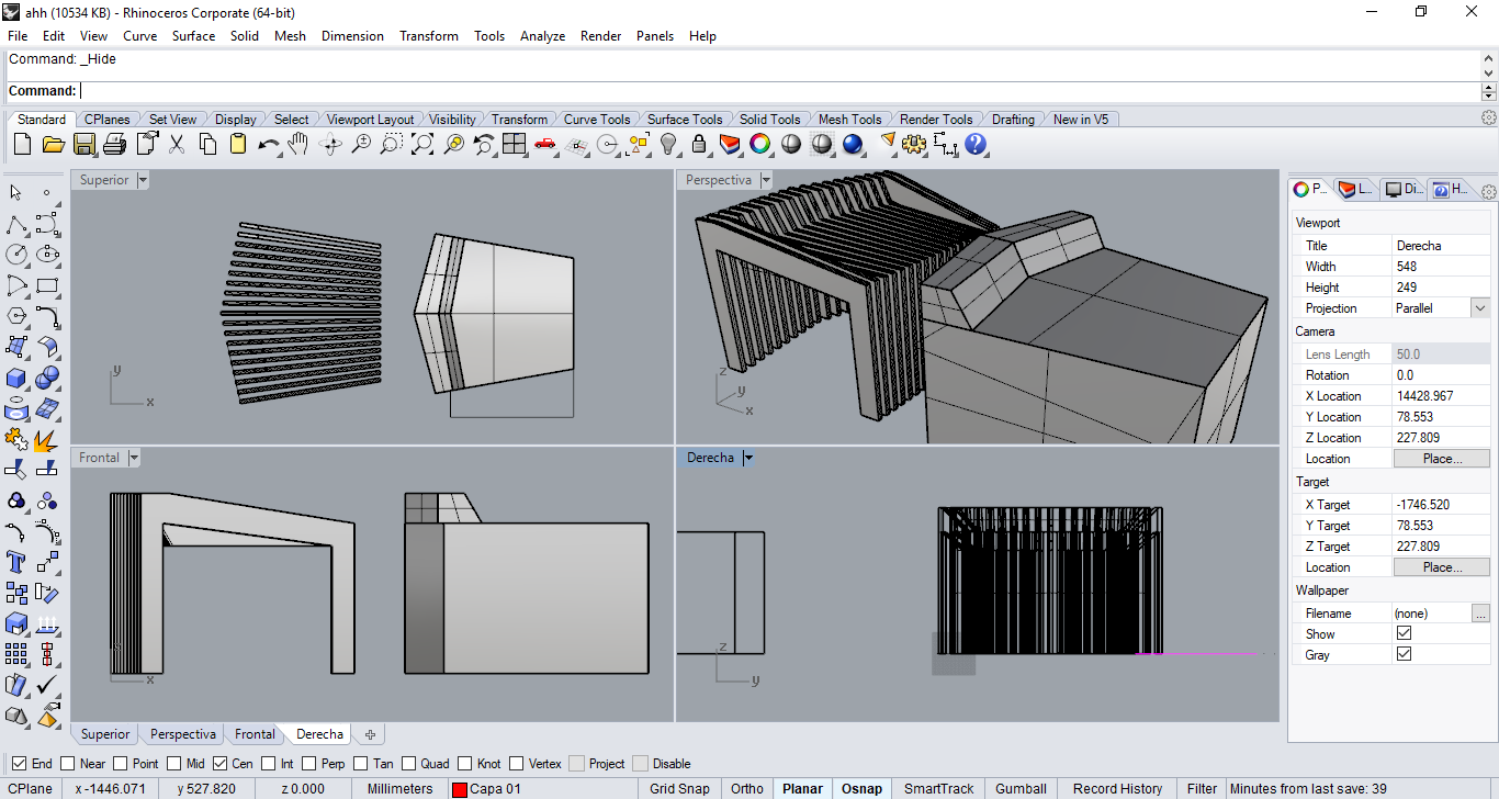
Finally I extruded all the closed curves 15mm.
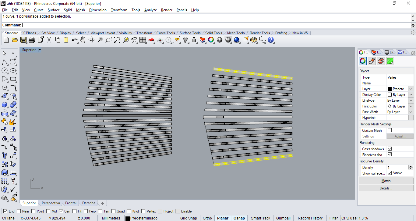
Here you can see the difference between the 30 and 40 mm gap (when running the contour command). The one with the 30mm gap has 19 pieces while the other had 13. In order to reduce the amount of material that I was going to use I gave up some degrees for the sides but added one extra piece each side, so the seat would maintain it's width without having to increase the gap and make it uncomfortable.
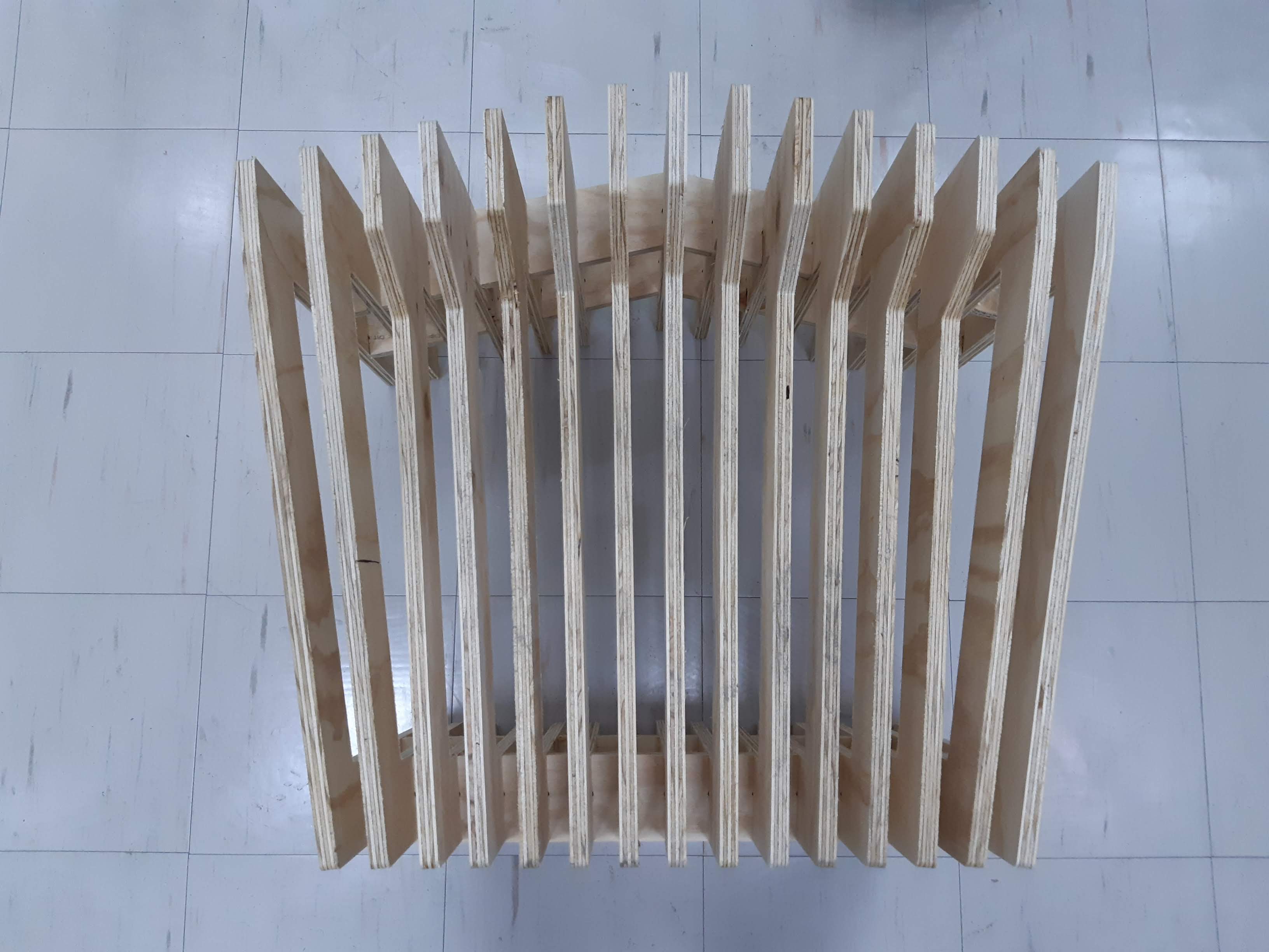
Finally for the building part I added the crossed sections.
I have some experience with cnc machining, so unlike laser cutting tolerances here are different. When cnc machining, pieces turn out to be exactly the measure we give them. Unless you enter the wrong endmill information. For this part I just modeled the exact sizes without adding or removing even 0.01 mm.
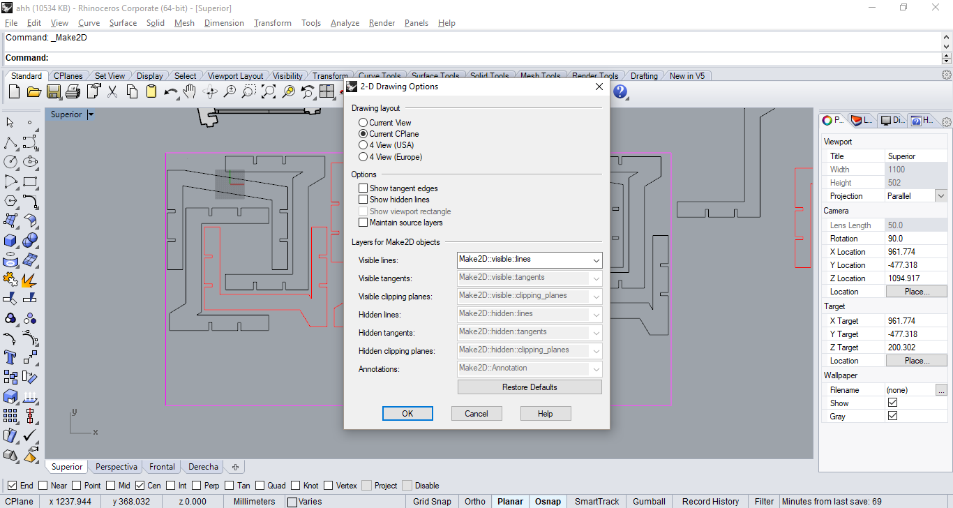
Now it is time to make the 2d design and fit the pieces into the wooden board. The command for this is Make 2-D drawing
The gaps as I said before are exactly 15 mm that is the thickness of the material I was going to use.
I also laser cut the pieces in a smaller scale, adding the tolerance for laser cutting of course.
fabrication
THE MACHINE
At TECSUP we have a SHOPBOT PRSalpha 96-48. You can also check the ShopBot User Guide.
Working space: 2400 x 1200 x 200 mm
General dimensions: 3048 x 2001 x 17000 mm
Step resolution: 0.0127mm
Positional accuracy: +/- 0.076mm
Z-zero Touch-Off Plate and XY Proximity Switches
Linear Cutting Force: Aprox 68 Kg
TOOLPATH AND PARAMETERS
The way we tell the machine how it should work and the paths it should follow is by generating a toolpath.
For the Shopbot that is available in Fab lab Tecsup we use Vcarve ShopBot edition
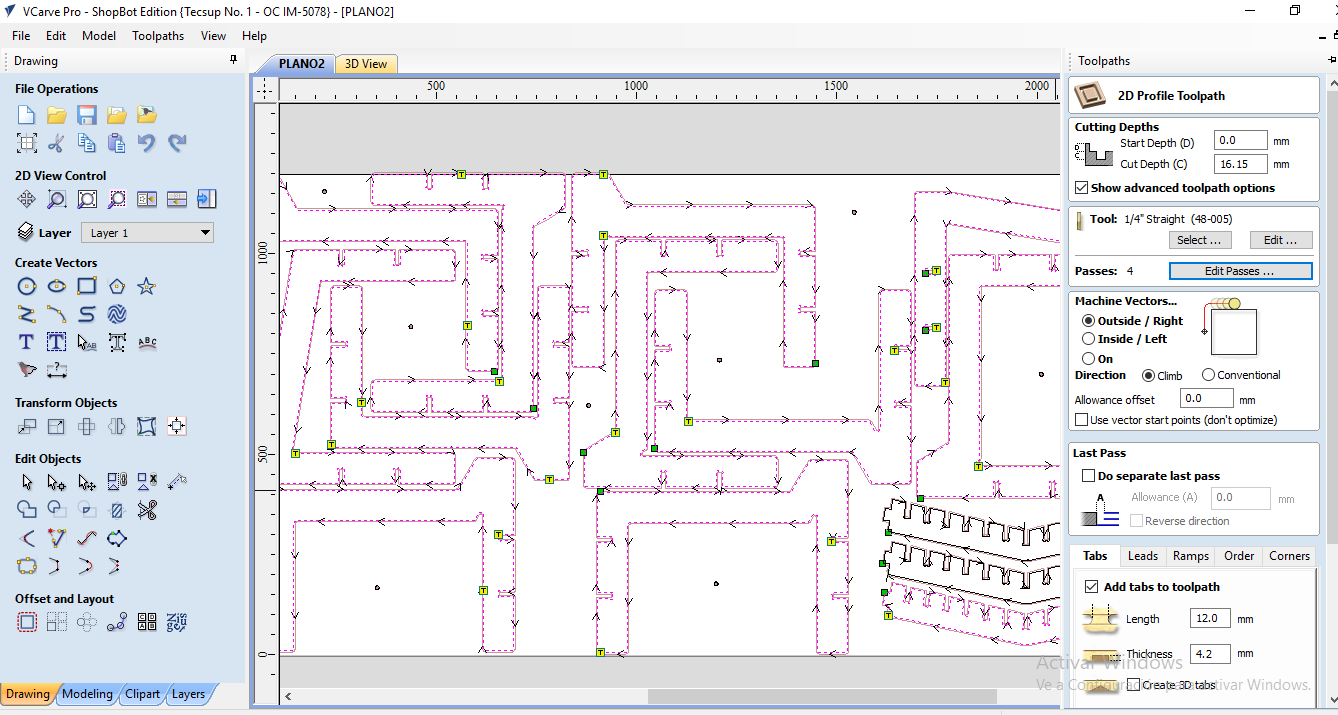
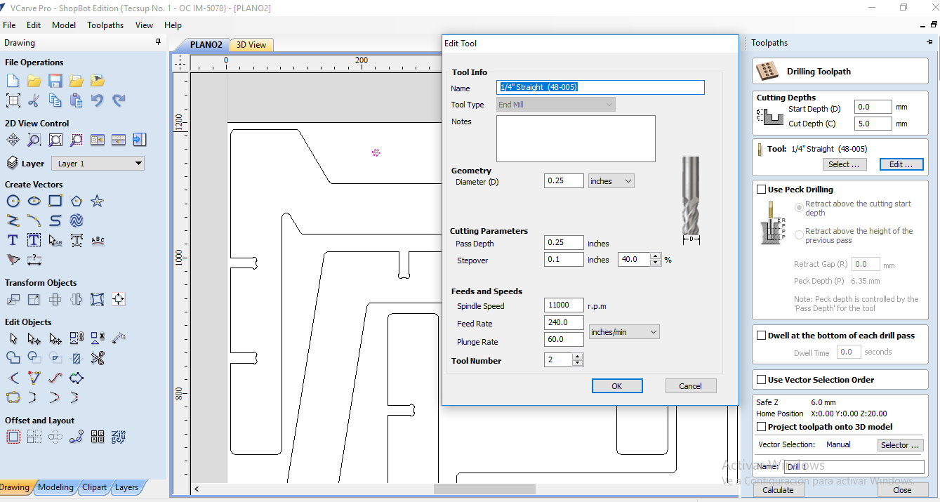
After setting the dimensions of my material and importing my file, the first thing I did was specify start depth (0 mm) and cut depth (16.15 mm)
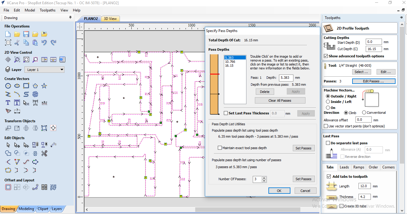
Then I set the depth for each pass, in this case they were 3 passes of 5.383 mm each.
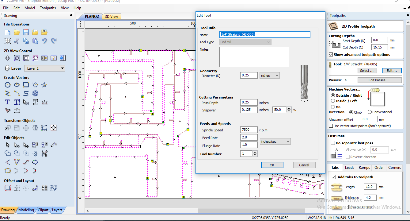
After that I edited the tool info. In this case I am using a 1/4" flat endmill
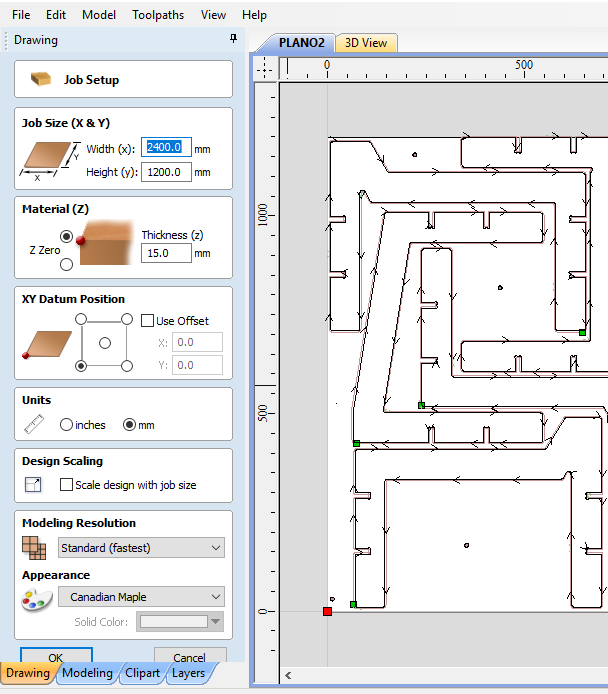
Make sure job set up information is correct, this is the setting I used.
You can use this Fablab Speed and Feeds Calculator to achieve the best results. Also if you are a new to all this terms you can check this video.
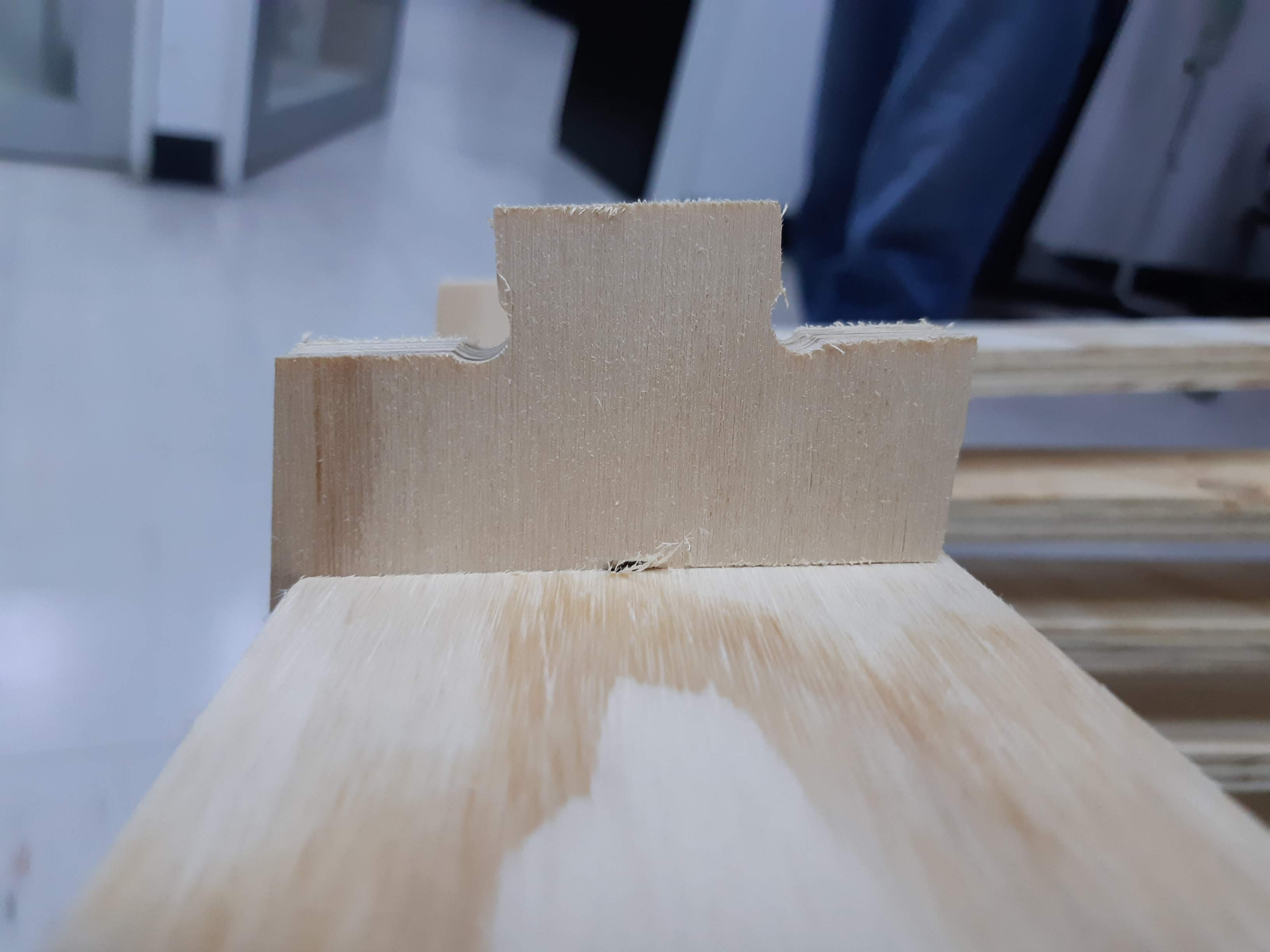
And don't forget to edit corners of joints so the fit, a common endmill can't machine square corners.
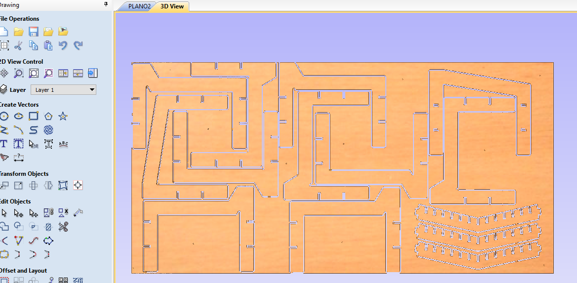
This is the 3d preview the software generates for the toolpath.
I generated the drills and repeated the same process with the same endmill to attach the board to the platform.
Vcarve generates a file that we need to import then to the Command console.
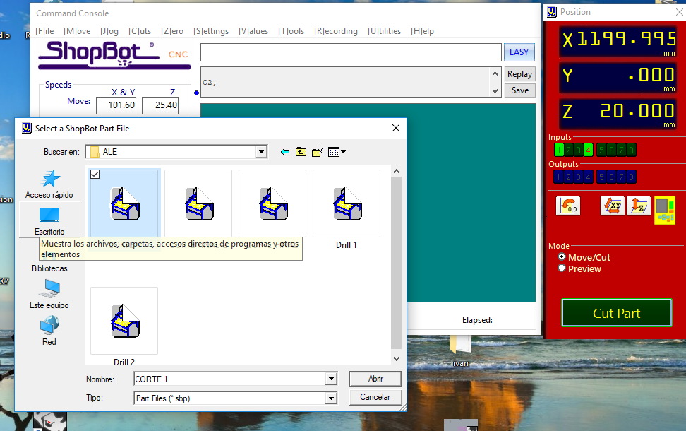
I started with the drills and then with the profiles for my project.
First I set the = for x and y.
(That warning always appears because we work with the metric system)
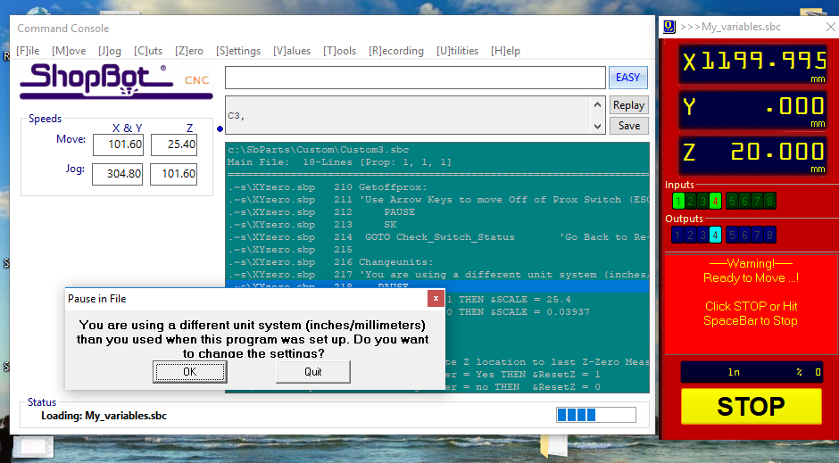
Then we set the o for Z
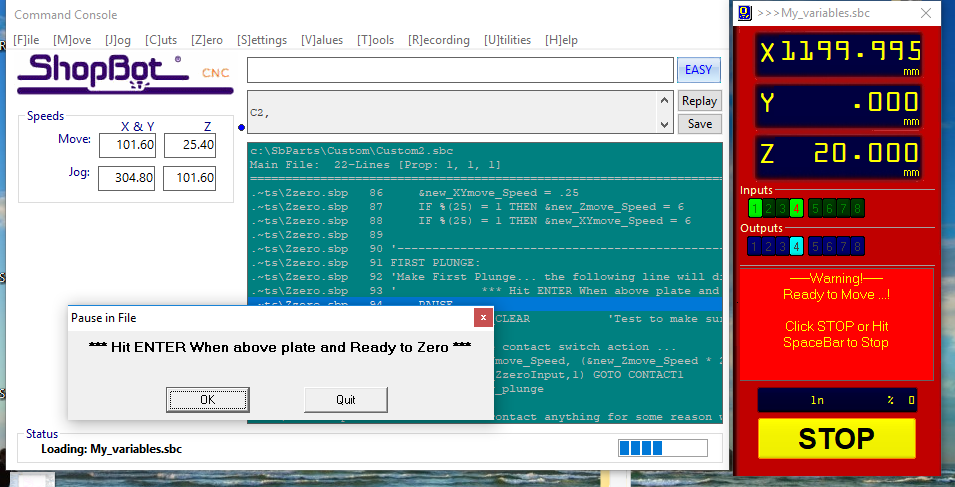
This is probably even more important than x and y because if you fail or don't read the warning and just hit 'ok' file may be send and you can broke your endmill.
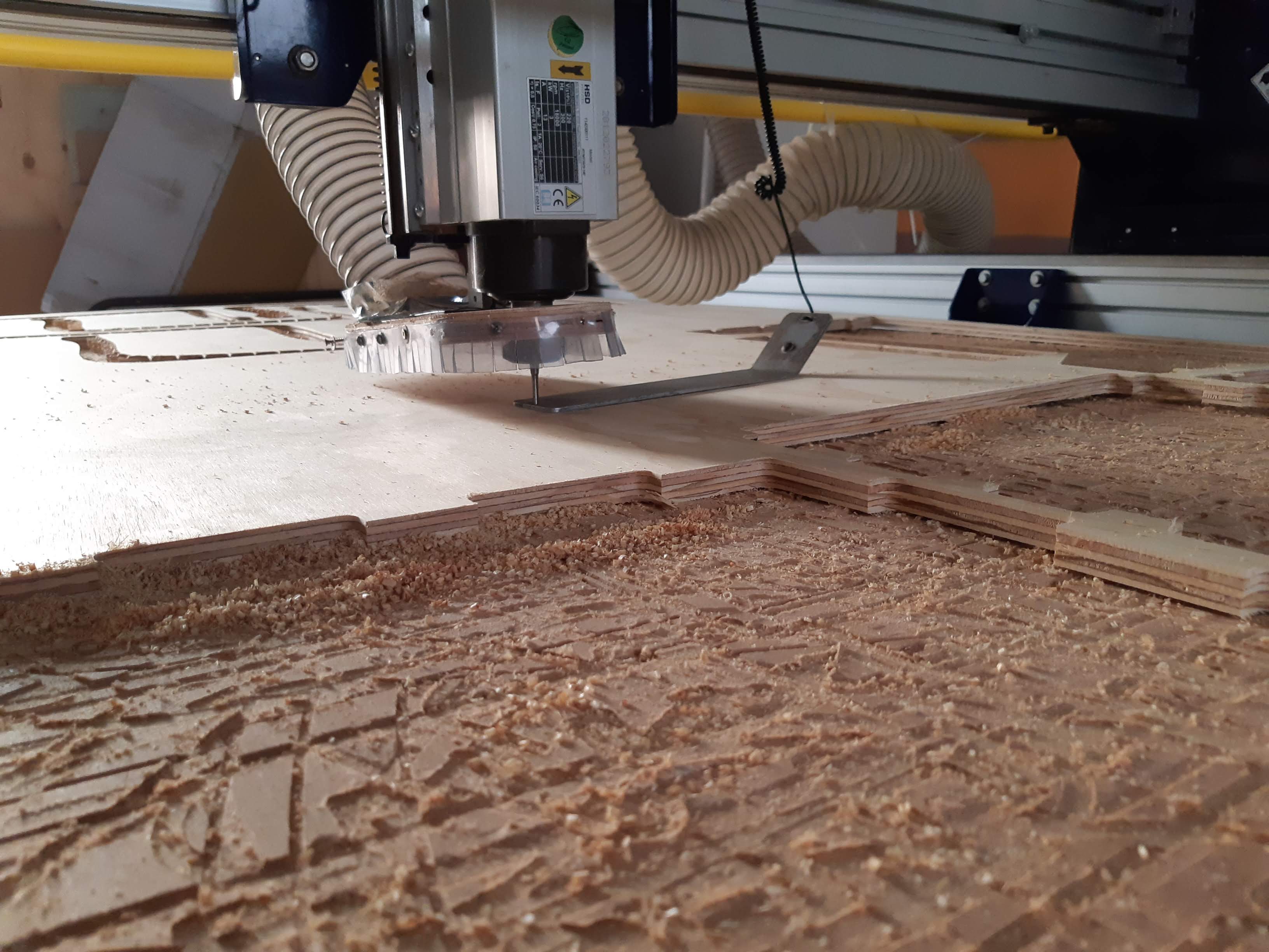
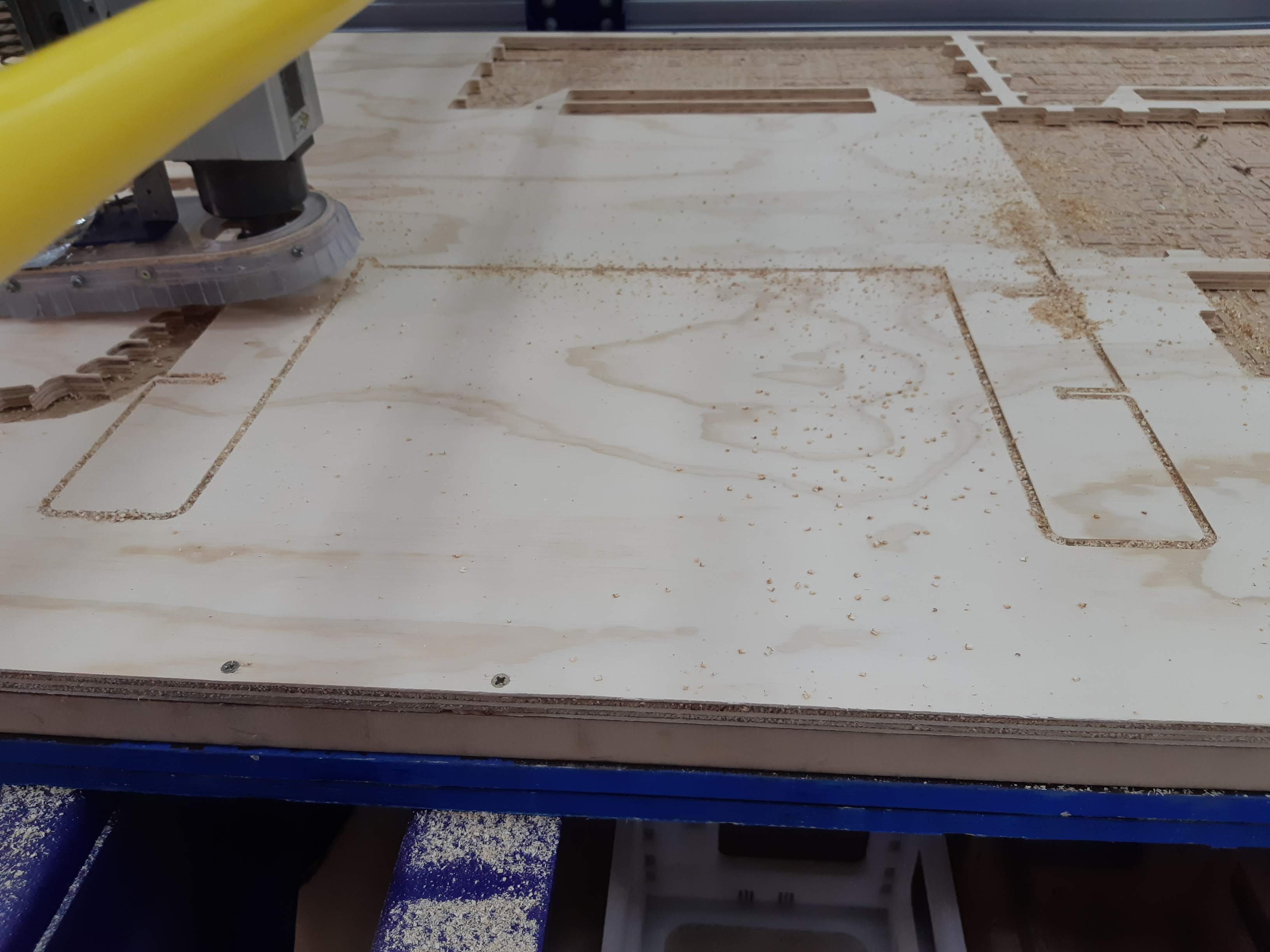
After all these steps I was finally cutting my pieces
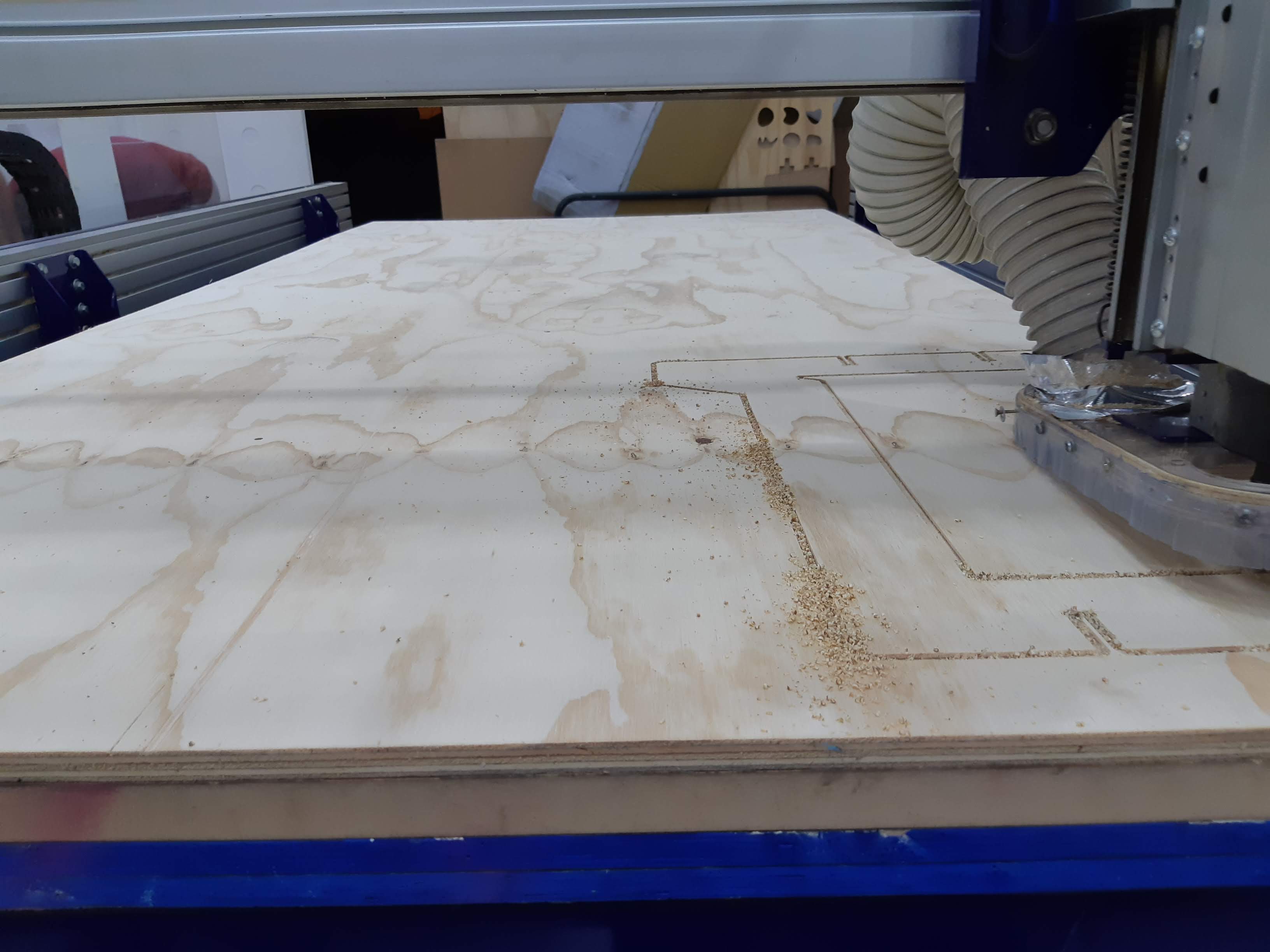
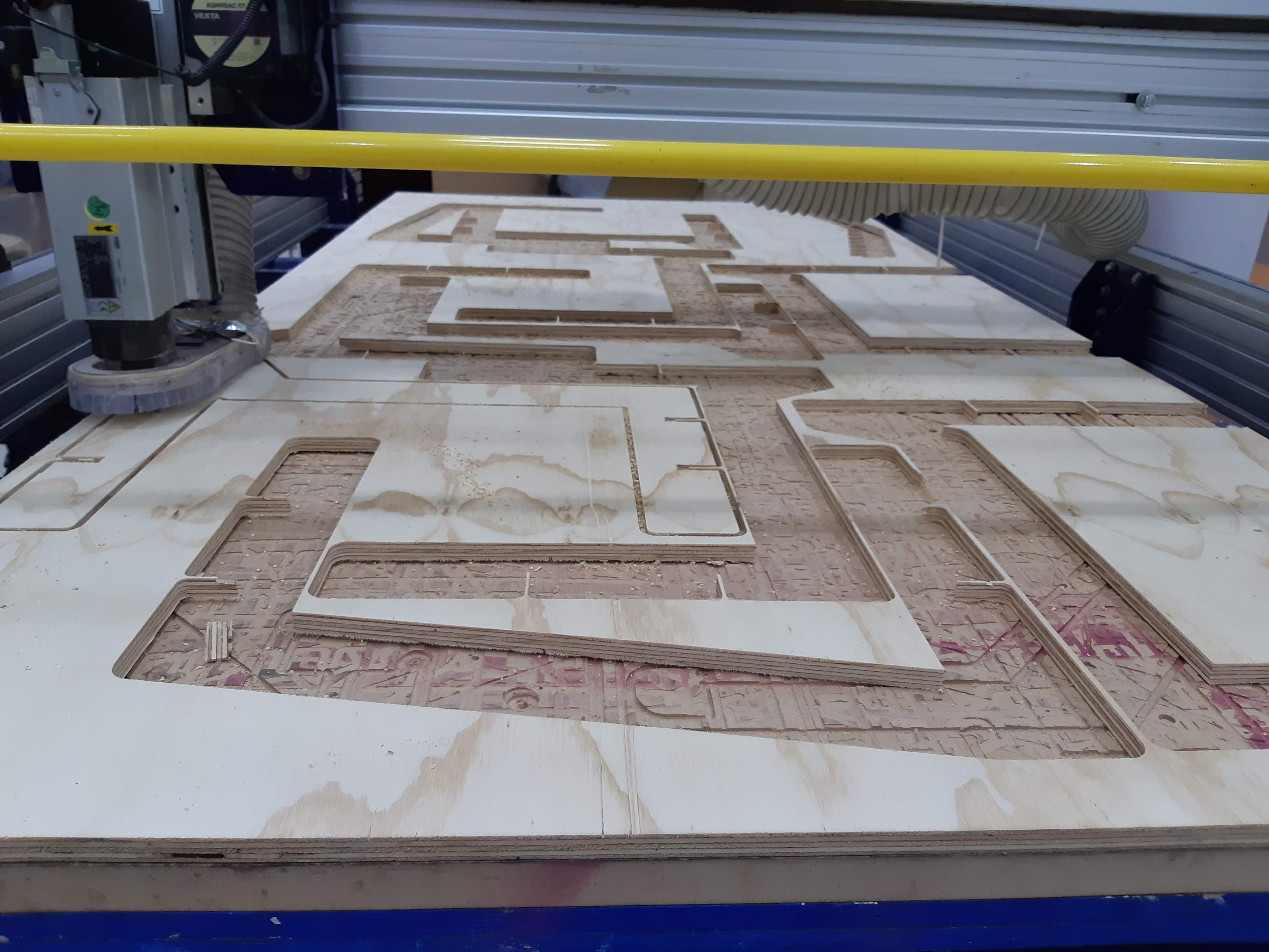
This is the joints corners I explained before you need to edit for it to fit. It is a very important step.
CNC cutting is very precise, I've had some little experience with it before, that is why I didn't work with tolerances. Although I worked with some angles, fitting and assembling for me was as easy/difficult as my classmates. We just needed to add a little pressure, and you may want to use some small piece of other material in the middle to avoid hitting and damaging your project.
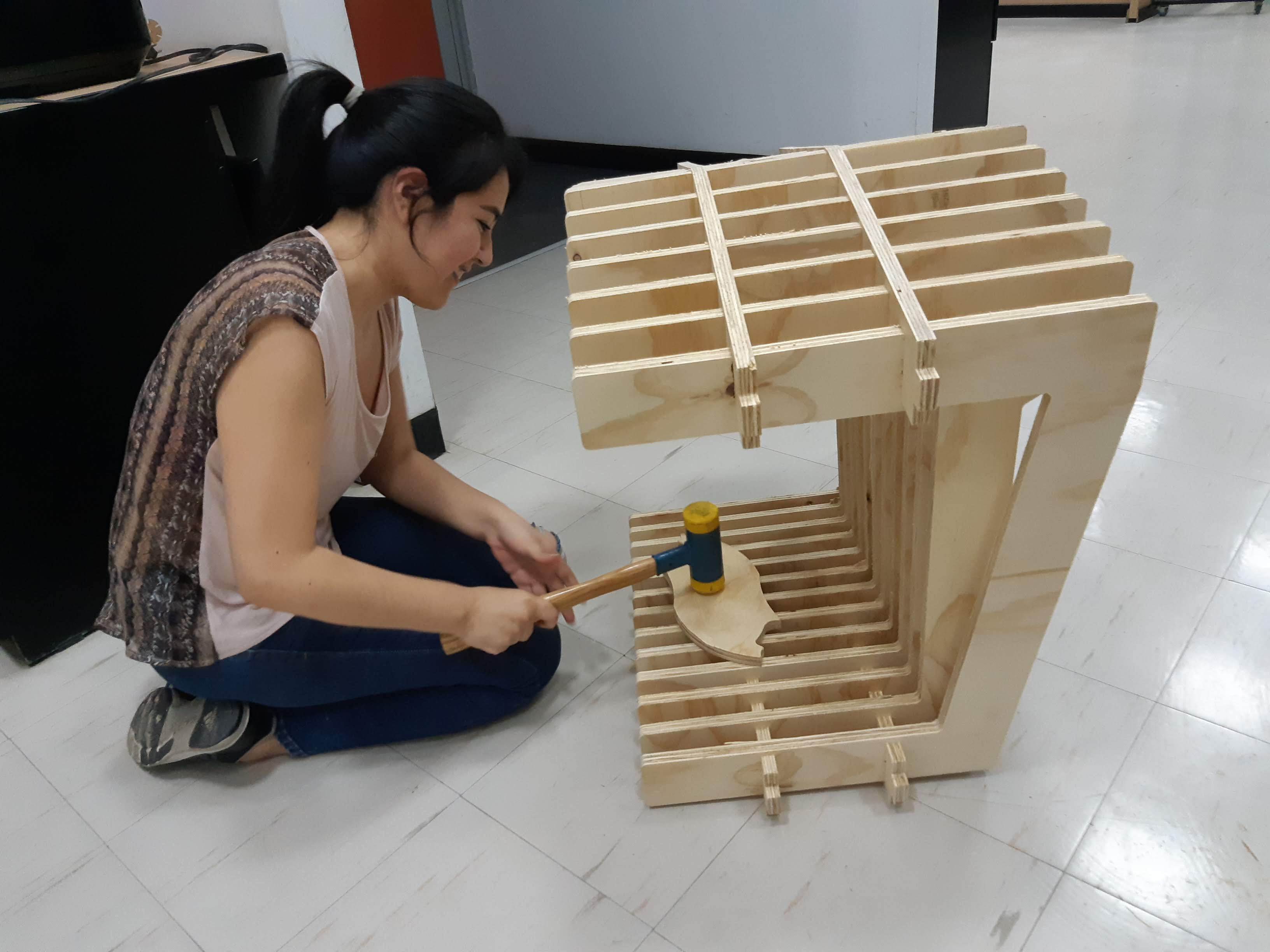
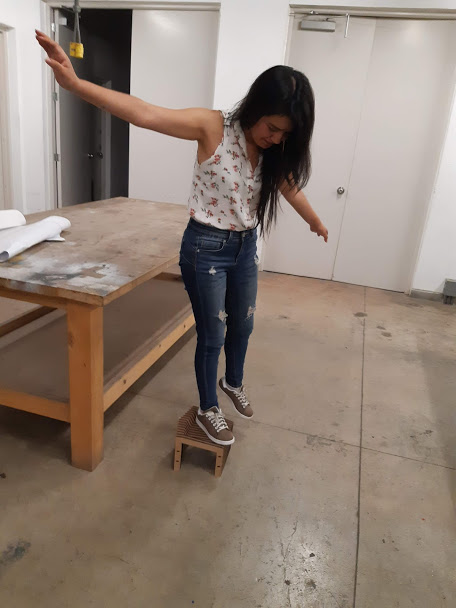
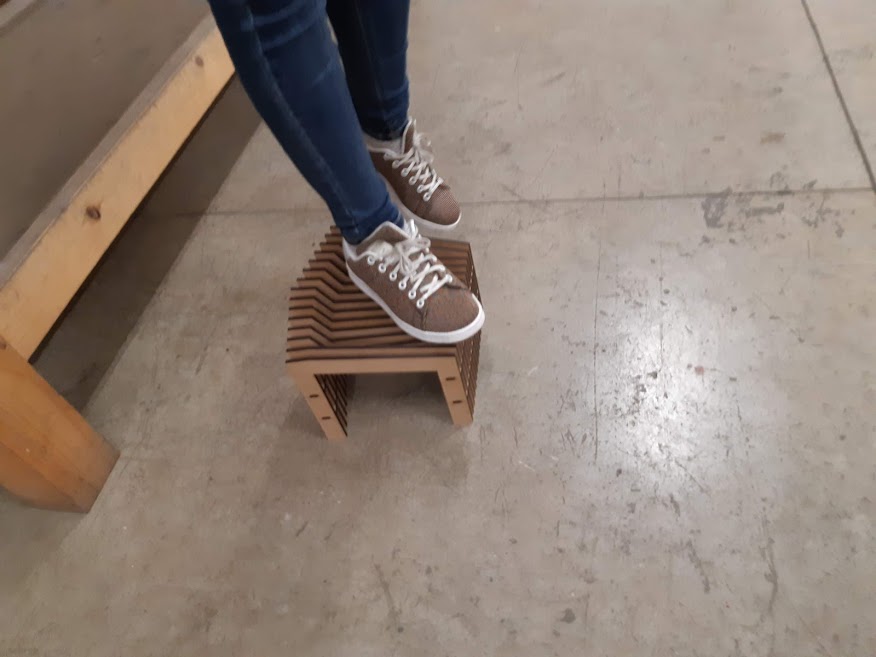
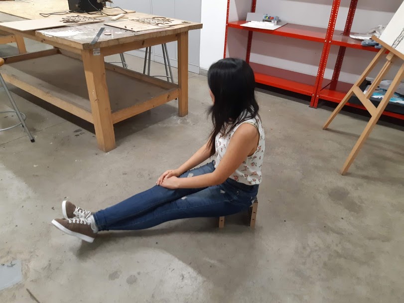
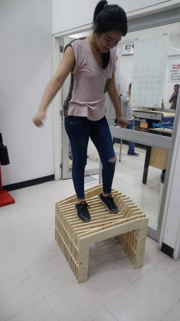
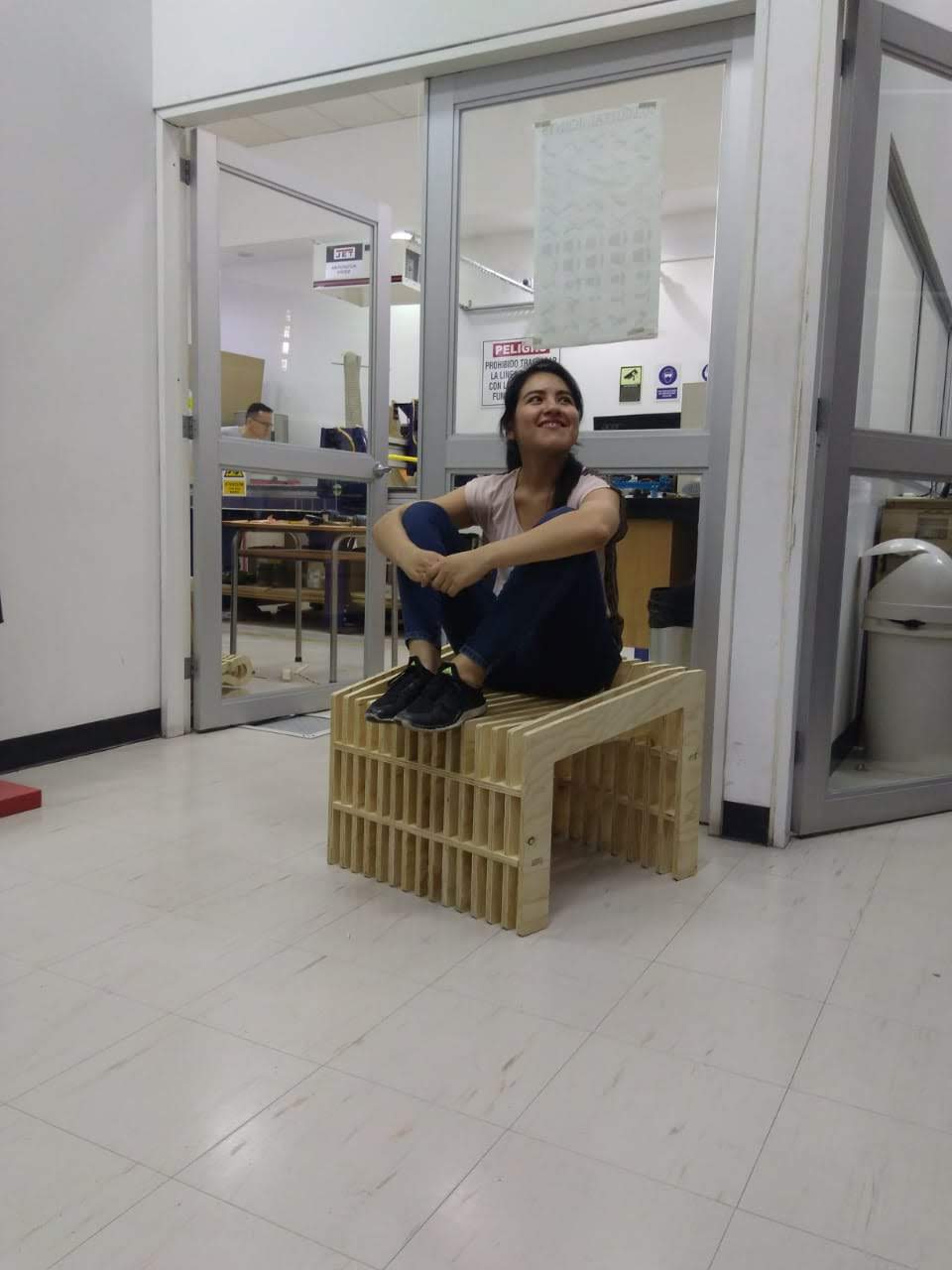
Everything worked perfectly!!
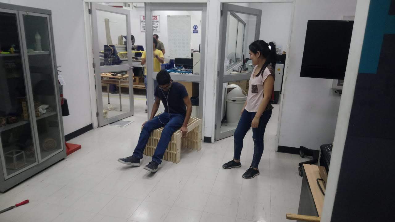
And it was VERY resistant.
DOWNLOAD