Fourteenth assignment
24 April 2019
Part I
Design, build and connect wired or wireless node(s)
Part II
Send a message between two projects
Week's assignment
This weeks individual assignment was to design, build and connect wired or wireless node(s) with network or bus addresses and the group assignment was to send a message between two projects.
I will be showing you the group part below and you can check the indivial assignment in part I.
For this assignment worked with my classmate Abdon he also did Neil's example for Serial bus
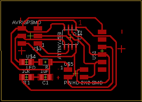
Board design
My board

Connections are very important since we don't want to make a mistake and burn our microcontroller (I actually connected them wrong and almost burn mine)
If you compare both designs, they are really different. My FTDI header is rotated 180° compared to his
Once the bridge is connected correctly we need to make sure we connect the nodes right, the correct orientation for the ISP as well.
Abdon's board
check operation
serial communication
To check the operation I connected the bridge board to the computer through the FTDI. Then I opened the serial monitor and started entering the 3 different values that were assigned to each board to see how it was working.
For every interaction the three lights (one from each board) lit up at the same time. Then one of them lit up right away. This last blink depends on what number we enter in the monitor.

As you can see, just two of the LEDs were blinking but the bridge was working just fine transferring data. Because of this we can assume that the problem was just the LED, and it was. As i wanted to use different colors for each board, some of them had the GND marked differently and as the multimeter wasn't working properly I decided to give a shot but I ended up making a mistake when soldering. To fix it I just had to turned it around.
I connected it again and IT worked just perfectly.