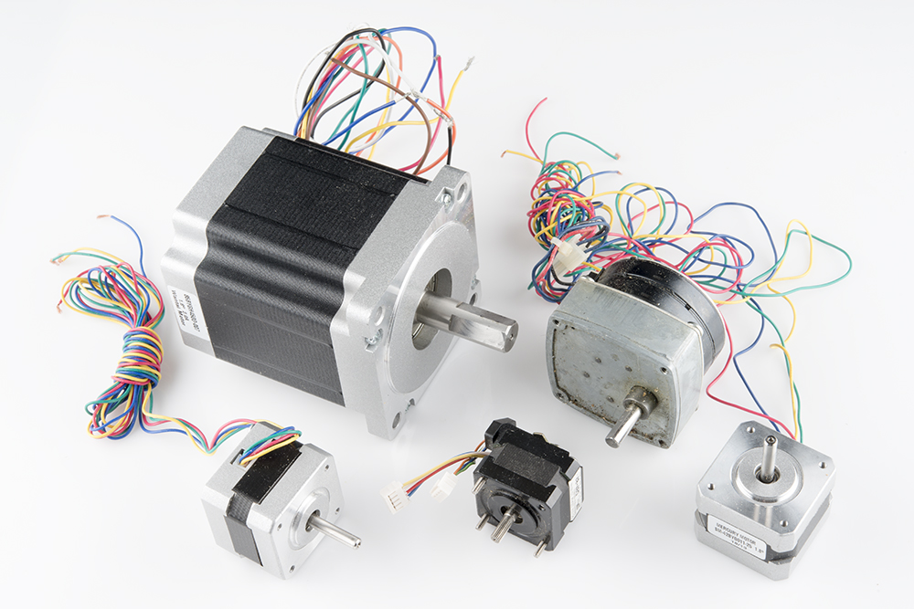
OUTPUT DEVICES
The objective of this week is to know the operation of the different types of output devices.
1. Group Assignment
measure the power consumption of an output device
2. Individual Assignment
Add an output device to a microcontroller board you've designed, sand program it to do something
2.1 What is the microcontroller?
A microcontroller is a compact integrated circuit designed to govern a specific operation in an embedded system. A typical microcontroller includes a processor, memory and input/output (I/O) peripherals on a single chip.Sometimes referred to as an embedded controller or microcontroller unit (MCU), microcontrollers are found in vehicles, robots, office machines, medical devices, mobile radio transceivers, vending machines and home appliances among other devices (MORE ABOUT IT)
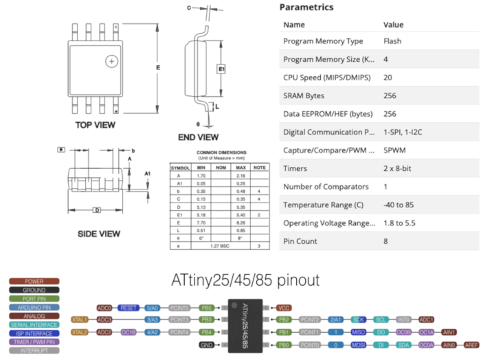
2.1.1 ATtiny25 / ATtiny45 / ATtiny85
ATtiny (also known as TinyAVR) are a subfamily of the popular 8-bit AVR microcontrollers, which typically has fewer features, fewer I/O pins, and less memory than other AVR series chips. The first members of this family were release in 1999 by Atmel.Check "
_
2.1.2 Bord Design
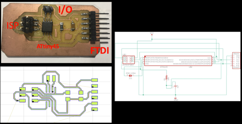
For this week I continue using the design of the card that I used in the week of "input Devices".
This design allows me to obtain two outputs that I can use to control an engine.
2.1.3 Controlling a motor
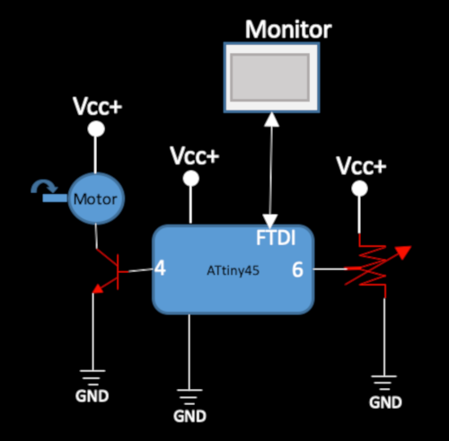
To control an output device (motor). I used the card that I designed in
To see the change in speed, I had to use an
_
This is the programming code to be able to control the speed of the motor. This must be loaded through arduino.
          #include SoftwareSerial.h
          SoftwareSerial mySerial(11, 2); // RX, TX

           int motor = 1;       // pin to which LED is attached
           int botton = A2;      // analog pin to which potentiometer is attached

          void setup() {

          pinMode(motor, OUTPUT); //sent the pin as an output
          pinMode(botton,INPUT_PULLUP)

           }

         void loop() {

       mySerial.begin(9600);         //start the serial software comunication
          value = analogRead(pot);      // reads the value of potentiometer (ranging from 0 and 1023)
          mySerial.print("sensor = ");  //message
          mySerial.print(value);        //message
          outputValue = map(value, 0, 1023, 0, 255); // scale it to use it with analogWrite
          analogWrite(motor, outputValue);             // set the analog out value
          // print the results to the Serial Monitor:
          mySerial.print("\t output = ");
          mySerial.println(outputValue);
          delay(2);                            // wait for 2 milliseconds for
          // analog-to-digital converter to settle
        }
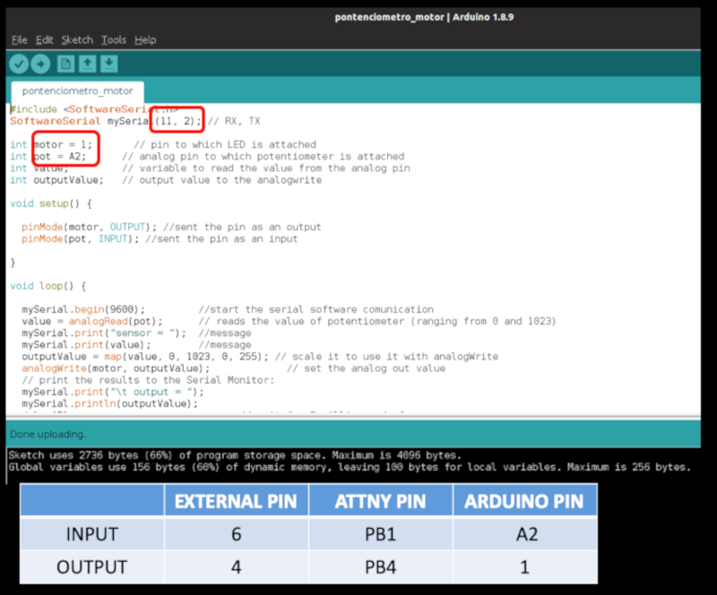
I had to change the microcontroller pins according to the configuration according to "arduino".
_
In this scheme you can find the distribution of all the pins.

_
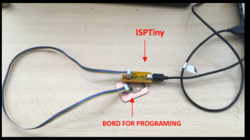
I connected the bord to the ISP programmer, and this to the pc.
_
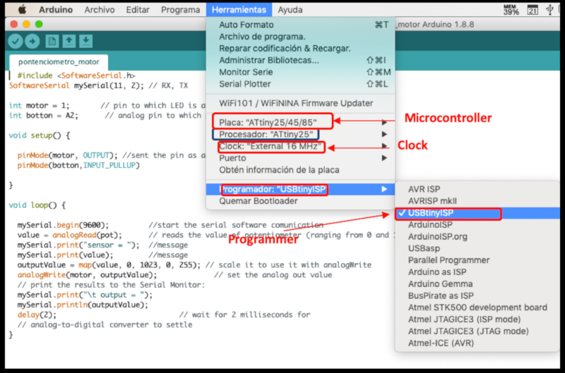
To be able to carry out the programming it is necessary to carry out the configuration of the card and the programmer through arduino.
2.1.4 Results
The speed control of the motor is done through the pontenciometer. I observed the change of speed on the screen through arduino.
SELF EVALUATION
WHAT WORKED:
- I probe with a output device.
- I verified the connection characteristics of output device.
- I used an interface, where I could see through the computer how these motor act.
WHAT DID NOT WORK:
- I could not try other types of output device. Because we did not have available in the lap or why they need to make another electronic bord.
THINGS TO IMPROVE:
- Control my time.
- Learn more about the operation of other types of output device. That will be useful for my final project.
Contact Me
Feel free to contact me via email or phone.
 FabAcademy 2019