
Fab Academy 2019 - Lucas Lim
09. Embedded Programming
09. Embedded Programming
Group assignment:
I am from an IT background, but this week lesson on “embedded programming” is a bit confusing and too overwhelming for me as I am new to the AVR microcontroller environment.
My week :
At first though, this week we do not fabricate anything in Fab Lab, it mainly dealing with software programming. So I spend time doing a bit of reading, since this week assignment is about 'reading'. I bought a book on AVR programming from our local 'Kinokuniya' online book store. Also borrowed some books on AVR programming from the library.
The AVR tutorial listed on class site is very helpful too.
My instructor, Mr Steven, had passed to me a 'BBC micro:bit' to play around with over the weekend and it had been a useful device to get started in programming and understanding of what a microcontroller can do.
The learning outcome are :
- Understand other type of microcontrollers and its architectures
- Understanding more on AVR microcontrollers - by reading the datasheet
- Try different ways to programming the AVR microcontroller
- Learning to program my hello world board to do something
- Learning C programming language
Misc :
- Learning to capture video and embed the (.mp4) video onto my website.
- Learn to store large video files on remotely file sharing server
- Learn to use a HTML formatter call "Prettify" to display my coding
Computer :
A computer or a notebook contains a CPU (processor) and is the brain which runs the program and does all the computing (or making the decisions).
Computer Architecture (base on Intel® architecture) :
The CPU is connected to a 'hard drive' where the program is stored as well as the OS and the data. The harddrive is a 'non-volatile' storage media which means when the power is turn-off, the data would not be lose. When you run a program, the program is transfer from the harddrive via the 'system bus' and load onto the RAM chips (temporary storage for data/instrcutions) before sending to the CPU for processing/computing. RAM chips are volatile memory and lose the program/data when the power is switched odff.
Image from 'Computer Architecture Course Website'
@ https://www.doc.ic.ac.uk/~eedwards/compsys/
In the Fab Lab, we are using AVR microcontrollers which are low cost alternative to the costly Intel® CPU. Microcontrollers are commonly found in embedded systems, and popular among hobbyist and educational instituions. Why put a costly Intel® CPU into a vending machine, a microwave oven, or other consumer devices?
| Microcontroller | A microcontroller is essentially a tiny CPU with integrated memory or peripheral devices. The program is store in the non-volatile Flash memory inside the microcontroller. Microcontroller is widely used in embedded systems. |
| Microprocessor | A microprocessor is also a tiny CPU but require (or use) external chips for memory and peripheral interfaces. A microprocessor is usually faster than a microcontroller and runs at a speed of 1GHz and above. Therefore it is used for the larger embedded system. |
| An embedded system | is simply defined as any computing system contained within a product that is not described as a computer. Embedded system is designed to perform a specific task and cannot be use like a general computer to run other different computing tasks by other programs. Embedded systems are found in consumer electronic devices/gadgets (like microwave oven, digital timer, etc) to more complicated embedded systems (like gaming consoles) and even major factory and other industrial systems. |
References :
- Understanding Embedded Systems - the basics (by electronics-notes.com)
We are "spiraling" back on the topic of electronics.
In week 5, I had fabricated a 'FabTinyISP' which used an ATTiny45 chip. In Week 7, I had fabricated a 'hello world' board which used an ATTiny44A. The popular 'Arduino Uno' board is using an ATmega328P chip. All these chips belong to the AVR family of microcontrollers.
| ATTiny44A | ATTiny45 | ATmega328P |
|---|---|---|
on my Hello World board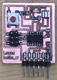
|
on FabTinyISP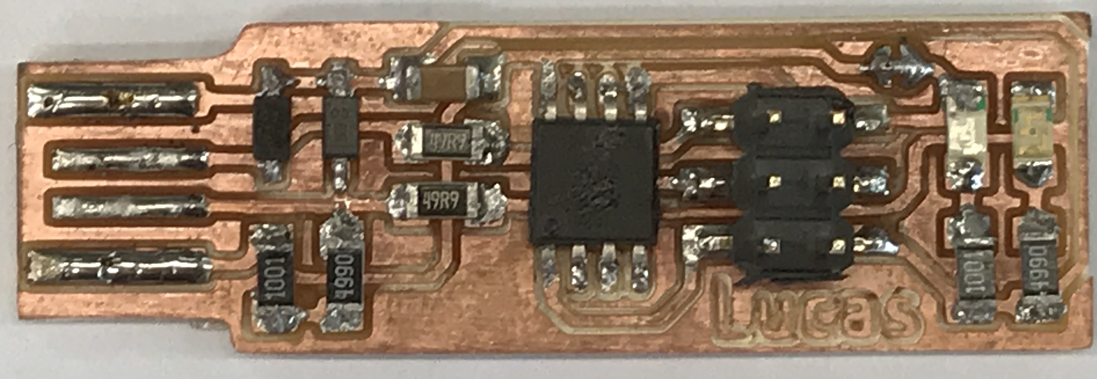
|
on my Arduino Uno Rev3 board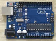
|
| Part No. ATTINY44A-SSU-ND | Part No. ATTINY45V-10SU-ND | Part No. ATMEGA328P-AU-ND |
| Datasheet | Datasheet | Datasheet |
| Core Processor : AVR | Core Processor : AVR | Core Processor : AVR |
| Speed : 20 MHz | Speed : 10 Mhz | Speed : 20 Mhz |
| Architecture : 8 bit | Architecture : 8 bit | Architecture : 8 bit |
| Number of I/O : 12 | Number of I/O : 6 | Number of I/O : 23 |
| Flash : 4KB | Flash : 4KB | Flash: 32KB |
| SRAM : 256 | SRAM : 256 | SRAM : 2K |
| EEPROM Size : 256 | EEPROM Size : 256 | EEPROM Size : 1K |
| Price : SGD $1.10 (immediate stock) | Price : SGD $2.23 (immediate stock) | Price : SGD $2.05 (immediate stock) |
| More info on Digikey | More info on Digikey | More info on Digikey |
Differences between three AVR microcontrollers are in 'bold' text.
Brief specs and price are from DigiKey website @ https://www.digikey.sg.
Before you use a microcontroller or any electronic component, the very first step is to have a look at the datasheet of that component. The datasheet is like an instruction manual and explain what the features available, what they does and how to (correctly) use them.
The ATTiny44A datasheet is a large manual of 286 pages long.
This is my first time reading a datasheet. I briefly fliped throught the pages and list down some of the interesting information available inside the datasheet :
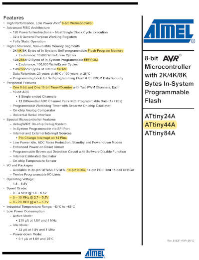
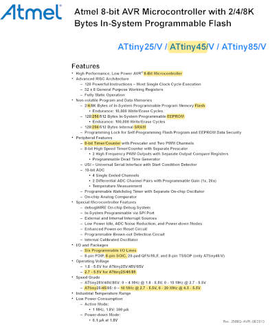
Summary Page (pg 1) :
First page is usually has a general description or provide a summary of the features available. Here also mentioned the version number "Rev. 8183F–AVR–06/12", which the vendor might update from time to time (but very rare).
I compared the features between ATTiny44A and the ATTiny45. There are only slight differences as seen from the summary sheet of both AVR chips; like number of I/O pins and speed.
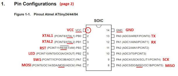
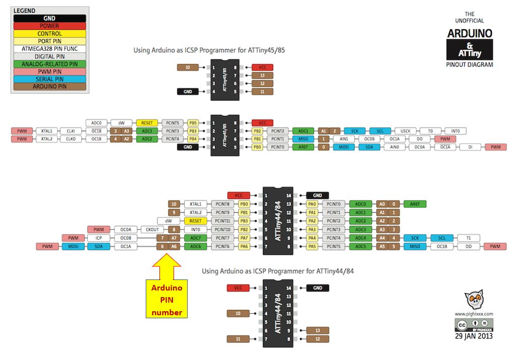
Pin Layout (pg 2 & 3) :
Page 2 shows the 'Pin Layout' diagram. There are 14 pins in total. But only 14 pins can be use by us for I/O.
My Hello World Connection Diagram :
I had printed out this Pin Layout diagram with my own markings in red color for reference, showing pin 5 (PB2) is connected to the LED, and pin 6 (PA7) is connected to the Switch.
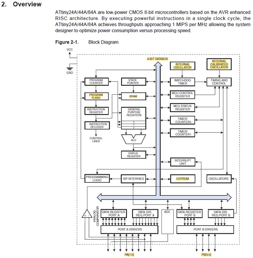
Architecture Overview (pg 8) :
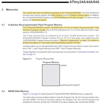
Memories (pg 15) :
Three type of memories are available in the ATTiny44A.
- Flash memory (also known as 'Program Memory Space')
for ISP Programming and which store the program
- SRAM memory (also known as 'Data Memory Space')
- EEPROM memory (a separate data memory space)
The datasheet provide information on operating condition example below :
Note : During periods of low VCC, the EEPROM data can be corrupted because the supply voltage is too low for the CPU and the EEPROM to operate properly. These issues are the same as for board level systems using EEPROM, and the same design solutions should be applied.
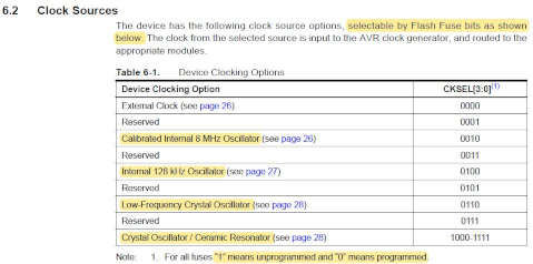
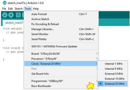
Clock System (pg 24) :
- Calibrated Internal 8 MHz Oscillator
AVR chip comes with its own internal oscilators as clock source. Total there are three of them. The default clock source for ATTIny44A with a longest start-up time and running an initial system clock prescaling of 8, (8 Mhz divided by 8) resulting in 1 MHz system clock.
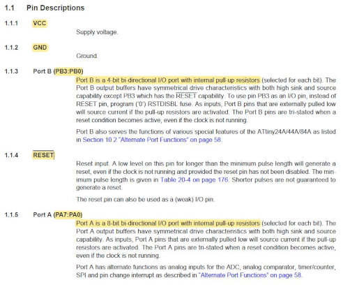
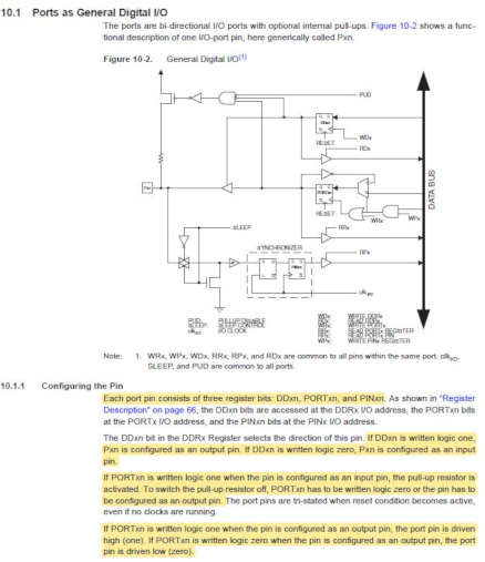
I/O Ports (pg 53) :
- switching Between Input and Output (pg 56)
- C Code Example (pg 57)
- Alternate Functions of Port A (PB0 to PA7 pins)
- Alternate Functions of Port B (PB0 to PB3 pins)
Pulse Width Modulator? (pg 68) :
- 8-bit Timer/Counter0 is a general purpose 8-bit Timer/Counter module, with two independent Output Compare Units, and with PWM support.??
- The 16-bit Timer/Counter unit allows accurate program execution timing (event management), wave generation, and signal timing measurement. (pg 85)
Timer/Counter Timing Diagrams (pg 101) :
Timer/Counter Prescaler (pg 113) :
- Prescaler Reset
- External Clock Source
Analog to Digital Converter (pg 132) :
Self-Programming the Flash (pg 152) :
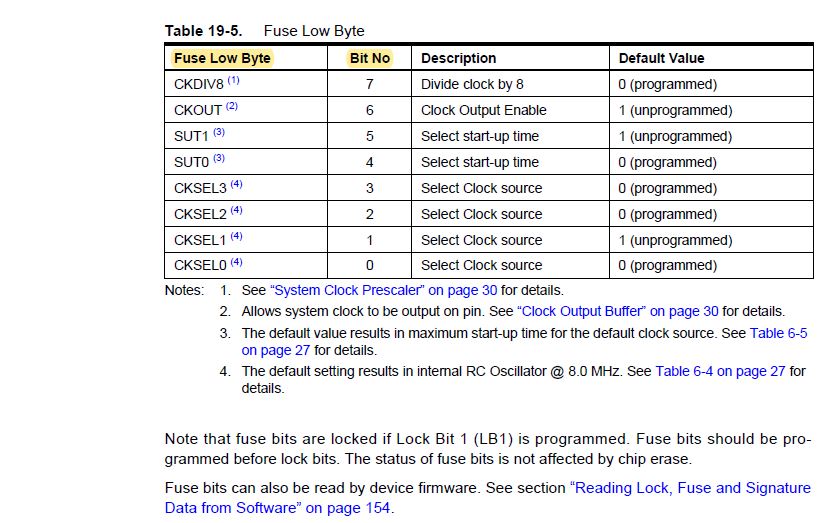
Reading Fuse Bits from Firmware (pg 154) :
- Fuse Low Byte (FLB)
- Fuse High Byte (FHB)
- Fuse Extended Byte (FEB)
Preventing Flash Corruption (pg 156) :
- During periods of low VCC, the Flash program can be corrupted because the supply voltage is too low for the CPU and the Flash to operate properly. These issues are the same as for board level systems using the Flash, and the same design solutions should be applied.
A Flash program corruption can be caused by two situations when the voltage is too low. First, a regular write sequence to the Flash requires a minimum voltage to operate correctly. Secondly, the CPU itself can execute instructions incorrectly, if the supply voltage for executing instructions is too low.
Lock Bit (pg 158) :
This section set the security to protect your program in the Flash memory.
Example : LB Mode 1 : No memory lock feature enable
Example : LB Mode 2 : Programing to Flash and EEPROM is disabled
Example : LB Mode 3 : Programing and verification to Flash and EEPROM is disabled
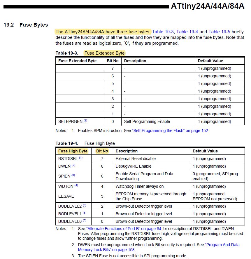
Fuse Bytes (pg 159) :
This portion state the three types of fuses and how to set these three fuses. The three Fuse bytes are called HIGH, LOW and EXTENDED.
We had used the 'Make Fuses' command in week 5 to burn the 'fuses' for our FabISP. This section provide the detailed information. Eg. H-Fuse: bit no.6: Enable Serial program downloading (SPI)
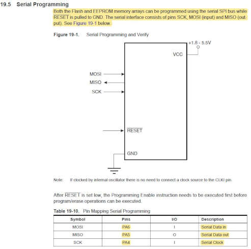
Serial Programming (pg 162) :
As in week 7, we can briefly touched on how to program our 'hello world' board. To program the AVR chip, we need to map to these six pins (VCC, GND, MOSI, MISO, RESET and SCK). We program the AVR chip by using the ISP 6-pin (2x3) cable.
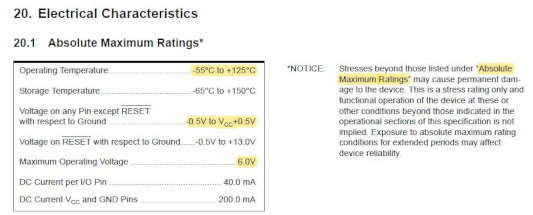
Electrical Characteristics (pg 172):
Here show the 'absolute maximum rating' that the AVR chip can withstand before being damaged.
Page 183 to 265 a whole bunch of charts?
These charts show the performance vs. various criterias...
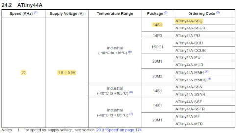
Ordering Information (pg 270) :
Under 'ordering information', you will find a list of every variation of the ATTiny44A. Our chip used is 'ATtiny24A-SSU', package code is 14S1
Packaging Information for 14S1 (pg 273) :
Here it show the physical dimenstion in mm and in inches.
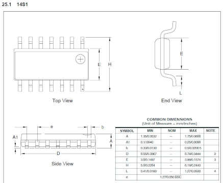
Table of Contents (pg 281 to 285)
~ End of datasheet ~
In order to program my hello world to do something, I need to write the code(program) for the AVR ATTiny44A microcontroller chip on the hello world board.
There are a few ways to do so.
Ways to programming AVR chip :
(1) AVR-GCC (Avrdude) toolchain :
(2) Arduino IDE (via a FabTinyISP Programmer)
(3) Atmel Studio 7 IDE
Hardware require :
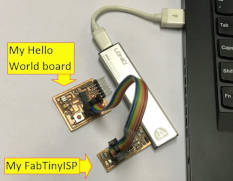
Programmer (ISP) : FabTinyISP
Target Board : Hello World board
Cable : ISP 6-pin (2x3) cable
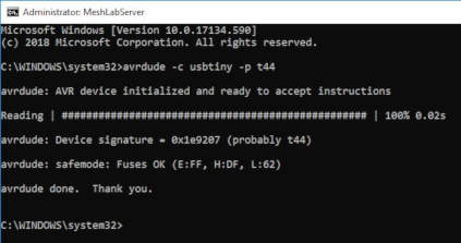
Pre-programming checking :
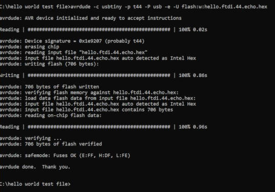
Always run "avrdude -c usbtiny -p t44" in the 'command line' to ensure 'avrdude' can detect both ISP (programmer) and target board. Example, if 'hello world' board is not detectable, you can immediate do some troubleshooting using a multimeter or check the programmer.
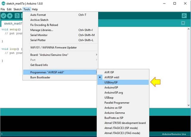
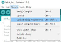
I deccided to start with Arduino IDE (Integrated Development Environment), which is the easier to learn for a beginner like me. However I am using a non-Arduino ISP, but my FabTinyISP as the programmer.
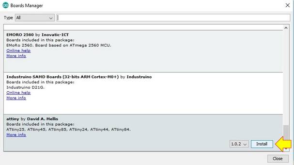
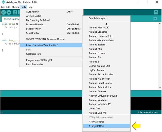
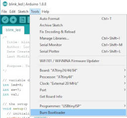
If you are using Arduino IDE to program your board, you need to burn the bootloader to the target board. You only need to do it one time, which is the first time you programming the board.
"The bootloader is basically a .hex file that runs when you turn on the board. It is very similar to the BIOS that runs on your PC. It does two things. First, it looks around to see if the computer is trying to program it. If it is, it grabs the program from the computer and uploads it into the ICs memory (in a specific location so as not to overwrite the bootloader). That is why when you try to upload code, the Arduino IDE resets the chip. This basically turns the IC off and back on again so the bootloader can start running again. If the computer isn't trying to upload code, it tells the chip to run the code that's already stored in memory. Once it locates and runs your program, the Arduino continuously loops through the program and does so as long as the board has power." ~ Sparkfun: Installing an Arduino Bootloader.
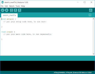
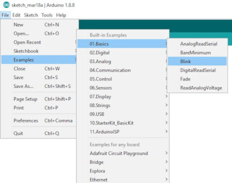
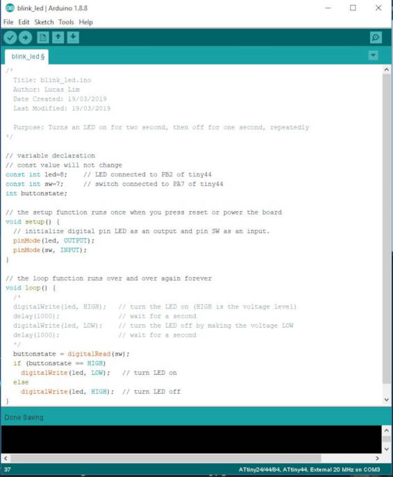
My code :
/*
  Title: blink_led.ino
  Author: Lucas Lim
  Date Created: 19/03/2019
  Last Modified: 19/03/2019

  Purpose: Press the switch button to turn on LED
*/

// variable declaration
// const value will not change
const int led = 8;    // LED connected to PB2 of tiny44
const int sw = 7;     // switch connected to PA7 of tiny44
int buttonstate;

// the setup function runs once when you press reset or power the board
void setup() {
  // initialize digital pin LED as an output and pin SW as an input.
  pinMode(led, OUTPUT);
  pinMode(sw, INPUT);
}

// the loop function runs over and over again forever
void loop() {
  /*
  digitalWrite(led, HIGH);   // turn the LED on (HIGH is the voltage level)
  delay(1000);               // wait for a second
  digitalWrite(led, LOW);    // turn the LED off by making the voltage LOW
  delay(1000);               // wait for a second
  */
  buttonstate = digitalRead(sw);
  if (buttonstate == HIGH)
    digitalWrite(led, LOW);   // turn LED on
  else
    digitalWrite(led, HIGH);  // turn LED off
}
Note :
File :
My program in Arduino code (blink_led.ino)
Programing in C in Arduino IDE
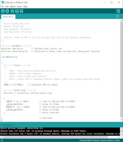
This is my first programming in C in the Arduino IDE. I took me one day of reading and searching for online tutorials to figure out AVR programming in C and how to configure the individual Pin(s), etc. I started out with working with one Pin to make the LED blink. Here I am using a comercial usbasp v2.0 programmer as my FabTinyISP is not working.
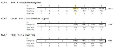
From the datasheet, you can set the bit to turn it on. The default is "0".
My Code in C - Pressing the switch button to turn on the LED :
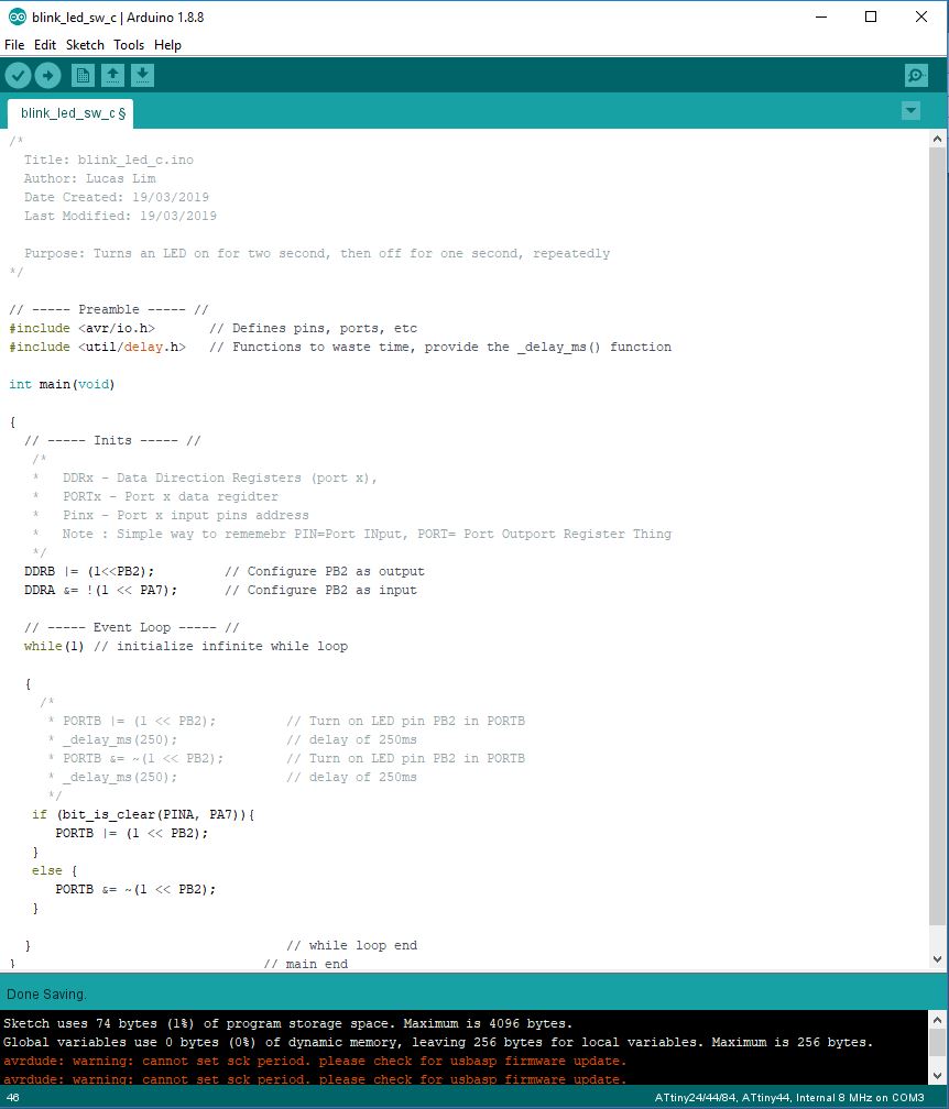
My code :
/*
  Title: blink_led_c.ino
  Author: Lucas Lim
  Date Created: 19/03/2019
  Last Modified: 19/03/2019

  Purpose: Press the switch button to turn on LED
*/

// ----- Preamble ----- //
#include < avr/io.h>       // Defines pins, ports, etc
#include < util/delay.h>   // Functions to waste time, provide the _delay_ms() function

int main(void)

{
  // ----- Inits ----- //
   /*
      DDRx - Data Direction Registers (port x),
      PORTx - Port x data register
      Pinx - Port x input pins address
      Note : Simple way to rememebr PIN=Port INput, PORT= Port Outport Register Thing

      Assignment operators
      To set a bit to one  |= (1 << PinNumber)
      To reset a bit to zero  &= ~(1 << PinNumber)
      To toggle a bit,  ^= (1 << PinNumber)
   */
  DDRB |= (1 << PB2);       // Configure PB2 as output.
  DDRA &= ~(1 << PA7);      // Configure PA7 as input.

  // ----- Event Loop ----- //
  while(1)                  // initialize infinite while loop

  {
    /*
      PORTB |= (1 << PB2);         // Turn on LED pin PB2 in PORTB
      _delay_ms(250);              // delay of 250ms
      PORTB &= ~(1 << PB2);        // Turn off LED pin PB2 in PORTB
      _delay_ms(250);              // delay of 250ms
     */
   // if (PINA & (1 << PA7)) {      // check bit 7 or "PA7" of PORTA is 0 or 1, true if 1, false if 0

   if (bit_is_clear(PINA, PA7)){
      PORTB |= (1 << PB2);          // Turn on LED pin PB2 in PORTB
   }
   else {
      PORTB &= ~(1 << PB2);         // Turn off LED pin PB2 in PORTB
   }

  }                                 // while loop end
}                                   // main end
Video of me pressing the switch button to light the LED :
File :
My program in C code (blink_led_sw_c.ino)
Finding :
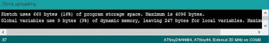
The file size of my program writen in Arduino is 660 bytes (16% of Program Space).
The file size of my program writen in C is 72 bytes (1% of Program Space).
Aurdino code tend to have high 'overhead' or excessive coding loaded into the Program Space.
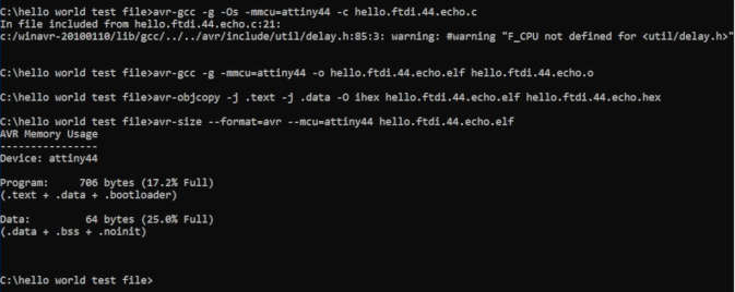
1. This is from week 7 - Electronic Design, which is possible to manually write C program in a C programming IDE, compile the c programming code into .hex file and manually uplading to Flash memory on the Hello World Board using the "avrdude".
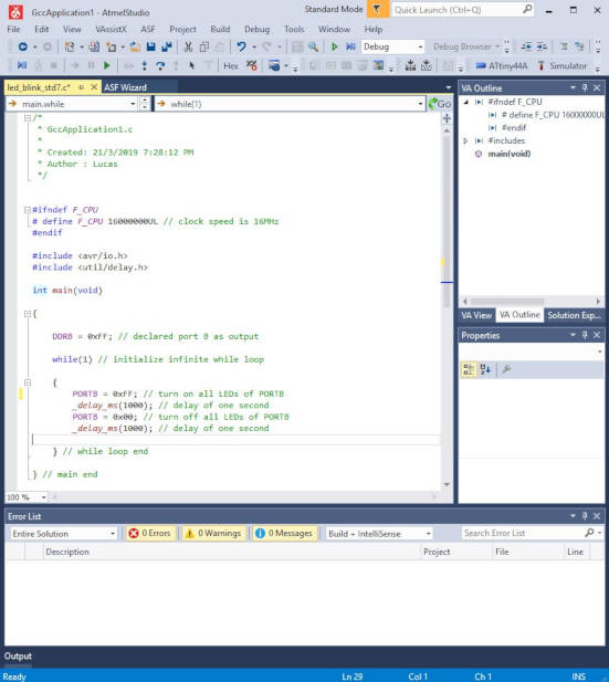
Atmel Studio 7 is a free IDE for writing C/C++ and debugging for all AVR microcontrollers with its integrated compiler.
1. Download the binary release (setup file) from Atmel Studio 7 website.
2. Open Atmel Studio 7
3. File -> New Project -> select 'GCC C Executable Project'
4. Write your C Code
5. To compile your code. Select 'Build' -> 'Build Solution'
I ran out of time, so did not complete trying out the Atmel Studio 7, but instead focus mainly on learning and just using the Arduino IDE for AVR programming. Atmel Studio 7 has a user-friendly editor, and had a built-in 'simulator' but I have yet to try it out.
Reference :
Atmel Studio 7 website.
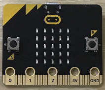
I had borrowed this "BBC micro:bit" board from my instructor, Mr Steven, to test it out over the weekend.
"The BBC micro:bit is a handheld, programmable micro-computer that can be used for all sorts of cool creations, from robots to musical instruments – the possibilities are endless" ~ microbit:website
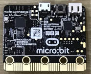
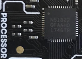
The microcontroller for the micro:bit is a "Nordic nRF51822 (QFAA model)" by Nordic Semiconductor, measure 6mm x 6mm. It is built around the 32-bit ARM® Cortex™-M0 CPU with 256 KB flash and 32 KB RAM.
Some of the features of this chip are as follow :
| Microcontroller : | 32-bit ARM Cortex M0 |
| Program Memory : | 256kB Flash |
| Ram : | 32 kB |
| Oscillators : |
- Low power 16MHz crystal and RC oscillators - Ultra low power 32kHz crystal and RC oscillators |
| Pins : | 31 GPIO (General Purpose Input/Output) |
|
Built-in radio : |
Bluetooth 4.2 (Multiprotocol 2.4GHz radio) |
|
On-air data rate : |
250 kbps, 1 Mbps or 2 Mbps |
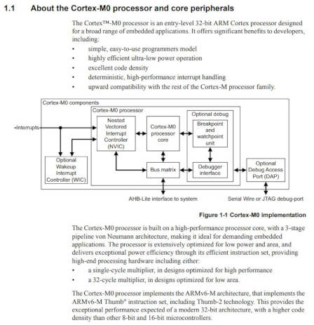
The ARM Cortex-M family are ARM microprocessor cores which are designed for use in microcontrollers. ~ Wikipedia: ARM Cortex-M
The Nordic nRF51822 microcontroller chip contain the ARM Cortex-M0 32-bit processor.
The Cortex-M0 processor implements the ARMv6-M architecture. Cortex-M0 processor is meant for general use. Unlike the 'ARM11' which is specically meant for smartphone. The Cortex-M0 processor is fully programmable in C and no need to write assembly code.
Inside the Cortex-M0 processor, contain one 'processor' core integrated with other components (like I/O controllers, memory, etc) in the same chip. In other ARM Family, there might contains one or more processor cores. When it is said that the Cortex-M0 processor implements the ARMv6-M architecture, it simply meant that it implement the set of standard as well as optional features as defined in the ARMv6-M architecture.
The ARM Cortex-M0 processor is similar to the AVR microcontroller, it has Flash momory space for program, SRAM momery space for data. In addition, it has its own built-in Flash Programmer.
References :
- Cortex™-M0 Devices : Generic User Guide on infocenter.arm.com
ARM (generic) Archirecture from Wikipedia :
I had searched online for ARM Cortex-M0 datasheet as well as ARMv6-M architecture, but not able to get any official documentation. On ARM website, it require you to register for a 'Developer' account in order to obtain access to the confidential documentation. I decided not to do so, as I am not familiar with this, and I do not want to waste too much of my time. So I referred to a generic ARM Archecture from Wikipedia.

References :
- Wikipedia: ARM architecture
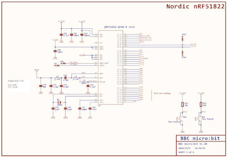
From a beginner point of view and the lack of the actual datasheet for the ARM Cortex M0 MCU, in term of hardware, there are similarity, there the central processor unit, three type of memory, it has Flash memory for uploading of the program, SRAM and the EBI might be similar to EEPROM.
However the three type of memories are neatly arrange side-by-side and supervised by a 'memory controller'. Example the memory controller fetches the program from Falsh and send the data over the databus to the processor and other parts of the circuit. The ARM MCU offer a wide range of features whereby each seperate vendor/manufacturer can choose to implement them or not. Like bluetooth radio, ethernet feature, etc.
The PIOs (pins) are indicated. The primary ones are all with the same configuration. The other PIOs are dependant on what features are implemented...
The Nordic nRF51822 microcontroller chip can be program using 'Microsoft MakeCode Editor' or 'micro:bit Online Python Editor'.
micro:bit Online Python Editor runs a version of Python called MicroPython that’s designed to run on small computers like the micro:bit. It’s a full implementation of Python 3 so when you move onto other things (such as programming Python on a Raspberry Pi) you’ll use exactly the same language. ~ micro:bit microphyton docs.
I am using Microsoft 'MakeCode Editor' as it is easier to learn and fast to program the micro:bit using blocks and JavaScript.
1. Plug in micro:bit board using the usb cable provided in the box. The LED status light will lit up and computer will detect the new USB device.
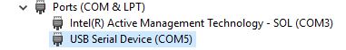
micro:bit usb device detected on the computer as a usb drive
2. Go to Microsoft 'MakeCode Editor' website
https://makecode.microbit.org/
3. Click on "New Project"
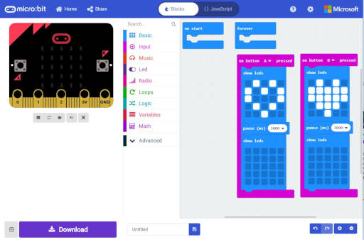
4. The MakeCoke User Interface appear.
On the right side is a simulator to test-run your program
On the centre column is a list of 'blocks' which you can drag to the right
On the right column is the 'workspace' where you build your main program
By default, there will be two 'blocks' in the 'workspace', namely
- the 'on start' which will run the code when the board is power-up, and
- the 'forever' block which will run any code placed here in a loop in the background.
5. At the centre column -> Click on the 'Basic' tab -> Drag the 'on button pressed' block into the workspace. This will run code when the button is pressed. By default, 'Button A' is selected for you, you can change to button B if you like.
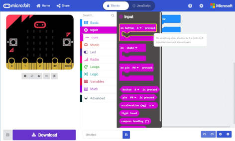
Dragging the block that involve "Button A" to the right
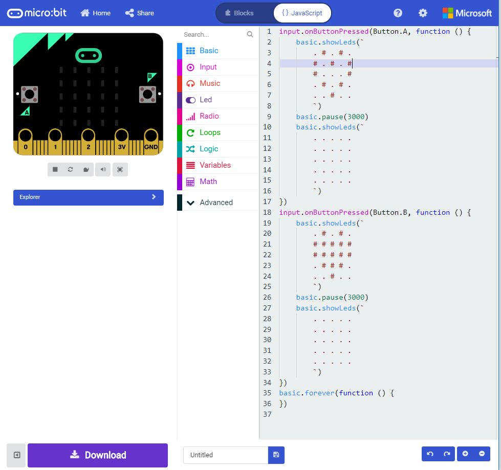
6. Next place a 'show leds' block inside the 'on button pressed block' and draw an outline of a heart shape. This will display the heart shape when button A is pressed. Then add a 'pause' as well as an empty 'show led' block' below the it.
7. I created a simple program that has the following function :
- When 'Button A' is press, it will display heart (outline) for 3 seconds (which is 3000 miliseconds) and then a blank screen
- When 'Button B' is press, it will display heart (outline) for 3 seconds (which is 3000 miliseconds) and then a blank screen
8. Click the 'Download' button on the bottom left of the editor screen. Specify the location to save the '.hex' file.
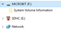
9. Once the hex file has downloaded, copy it to your micro:bit just like copying a file to a USB drive. On Windows you can right click and choose "Send To→MICROBIT."
7. Locate the .hex file and drag to the micro:bit drive (mine is drive F). Alternatively, you can right click on the .hex file and choose "Send To→MICROBIT.
8. The led light on the front of the micro:bit will blink as the program is been transfered. Once the program finished downloading, it will run the program automatically.
Click on 'Javascript' button at the top to go into Javascript editor mode :
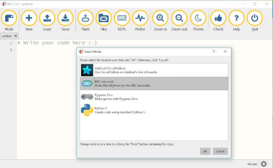
1. Download Mu ver 1.0.2 from Mu website @ https://codewith.mu/
2. Lauch Mu (Python editor)
3. Click on the "Mode" button and select "micro:bit"
4. Follow the tutorial on this online ebook on microbit micro python
5. In the editor, on line 1 type "from microbit import *" and this will import all the libraries needed for micro:bit
6. I writen the following code
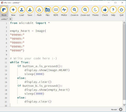
7. Click on the "Flash" button and Mu will automatically transfer the .hex file onto the micro:bit board
8. Press button A and B to try it our. It worked exactly as the program created earlier using 'Microsoft MakeCode Editor'
References :
- micro:bit website
I was a bit overwhelmed by all the information this week. In addition, when I start to program my 'hello world' board, my FabTinyISP was not working properly, and had to borrow a programmer from my instructor.
However in the end, after seeing the LED blinking on my 'hello world' board, followed by making my switch to control the LED, I felt a great sense of joy and accomplishment. I am able to write program to the AVR chip. It is an remarkable achievement.
Exprience on Datahsheet :
You have to know what you're looking for, then refer to the datasheet for the answer or reference.
Exprience on Programming :
You need to know the fundamental of programming. The fundamental of programming is like a flowchart diagram, consists of sequence of actions like "do this, then do that..." or logic (decision) "if this is true, then do that, or else do that...". Then it be easier to program in any programming language like the Arduino code, C programming or Phyton.
My AVR Programming toolchain :
I would choose to use the Arduino IDE to write my code. Reason is because it is user friendly and so complicated/overwheming. The Arduino board is running on Atmel AVR chips, the IDE is actually using "avrdude" to transfer the program to the target board. However, I plan to write in C programming code, then in Arduino code as the file size is much smaller.
Exprience on hardware programmer :
It is advised that you keep a backup ISP programmer as a spare. My FabTinyISP is not working this week. I plan to convert my Arduino Uno board into a programmer or use a commerical programmer for the time being. Until I have a chance to fabricate anothe FabISP in the Fab Lab.
- Elliot Williams, 2014, Make : AVR Programming, Maker Media, Inc. CA, USA. ISBN: 978-1-449-35578-4
- Understanding Embedded Systems - the basics (by electronics-notes.com)
- Arduino website
- Sparkfun: Installing an Arduino Bootloader, using packet AVR Programer, using Arduino as an ISP
- AVR. How to configure as output just one pin?
- C - Operators