
Fab Academy 2019 - Lucas Lim
12. Output Devices
12. Output Devices
Group assignment:
For this week 'Output Devices' assignment, I am working toward my final project. Initially was planning to use a 7-segment LED display modules but eventually decided to use a LCD display module with a I2C adaptor which only require 4 pins.
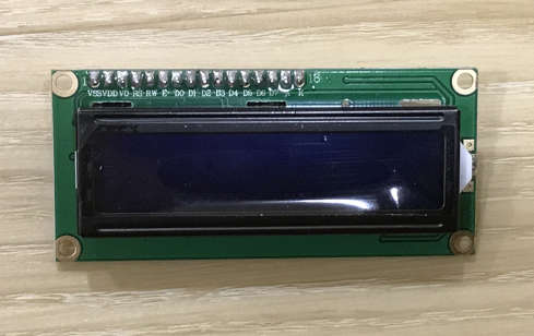
The LCD Display Module (1602A) is one of the popular LCD display in the market which is able to display 16 x 2 (16 columns 2 lines) which is up to 32 characters.
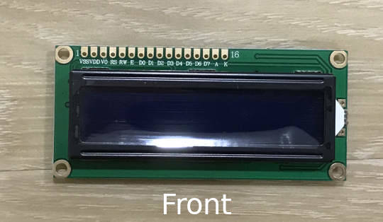
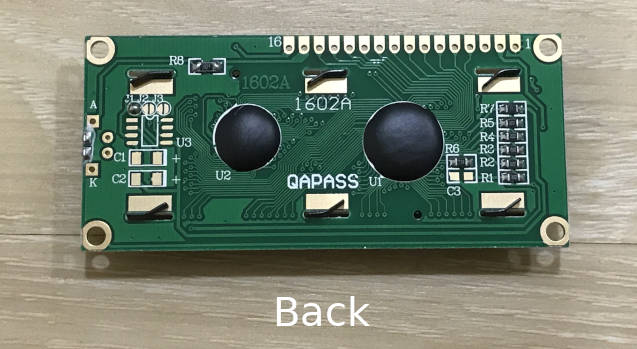
LCD Display module front and back :
References :
- LCD Display Module 1206A (1602A) Datasheet 1
- LCD Display Module 1206A (1602A) Datasheet 2
The LCD Display Module (1206A) by itself will require a total of 16 pins. With a I2C interface module (or sometimes refer to as a 'I2C backpack' or 'I2C adaptor'), it's helps to reduce the number of pins required down to 4.
I2C definition :
I2C allows one or more 'master' devices to talk to one or more 'slave' devices (like sensors, another MCU, LCD display, etc) over two wires. I2C support up to 127 devices. The two wire are refer to as 'data line' and 'clock line', connected to SDA (also refer to as serial data) and SCL (serial clock) pins. The data transmitted sort-of piggy-bag on each other.
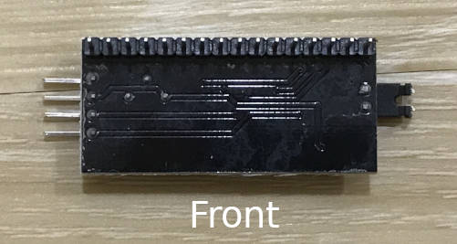
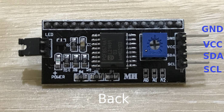
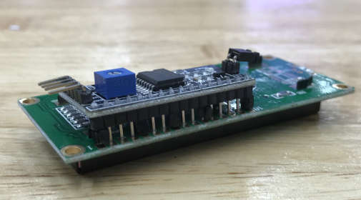
The I2C interface shown below is compatitible with my LCD display module (1206A), that attachs to the LCD display module. It only has 4-pins (2 for data connections, 1 for VCC and 1 for GND)
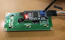
I2C interface front and back :
References :
- I2C interface for LCD Datasheet 1
- I2C 1602 Serial LCD Module Datasheet 2
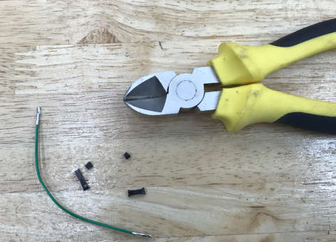
As the 16 pins on the I2C adaptor were too long, I used a short jumper cable and removed its headers at both ends and cut out into short pieces of equal length. This pieces will act as cushion for my I2C adaptor and the LCD display, to provide a distance (or gap) between both electronic boards.
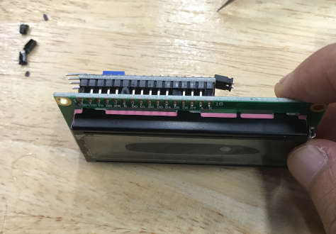
Then I soldered the I2C adaptor and the LCD display module together and used . My completed LCD display module (with the I2C interface)
1) I followed this simple online guide to connect the I2C LCD Display module to my Arduino Uno.
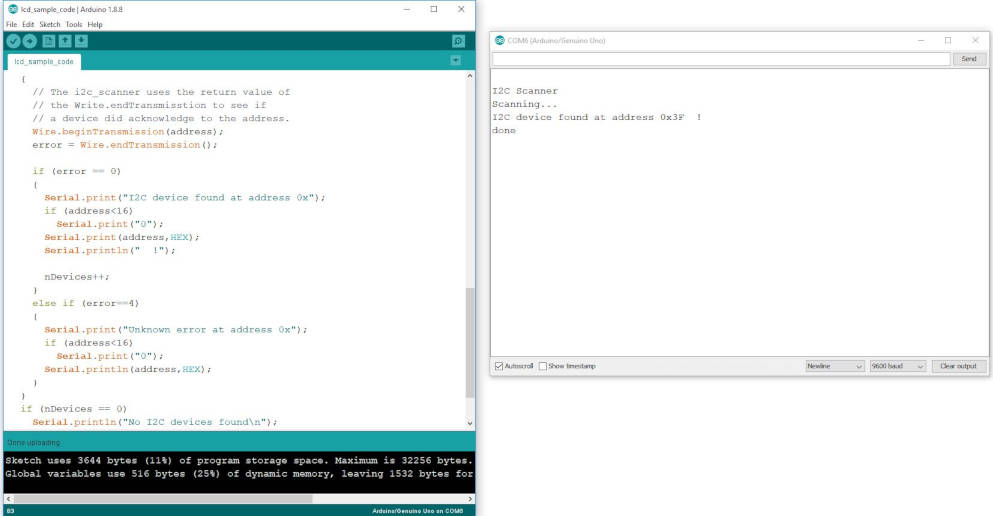
2) Then I followed this guide and run the 'I2C Scanner' sketch to find the I2C address of my I2C interface. My LCD I2C address is '0x3F'.
https://playground.arduino.cc/Main/I2cScanner/
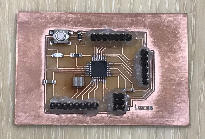
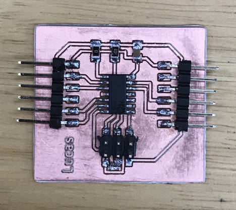
I had made my very first Arduino-compatible board.
More details are provided at 'My Final Project Electronics Design and Fabrication' page.
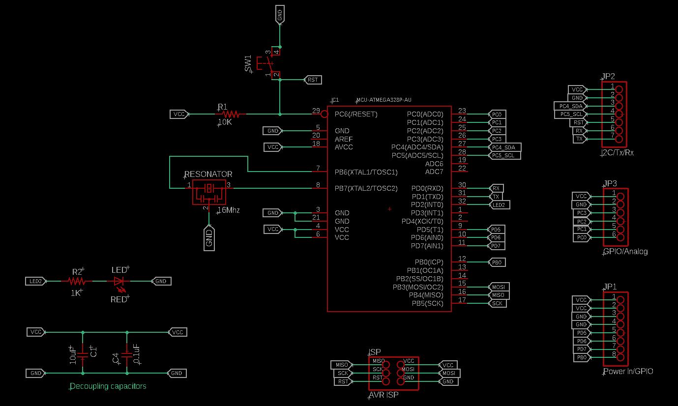
Schematics :
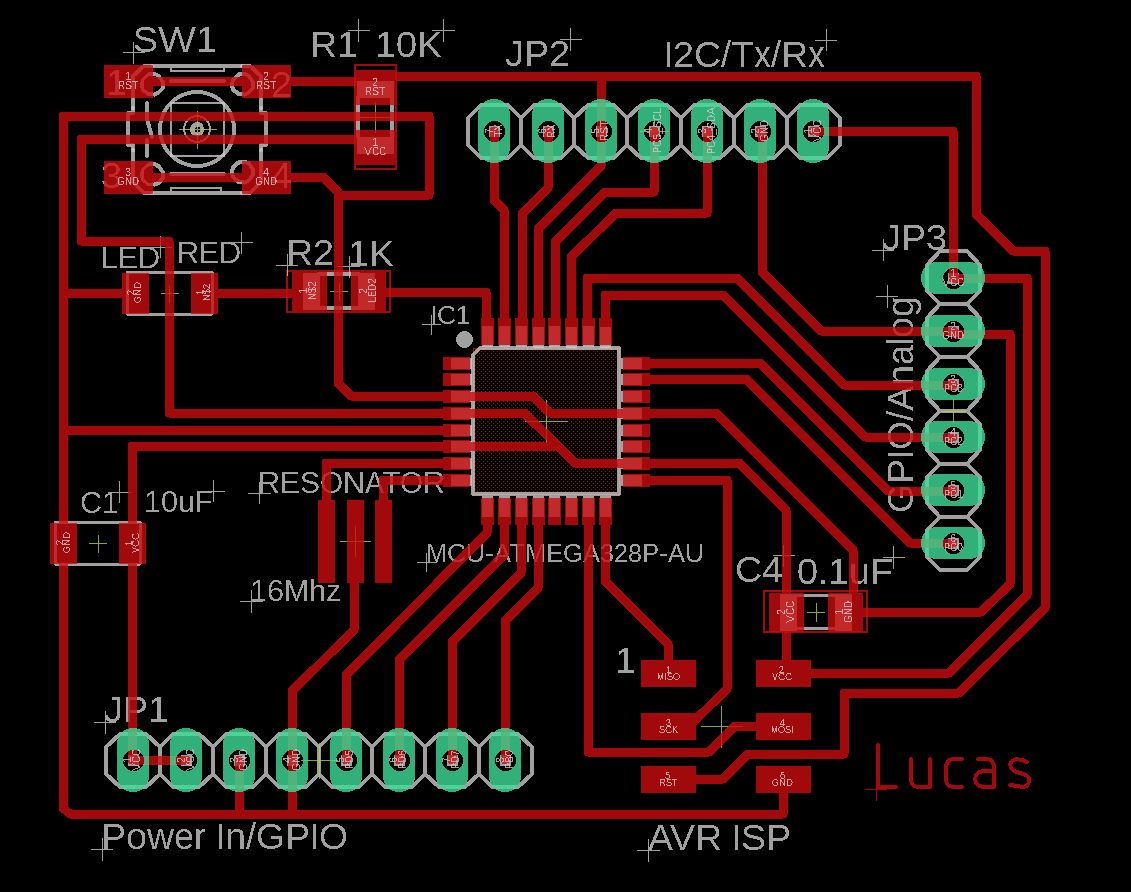
Board design :
My completed board :
/*
Title: lcd_i2c_lucas
Author: Lucas Lim
Date Created: 8/4/2019
Last Modified: 9/4/2019
Purpose: To display text to LCD display module with I2C adaptor.
Dispalying first text message and wait for 3 seconds before
displaying second message at pre-defeined position
*/
#include < Wire.h>
#include < LiquidCrystal_I2C.h>
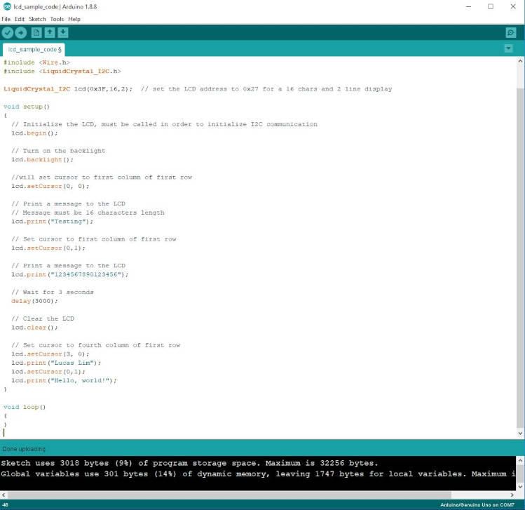
LiquidCrystal_I2C lcd(0x3F, 16, 2); // set the LCD address, for a 16 chars and 2 line display
void setup()
{
Wire.begin();
// Initialize the LCD, must be called in order to initialize I2C communication
lcd.begin();
// Turn on the backlight
lcd.backlight();
}
void loop()
{
// Wait for 3 seconds
delay(3000);
//will set cursor to first column of first row
lcd.setCursor(0, 0);
// Print a message to the LCD
// Message must be 16 characters length
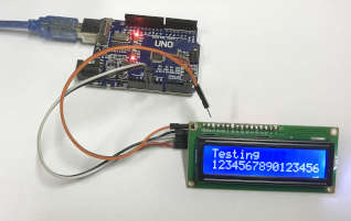
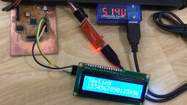
lcd.print("Testing");
// Set cursor to first column of first row
lcd.setCursor(0,1);
// Print a message to the LCD
lcd.print("1234567890123456");
// Wait for 3 seconds
delay(3000);
// Clear the LCD
lcd.clear();
// Set cursor to fourth column of first row
lcd.setCursor(3, 0);
lcd.print("Lucas Lim");
lcd.setCursor(0,1);
lcd.print("Hello, world!");
// Wait for 3 seconds
delay(3000);
// Clear the LCD
lcd.clear();
}
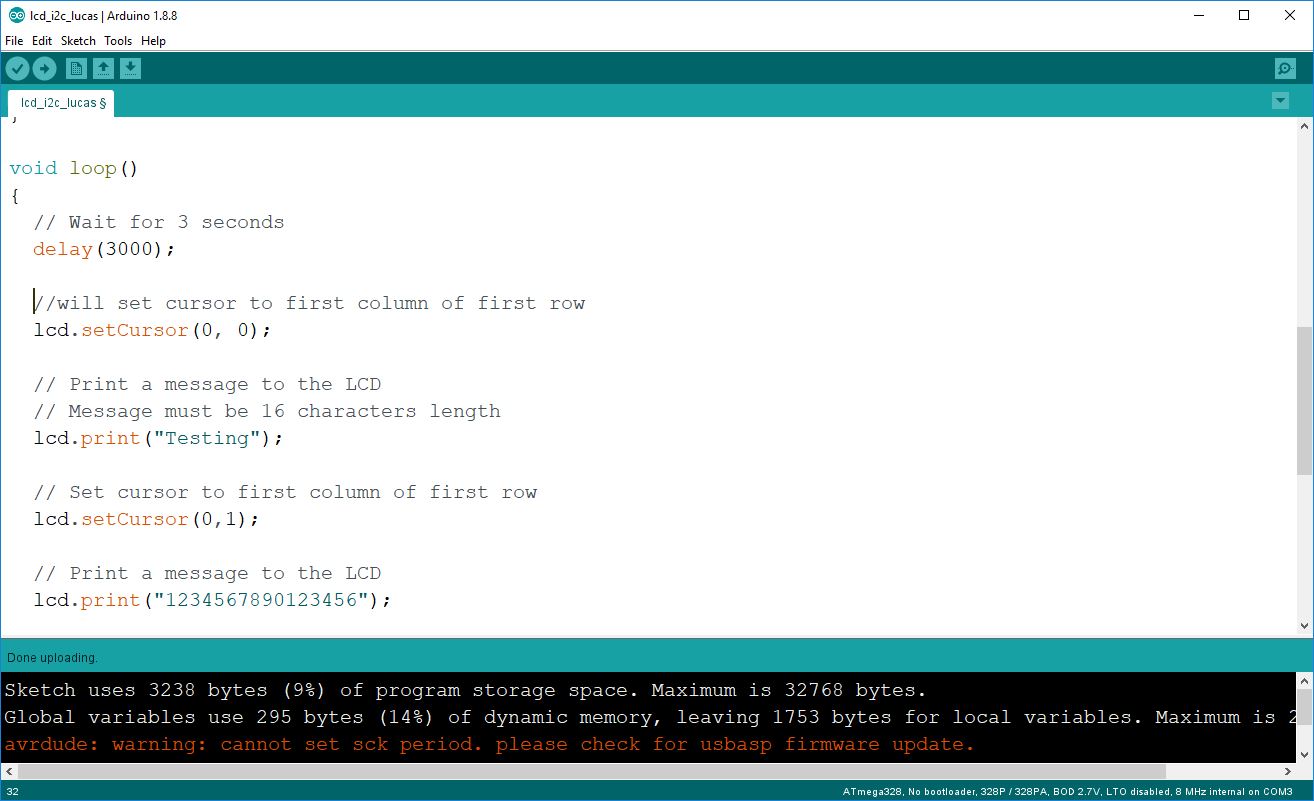
Programming my board :
Result :
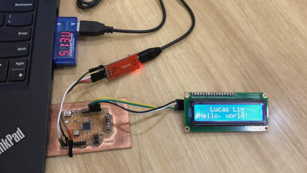
I am using a portable and small LED usb multimeter known as the 'Charger Doctor'. The range is 3.5V - 7.0V, 0A - 3A.
The cuurent draw is 0.5A or 500mA, which is the common power output of a USB 2.0 standard.
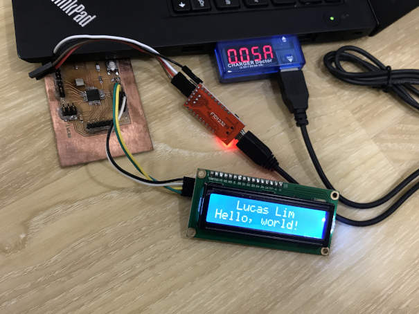
The voltage is 5.14V.
This week major challenge was that I was trying to use back the board that I made for the input device and integrate with the I2C LCD display, but faced some issues.
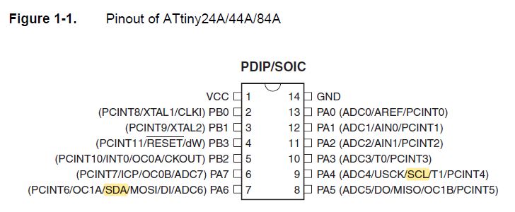
I downloaded the TinyWireM as well as the LiquidCrystal_I2C libraries, but kept encountering some errors with some variables/lines. Later than I found out that I had to edit the LiquidCystal.h and LiquidCystal.cpp files to manually add in "(__ATtiny44__)" text, only then I can program my board. I connected the SDA And SCL pins. But it still not working... Beside I2C is very new to me and my board SDA and SCL pins are used for the ISP, I should have pulled out these pins to the side...
- My schematic design (atmega328p_Lucas.sch)
- My board design (atmega328p_Lucas.brd)
- My code for the LCD display (output device) :
lcd_i2c_lucas.ino
- I2C for LCD 16×2 Module Usage Guide
-
I2C Scanner for Arduino
- Basics of I2C with AVR
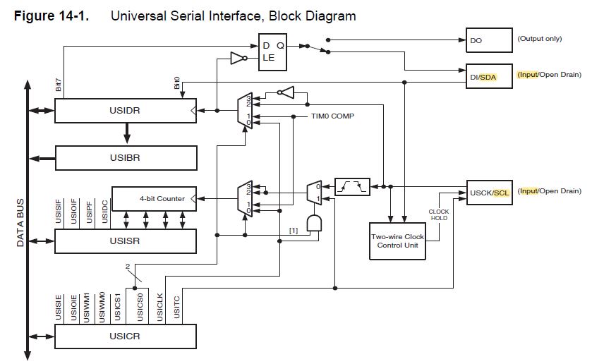
- ATTiny USI I2C Introduction
- Youtube : How I2C Communication Works and How To Use It with Arduino
- website
- website