
Fab Academy 2019 - Lucas Lim
11. Input Devices
11. Input Devices
Group assignment:
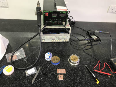
Main goal for this week is to design and fabricate a microcontroller board with an input device/sensor, capturing the data with the input device and reading it. In addition, using an oscilloscope to perform some measure of the signal.
A sensor is simply defined as a device that is able to interact or senses changes in the external physical environment (temperature, motion sensor, etc) and capture reading from it.
Learning for this week :
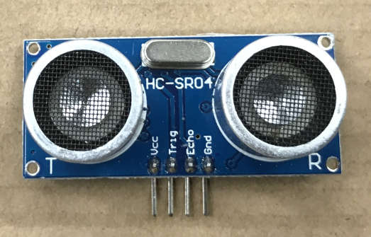
I choose the HC-SR04 Ultrasonic Sonar Distance Sensor as my input sensor module out of the many sensors that was in the Arduino development kit. This is the first time I am using an input sensor.
The HC-SR04 ultrasonic sonar distance sensor is able to measure distance from about 2cm to 400cm away (max range up to 3m, 10cm to 250cm for best result).
The first step is to look at the datasheet of the Ultrasonic Sonar Distance Sensor.
After some searching for the datasheets online, the datasheets available online are quite brief or lack much details about its internal working. However there are many online user guides written by other people on the use of this sensor.
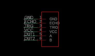
| Pin Name | Pin Description |
|---|---|
| VCC | 5V power supply |
| Trig | Trigger Input Pin |
| Echo | Receiver Output Pin |
| Gnd | Power ground (0V) |
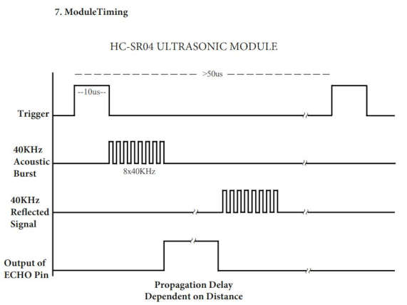
From the datasheet :
1) A short pulse of at least 10μs (HIGH level signal) is supplied to the trigger input to start the ranging.
2) The sensor convert electrical signal to ultrasound. It emits an ultrasound at 40kHz (eight cycles of sonic bursts at 40 kHz) through the air via its two 'eye-like' shaped transmitter/receiver.
3) If the ultrasound hit an object along it path, the ultrasound will bounch back to the sensor, through HIGH level. The ECHO pin will goes HIGH for a period of time from the sending ultrasonic (uS) wave to returning. Another way of explanation, is ECHO Output pulse to microcontroller, width is the time from last of 8 40KHz bursts to detected reflected signal (microcontroller Timer gate signal)
4) The distance of an object can be calculated through the time interval between sending trigger signal and receiving echo signal. Therefore formal is as follow :
is as follow :
Test distance = (high level time × velocity of sound (340M/S) / 2, or
uS / 58 = centimeters or
uS / 148 = inch
Note: us equal μs (microsecond), a ASCII character u is used to indicate micro in place of μ
References :
- HC-SR04 Datasheet
- https://www.mpja.com website : HC-SR04 User Guide
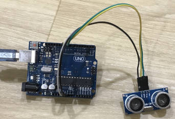
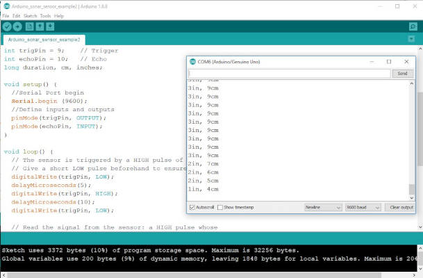
The next step is to test my sensor to see if it is working properly. I tested on a 'working reference board' (which is my Arduino UNO board) to understand how the sensor work, what the input require and output generated, as well as the accuracy of the output. I followed a sample Arduino code online to test it out.
References :
- Complete Guide for Ultrasonic Sensor HC-SR04 with Arduino
I made reference to Neil's board design. and attempted to replace the ATTiny45 chip with ATTiny44A, as it offered more PINs. So I drew a new board design. I hoping this board with more pins can also be used for next week Output Devices assignment and my Final Project.
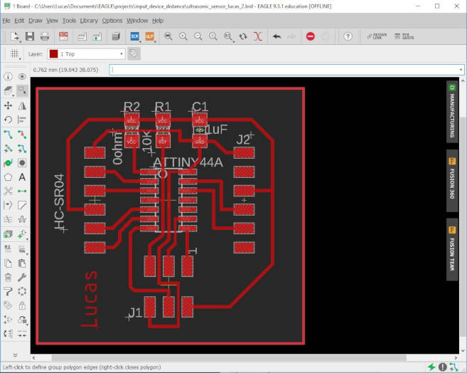
At first, it was hard to 'wiring up' the components in EAGLE board design editor. I tried a few times, going to-and-fro between the schematic and board design to make changes. Later on, I resorted to making reference to my 'hello world' design and finally was able to design my 'Hello HC-SR04' board.
Neils' 'Hello HC-SR04' board : The pin connections on ATTiny45
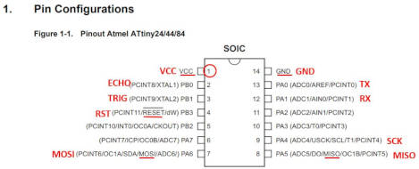
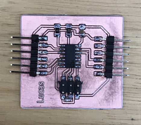
My 'Hello HC-SR04' board : The pin connections on my ATTiny44A
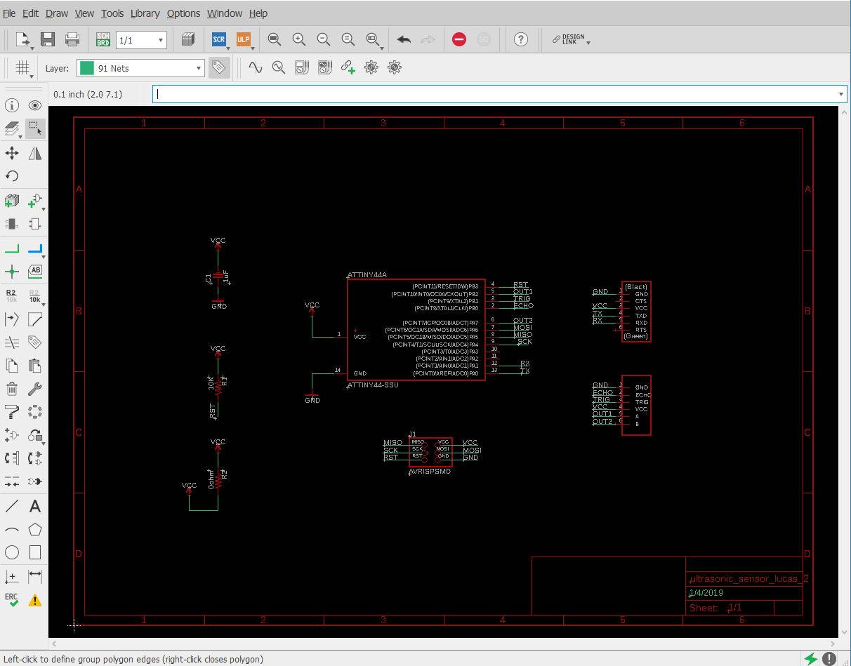
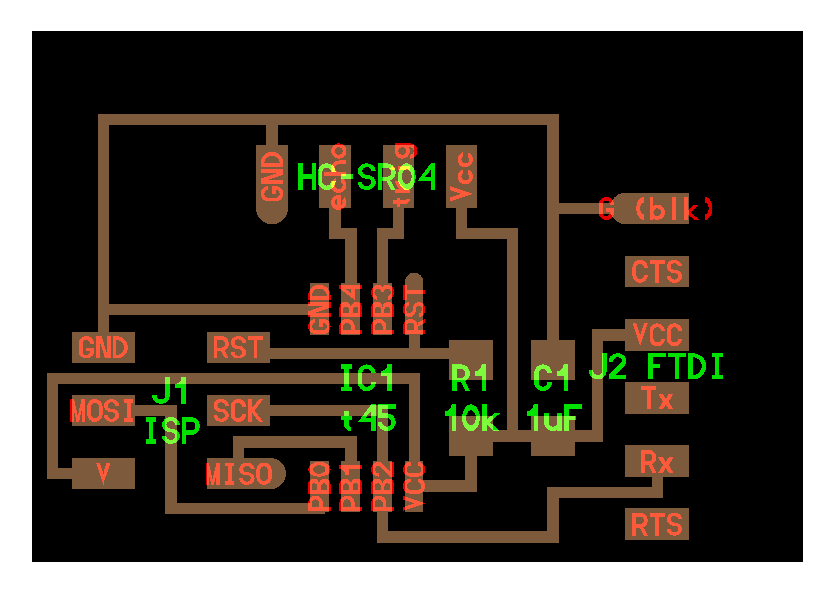
3) My Schematic design
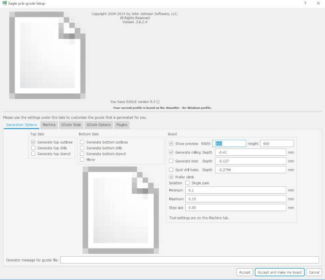
Placing a small 1uf Capacitor after VCC and before resistor and the microcontroller to act as a filter. A 10 Ohm pull-up resistor. A 0 Ohm resistor just for running a trace underneath.
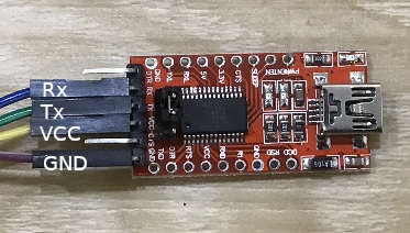
I referred to this online guide for Ultrasonic Sensor HC-SR04. The original code is meant for Arduino Uno board, however I modified to apply the code to my self-designed 'Hello HC-SR04' board. I modified the Pins, changed the formulas for calculating the 'cm' and 'inches' by following the datasheet formula, and have my board sending the output data to the computer over the FTDI Pins.
References :
- Complete Guide for Ultrasonic Sensor HC-SR04 with Arduino
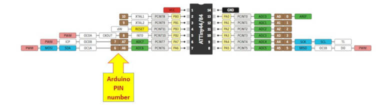
I mapped ATTiny44 'Echo' and 'Trigger' pins with Arduino PIN number by referring to the 'Arduino and ATTiny Pin Layout Diagam' posted on
www.electrodragon.com website..
My code :
/*
  Title: Ultrasonic_sensor.ino
  Author: Lucas Lim
  Date Created: 2/4/2019
  Last Modified: 4/4/2019
  Purpose: To activate Ultrasonic sensor and send data to computer

  Ultrasonic sensor Pins:
     VCC: +5V DC
     Trig : Trigger (INPUT) - Arduino Pin9 (PB1)
     Echo: Echo (OUTPUT) - Arduino Pin10 (PB0)
     GND: GND

  Original code created by Rui Santos, https://randomnerdtutorials.com
 */

#include < SoftwareSerial.h>
SoftwareSerial mySerial(1, 0); // RX, TX


int trigPin = 9;    // Trigger
int echoPin = 10;   // Echo
long duration, cm, inches;

void setup() {
  //Serial Port begin
  mySerial.begin (9600);
  //Define inputs and outputs
  pinMode(trigPin, OUTPUT);
  pinMode(echoPin, INPUT);
}

void loop() {
  // The sensor is triggered by a HIGH pulse of 10 or more microseconds.
  // Give a short LOW pulse beforehand to ensure a clean HIGH pulse:
  digitalWrite(trigPin, LOW);
  delayMicroseconds(5);
  digitalWrite(trigPin, HIGH);
  delayMicroseconds(10);
  digitalWrite(trigPin, LOW);

  // Read the signal from the sensor: a HIGH pulse whose
  // duration is the time (in microseconds) from the sending
  // of the ping to the reception of its echo off of an object.
  pinMode(echoPin, INPUT);
  duration = pulseIn(echoPin, HIGH);

  // Convert the time into a distance
  cm = duration/58;         // uS divide by 58 to give cm
  inches = duration/148;    // uS divide by 148 to give inches

  mySerial.print(inches);
  mySerial.print("in, ");
  mySerial.print(cm);
  mySerial.print("cm");
  mySerial.println();

  delay(250);
}
Note :
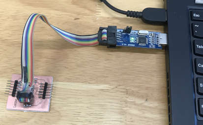
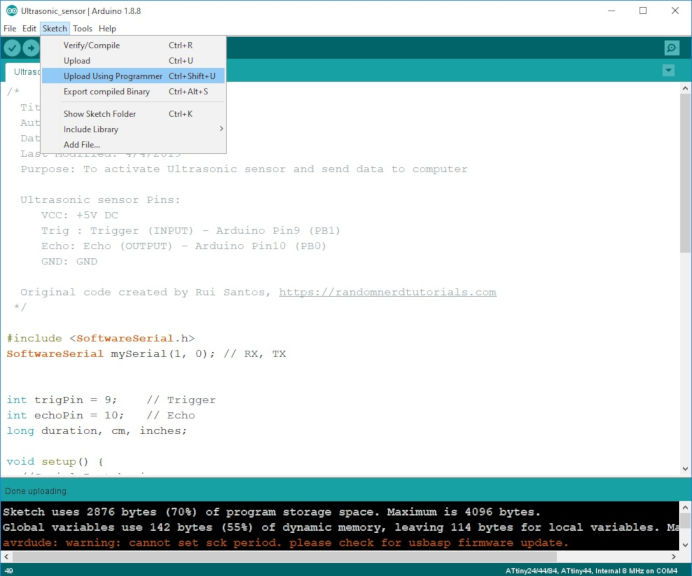
I compiled and uploaded my code using Arduino IDE using a commercial USBAsp ver 2.0.
I am new to Python and here are the steps to install Python and pySerial.
1) Download Python 3.7.3 64-bit from Python website. During install, tick the box "Add Python 3.7 to PATH"
2) Open Windows command prompt in Administrator Mode and run the command "pip install pyserial". The pySerial package is an add-on and allow Python to import the 'serial' library.
3) Open Python IDLE
4) Add in "import serial" into your code to import the 'serial' library.
I am new to Python programming and after hearing Python mentioned a couple of time during lesson, therefore I would like to explore on it. In the future, I hope to be like Neil to create UI (User interface) using python.
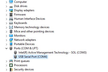
My FTDI connector is detected as 'COM4' port.
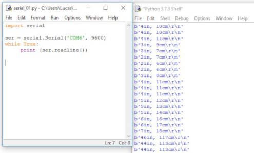
My simple Python code to read in the data from the ultrasonic input device :
#
# Title: Ultrasonic_sensor.py
# Author: Lucas Lim
# Date Created: 2/4/2019
# Last Modified: 4/4/2019
# Purpose: To read data from Ultrasonic Sensor board
#
#import serial library
import serial
#open serial port
ser = serial.Serial('COM4', 9600)
# displayed serial port info
print (ser)
# displayed data read from from COM port
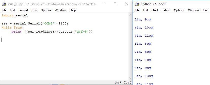
while True:
print ((ser.readline()).decode('utf-8'))
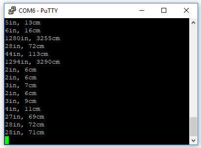
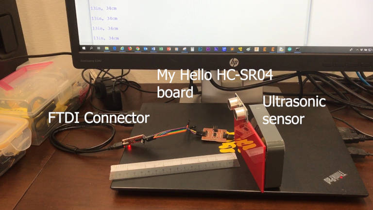
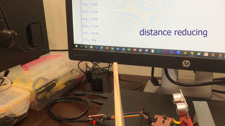
My 'Hello HC-SR04' board is working ok, it is sending data over the FTDI cable and connector. My Python code is working ok too in picking up the data from serial port 'COM4' and displaying the data in a reading format.
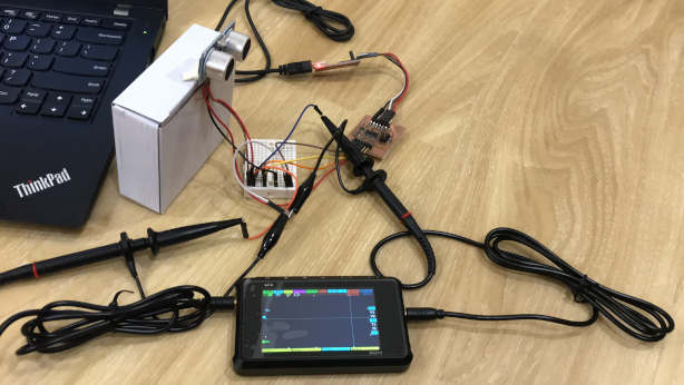
Setup :
I am using a pocket-sized 'DS213 MINI DSO' 4-Channel digital oscilloscope. Channel A (on the left) to measure the input pulse (TRIG) and Channel D (on the right) to measure the returning pulse (ECHO)(if any).
I used small breadboard and branch out some jumber cable so that my digital oscilloscope is able to properly connected and probe the TRIG, ECHO and connected to the common GND.
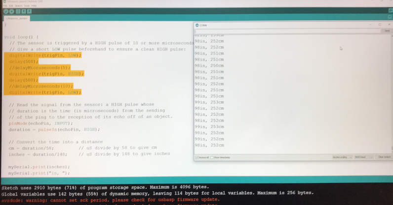
My revised code :
Set delay of 500 milliseconds for TRIG so that I can be able to easily view the square wave.
void loop() {
  // The sensor is triggered by a HIGH pulse of 10 or more microseconds.
  // Give a short LOW pulse beforehand to ensure a clean HIGH pulse:
  digitalWrite(trigPin, LOW);
  delay(500);
  //delayMicroseconds(5);
  digitalWrite(trigPin, HIGH);
  delay(500);
  //delayMicroseconds(10);
  digitalWrite(trigPin, LOW);
...
  //delay(250);
}
What to measure?
1) The TRIG pin on my board will turn HIGH (for 500ms).
2) This activates the HC-SR04 Ultrasonic Sonar sensor. To activate, the sensor must receive a HIGH pulse of at least 10us or more. The sensor transmit out 8 cycle of ultrasonic burst at 40kHz and wait for the reflected ultrasonic burst.
3) After which the TRIG pin will turn LOW (silence) for 500ms. This slow down the sensor and it is for easy reading.
4) When the sensor detected the reflected ultrasonic wave, it will set the ECHO pin to HIGH (5V) and delay for a period (width) which proportion to distance.
5) The ECHO pin on my board will receive a pulse (input signal) from the HC-SR04 Sensor. This allows my microcontroller to calculate the distance of the object from the sensor.
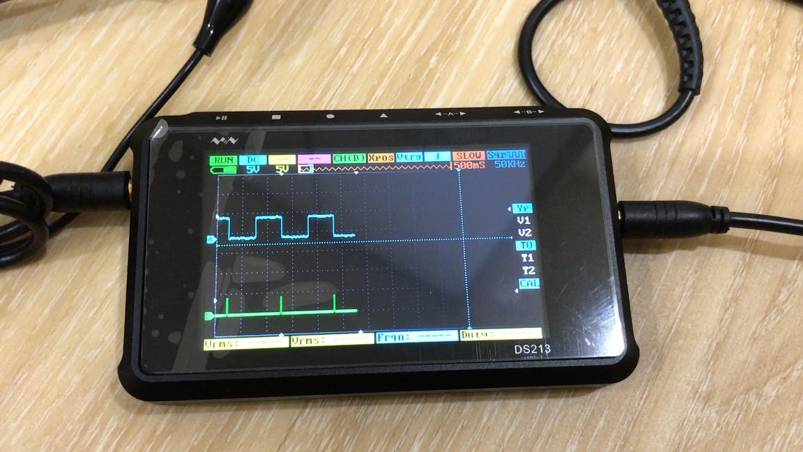
Result as seen from the oscilloscope :
CH A : The TRIG pin on my board send out a pulse of 5V HIGH to the HC-SR04 Ultrasonic Sonar Distance Sensor represented by the UP and the height represent a 5V. Then after 500ms, the TRIG pin pull LOW (flat) for another 500ms.
CH D : The ECHO pin on my board will receive a pulse from the HC-SR04 Sensor, as seen from the pulse captured from Channel D. The height of the HIGH pulse is slight less than 5V and came in around 500ms (estimated) after the sensor was activated.
The HIGH pulse width is very short. A few milliseconds.
Note 1 : Using the formula mentioned earlier with the pulse width and the velocity of sound (340M/S), we can calculate the distance.
Note 2 : [From the video] When I place an object in front of the sonar sensor, there seem to be no pulse in the ECHO pin... The ECHO pulse is too fast to be displayed, might be down to microsecond (us).
I bumped into a few problems along the way this week and found myself running out of time.
Problems faced :
1) I was looking for a 4-pin symbol in EAGLE, Fab Library, etc but couldn't find one.
2) When drawing a new 4-pin symbol in EAGLE, I ran into some errors.
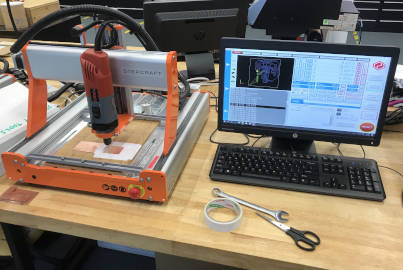
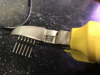
3) When etching the traces of the board, the FR1 board came out. The double sided tape was not holding the FR1 board well. So I pasted some tapes over the top of my FR1 board while etching the second time.
etc...
Programming the board :
It is easier to program using Arduine IDE and Arduino libraries. I looked at Neil's c code for the ultrasonic sensor, it is very 'low level', need to set the 'clock', then the 'timer', etc. So as I was running out of time, I learn to use the Arduino code first and try to get it to send data to the computer to be read by Python. I am new to Python programming and had to spend some time learning. Like to install Python 'PySerial' and running through some online tutorials. However the Arduino Serial Library took up 70% of the ATTiny44A Flash memory. If I have known this, I might have used an ATTiny84A with 8K Flash. In future, I think I would switch to c programming.
This week continues to build up my exprience and knowledge in electronics. This week was looping back to the previous weeks like reading of the ATTiny44A datasheet as well as the datasheet of the Input Devices. I began to design my own board this round. I was exploring on how to create my own symbol/part in EAGLE, but due to lack of time, I just modified an existing simliar part. I am happy that overall, everything went well this week.
My 'Hello HC-SR04' schematic design in EAGEL :
ultrasonic_sensor_lucas_2.sch
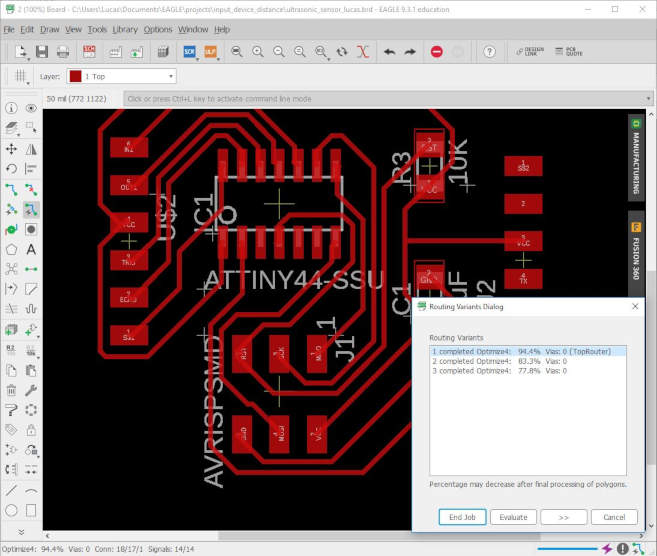
My 'Hello HC-SR04' board design in EAGEL :
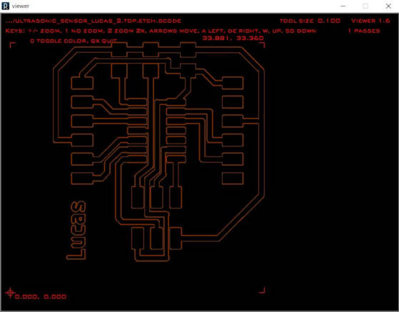
ultrasonic_sensor_lucas_2.brd
My Flash Programming code for my 'Hello HC-SR04' board :
Ultrasonic_sensor.ino
My first simple python code to read in the data from the serial port : Ultrasonic_sensor.py
Measurement of the HC-SR04 with an oscilloscope