

Week 11: Input Devices
Assignment
☒ Probe and input device's analog levels and digital signals
☑ measure something: add a sensor to a Microcontroller and read it
BRAINSTORMING
I had a sensor I wanted to use for my final project.
(actually, I wanted to use phototransistor, but my instructor told me that it was too simple for my final project, so we decided to strive for the harder)
How Accelerometer works
Accelerometer measures acceleration by measuring change in capacitance. Its micro structure looks something like this.
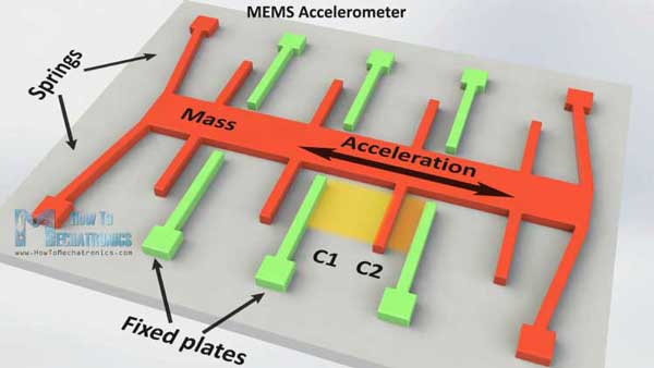 It has a mass attached to a spring which is confined to move along one direction and fixed outer plates. So when an acceleration in the particular direction will be applied the mass will move and the capacitance between the plates and the mass will change. This change in capacitance will be measured, processed and it will correspond to a particular acceleration value.
ADXL-343
So I had to research a butt ton of stuff about this sensor.

This is about the ADXL 343 accelerometer component we are going to use and the connection.
ADXL 343 accelerometer is a (MEMS :Micro-Electro-Mechanical System) by Analog device.
It is a 3-axis accelerometer with user selectable sensitivity & 10-13 bit resolution
(this depends on sensitivity)
It has 2 INT (Interrupt) pins:
INT pins when sensed on Arduino, pauses the system instantly, even when in the middle of something.
It supports:
SPI, (Serial Peripheral Interface)
I2C, (Inter-Intergral Circuit)
________________________________________________________________________________________________________________
SPI vs I2C
SPI
SPI connects single Master to single Slave
SPI bus requires 4 lines and each Slave requires 1 additional chip select i/o pin on the Master.
I2C
I2C only requires 2 qires vut the 2 wires can support up to 1008 slave devices.
I2C can support multi-Master system, which means it allows more than one Master
to communicate with all devices on the bus.
(The Masters cannot talk to each other, and must take turns talking on the bus.)
8bits of data and 1 bit of Metadata must be transmitted.
__________________________________________________________________________________________________________________
To use I2C connect the SDA (DATA) and SCL(Clock) lines to your Microcontroller board for communication.
( On Arduino, SDA is on Analog pin 4 , and SCL is on Analog pin 5)
(For more detailed read on ADXL343 and I2C, read page17 of ADXL343 Datasheet )
Probe and input device's analog levels and digital signals
We did not get to this at all. I was waiting for some of my classmates to show up so we could do this together, but they never showed...
Measure something using a sensor.
I had many options to do this... but I had spent most of my time trying to figure out and fix problems from previous assignments.
(I was finally able to bootload onto my fabkit...)
I started with designing a board

 I used Eagle and followed Niel's example, but I wanted my accelerometer to be in the center of the board because I was going to attach it on a bike helmet, and it would be ideal to have the board in the center.
 It was very difficult and I had to use a 0Ohm resistor for a jumper.
 when I put the finished( or so I thought) traces to make rml code, I found that the adxl 343 and the component pad was too SMALL!!! so I had to make many adjustments for it to be cut.
 I also put in three holes on (VCC), (GND), (I/O PWM) in preparation for output week.(Neopixels)


 Soldering was a whole new challenge. the adxl-343 is quite small, and the pads even smaller. I had to use combination of heat gun and soldering iron to solder the accelerometer on. I was quite successful.
 Here is where I got stuck. the voltage regulator started to heat up when I connected it to burn bootloader.
So I had to unplug and try to find out what the problem was...
The problem was that the power from ISP going to the ATTiny was going into the output of the voltage regulator,
making the flow backwards which meant there was a short.

 Then during Fan5 Saverio from Oshanghai told me that
 my ISP should not be powering my board,
and that I should unsolder the 0ohm resistor on my ISP
 (Before realizing the problem with the ISP)
I had bootloaded and uploaded code by unsoldering the voltage regulator and then soldering the voltage regulator on afterwards.
(Before realizing the problem with the ISP)
I had bootloaded and uploaded code by unsoldering the voltage regulator and then soldering the voltage regulator on afterwards.I uploaded the arduino example sketch in ADXL343 Library
#include <Wire.h>
#include <Adafruit_Sensor.h>
#include <Adafruit_ADXL343.h>
/* Assign a unique ID to this sensor at the same time */
/* Uncomment following line for default Wire bus */
Adafruit_ADXL343 accel = Adafruit_ADXL343(12345);
/* NeoTrellis M4, etc. */
/* Uncomment following line for Wire1 bus */
//Adafruit_ADXL343 accel = Adafruit_ADXL343(12345, &Wire1);
void displaySensorDetails(void)
{
sensor_t sensor;
accel.getSensor(&sensor);
Serial.println("------------------------------------");
Serial.print("Sensor: "); Serial.println(sensor.name);
Serial.print("Driver Ver: "); Serial.println(sensor.version);
Serial.print("Unique ID: "); Serial.println(sensor.sensor_id);
Serial.print("Max Value: "); Serial.print(sensor.max_value); Serial.println(" m/s^2");
Serial.print("Min Value: "); Serial.print(sensor.min_value); Serial.println(" m/s^2");
Serial.print("Resolution: "); Serial.print(sensor.resolution); Serial.println(" m/s^2");
Serial.println("------------------------------------");
Serial.println("");
delay(500);
}
void displayDataRate(void)
{
Serial.print("Data Rate: ");
switch(accel.getDataRate())
{
case ADXL343_DATARATE_3200_HZ:
Serial.print("3200 ");
break;
case ADXL343_DATARATE_1600_HZ:
Serial.print("1600 ");
break;
case ADXL343_DATARATE_800_HZ:
Serial.print("800 ");
break;
case ADXL343_DATARATE_400_HZ:
Serial.print("400 ");
break;
case ADXL343_DATARATE_200_HZ:
Serial.print("200 ");
break;
case ADXL343_DATARATE_100_HZ:
Serial.print("100 ");
break;
case ADXL343_DATARATE_50_HZ:
Serial.print("50 ");
break;
case ADXL343_DATARATE_25_HZ:
Serial.print("25 ");
break;
case ADXL343_DATARATE_12_5_HZ:
Serial.print("12.5 ");
break;
case ADXL343_DATARATE_6_25HZ:
Serial.print("6.25 ");
break;
case ADXL343_DATARATE_3_13_HZ:
Serial.print("3.13 ");
break;
case ADXL343_DATARATE_1_56_HZ:
Serial.print("1.56 ");
break;
case ADXL343_DATARATE_0_78_HZ:
Serial.print("0.78 ");
break;
case ADXL343_DATARATE_0_39_HZ:
Serial.print("0.39 ");
break;
case ADXL343_DATARATE_0_20_HZ:
Serial.print("0.20 ");
break;
case ADXL343_DATARATE_0_10_HZ:
Serial.print("0.10 ");
break;
default:
Serial.print("???? ");
break;
}
Serial.println(" Hz");
}
void displayRange(void)
{
Serial.print("Range: +/- ");
switch(accel.getRange())
{
case ADXL343_RANGE_16_G:
Serial.print("16 ");
break;
case ADXL343_RANGE_8_G:
Serial.print("8 ");
break;
case ADXL343_RANGE_4_G:
Serial.print("4 ");
break;
case ADXL343_RANGE_2_G:
Serial.print("2 ");
break;
default:
Serial.print("?? ");
break;
}
Serial.println(" g");
}
void setup(void)
{
Serial.begin(9600);
while (!Serial);
Serial.println("Accelerometer Test"); Serial.println("");
/* Initialise the sensor */
if(!accel.begin())
{
/* There was a problem detecting the ADXL343 ... check your connections */
Serial.println("Ooops, no ADXL343 detected ... Check your wiring!");
while(1);
}
/* Set the range to whatever is appropriate for your project */
accel.setRange(ADXL343_RANGE_16_G);
// accel.setRange(ADXL343_RANGE_8_G);
// accel.setRange(ADXL343_RANGE_4_G);
// accel.setRange(ADXL343_RANGE_2_G);
/* Display some basic information on this sensor */
displaySensorDetails();
displayDataRate();
displayRange();
Serial.println("");
}
void loop(void)
{
/* Get a new sensor event */
sensors_event_t event;
accel.getEvent(&event);
/* Display the results (acceleration is measured in m/s^2) */
Serial.print("X: "); Serial.print(event.acceleration.x); Serial.print(" ");
Serial.print("Y: "); Serial.print(event.acceleration.y); Serial.print(" ");
Serial.print("Z: "); Serial.print(event.acceleration.z); Serial.print(" ");Serial.println("m/s^2 ");
delay(500);
}
But I was not able to get a clear reading...
My suspicion is the problem with Attiny Library with Serial reading.My computer had been giving me trouble with Serial communication through FTDI. I later fixed it, but at this point, I gave up and tried it with another computer. My accelerometer board was recognized as a mouse for some reason. and was controlling Rico's mouse cursor.
Moving on
Because I had trouble with Serial communication with Attiny44/45
I decided to make a breakout board with ADXL343 that will plug into my FAbkit.
I found someone who had done this before, and apparently it worked!so I tried follow her.
Sophia Chung (WARNING:: there isn't any downloadable stuff. this was just an example.) The idea was to get rid of the Attiny and connect the I2C pins to my Fabkit.
Sophia's example looked too simple, but since she said it worked, I will try it too.
She uses one capacitor 0ohm jumper and connects the INT SCL, SDA, VIN, and GND pins
I though it would need pull-up resistors but I decided to follow this for now.


 I connected it to my fabkit (GND, VCC, SCL [A5, SDA[A4])
 When the connection was slightly off, it tells me to check the wiring.
 When I finished connecting everything, the Data that the sensor read did come up,
but it was broken before I got a chance to document it...
and now all it does is show the screen above with no reading... I had tried changing the components to a new one,
checking with multimeter to check everything...
But could not figure out what the problem was... I think I will try Janin Rubinobitz's example next time to explore more.
Seriously Moving on
I finally gave up and moved on to using a factory made breakout board.

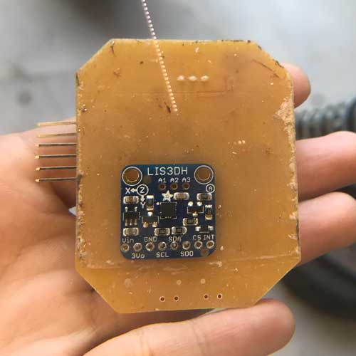
 There was an LIS3DH breakboard given to me by TEX!
Very simple connection.(I2C)
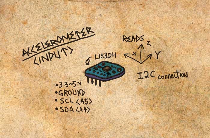
 LIS3DH is also available in both SPI and I2C. so with your connection and code,
you can choose which is more effective for what you want to do.
above is example code from LIS3DH library to read the Axis data from your accelerometer sensor. Success!!! [June 2019] This input was used for my Final Project
EXTRA
There is just too much I have to do still, and I am feeling super overwhelmed. lol.
[as of March.2019]
The fun thing about some Accelerometer is that they have gyroscope function,or temperature sensor function ( why together with axis sensing?)
