This week, I have to make something big with the CNC machine. It is my first time to use the CNC, so I won't be designing something really sophisticated.
I got inspirations from different application of the ShopBot machine.
CNC stands for Computer Numeric Control it is a process used in the manufacturing sector that involves the use of computers to control machine tools. Tools that can be controlled in this manner include lathes, mills, routers and grinders.
The process involves creating a CAD(Computer Aided Design) file of the desired object. Then a specialized CAM (computer aided Manufacturing) software is required to convert the 3D CAD file into a set of codes which the machines can understand. CNC machining language, called G-code essentially controls all features like feed rate, coordination, location and speeds. With CNC machining, the computer can control exact positioning and velocity.
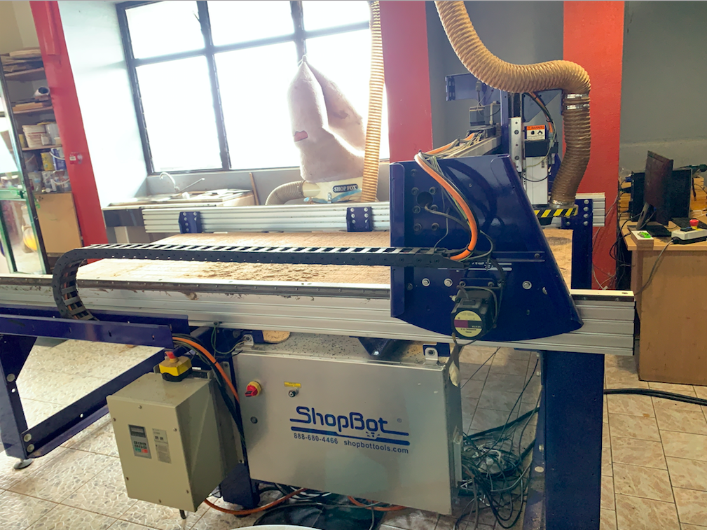
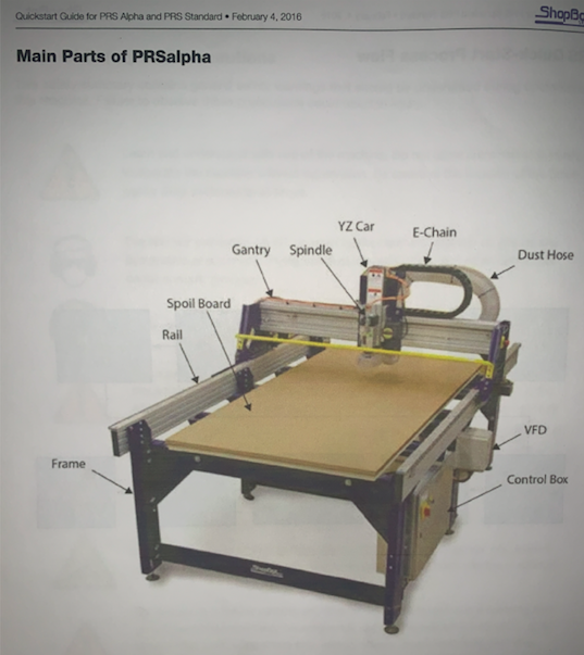
Shopbot is a large format CNC machine which can be used to cut timber, plywood, soft aluminum etc. It is a 3-axis machine and has a bed size of 4x8 feet. Learn more here.
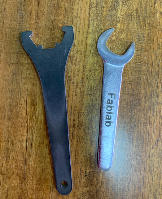
The Spanners, to fix the Collet and Covernut
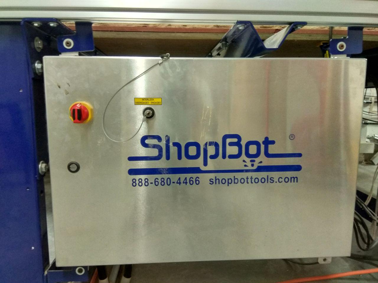
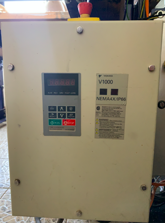
The Control box
The Power Distribution Box
The Vacuum System

The ShopBot have a Powerfull Vacuum Clear to collect all dust that comes when we cut something , it's very helpfull.

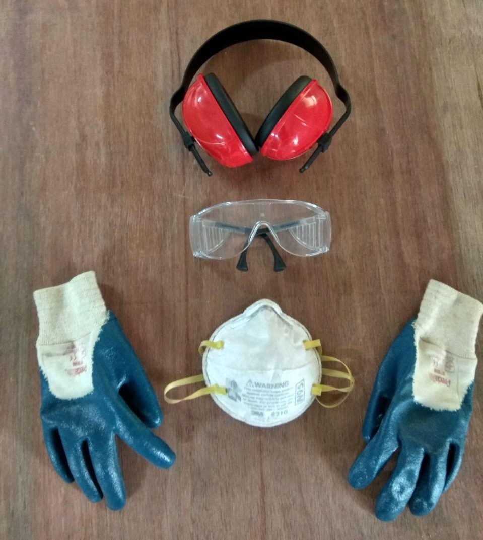
Working with a big machine such us the Shopbot, we need to protect ourselves as well.
Below are the basic Self-protection equipments
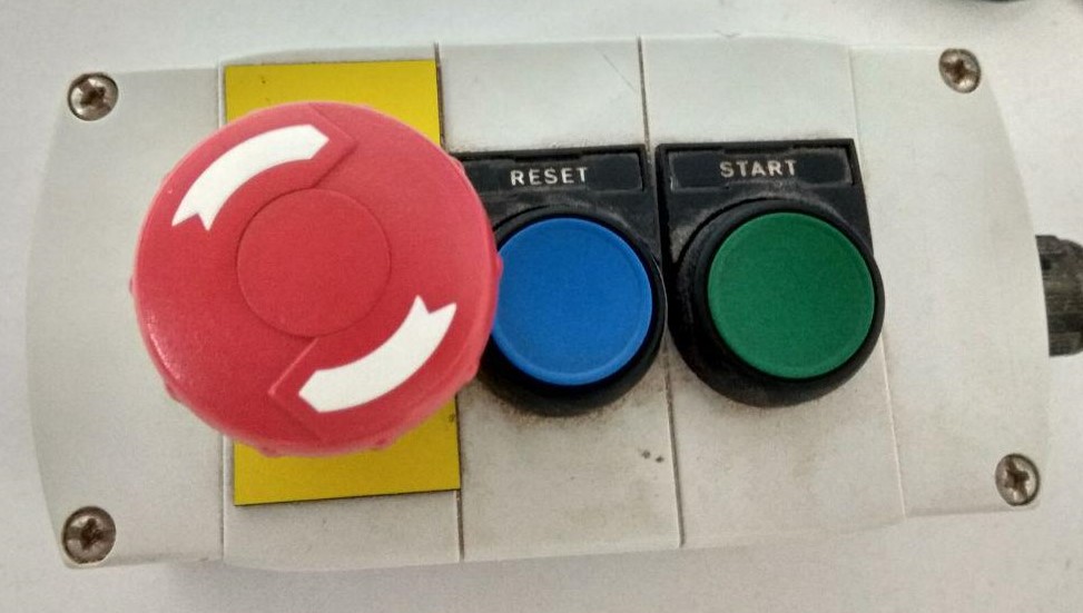
ESTOP switch is Emergency STOP switches are used for stopping the work during emergencies there are two emergency stop switches will be there, One is ESTOP box which contains two additional switches one for Starting the spindle and the other for Reset. Ensure these ESTOP switches are in the OFF position position by rotating the RED STOP button on the DONGLE COUNTER CLOCKWISE .
Bit material: Router bits used in Shopbot are made from a variety of materials such as solid carbide, carbide-tipped steel, and high-speed steel.
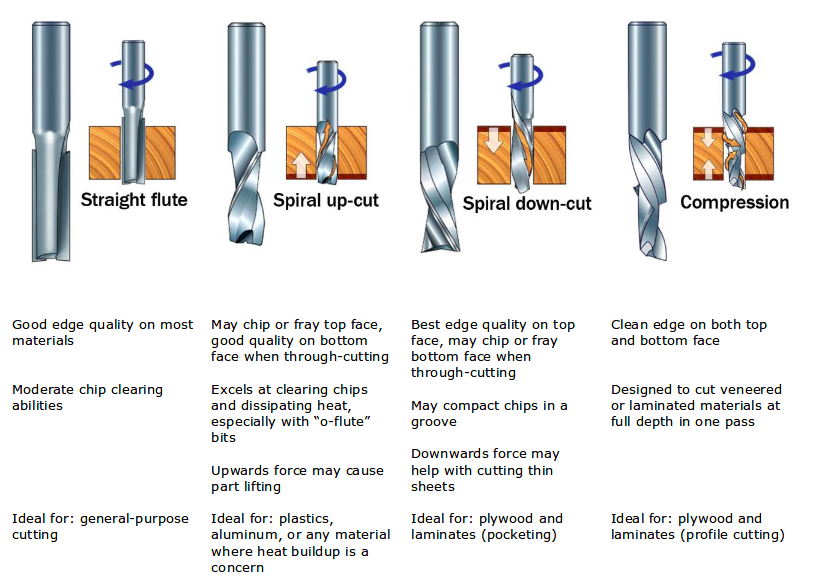
Flute type : There are four basic flute types: Straight, spiral up-cut, spiral down-cut, and compression
Drill bit Vs End mills : A drill bit need to cut straight into the material hence will have teeth at tip. But an End mill needs to cut from the sides also, that means it needs to have a cutting edge spiraling all the way up to the flute.
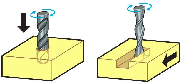
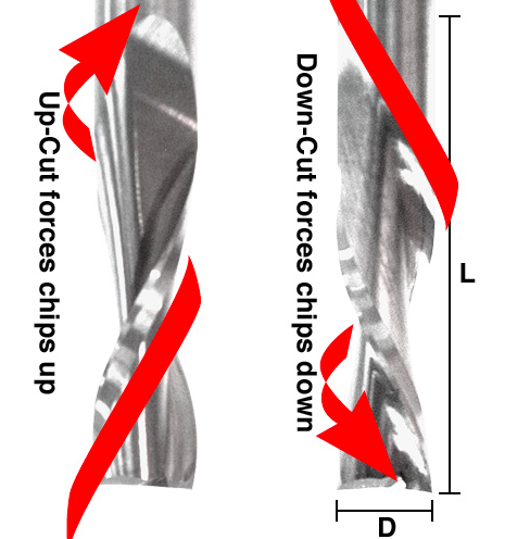
In an Upcut type end mill the teeth on the flute will point upwards. This means that the end mill is cutting and drawing out the wood through the flute. This is good for cutting deep into the stock. But this leaves a bad surface finish on the top of the surface.
A downcut type end mill has teeths that point downward on the flute. This means that the end mill will cut and try to push the material into the stock. This will give good surface finish on the top, but it is not very efficient at removing material.
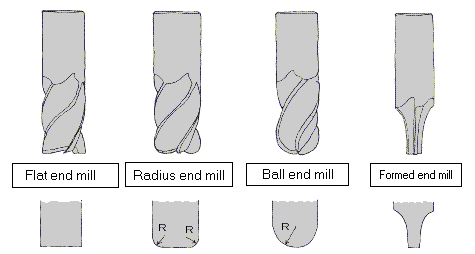
flat end leaves flat surface profile on the stock and are good for removing large volume of material, but steps are formed when used for making curved surfaces. Ball end leaves curved surfaces and forms smooth curved finish while cutting cavities. They are used for finishing cuts.
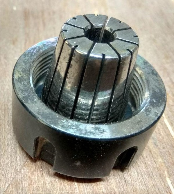
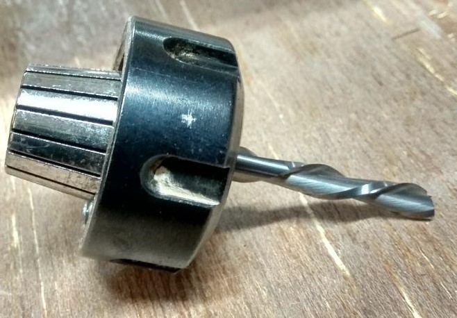
A collet is a subtype of chuck that forms a collar around an object to be held and exerts a strong clamping force on the object when it is tightened. It may be used to hold a workpiece or a tool. We are using ER25 collets, ER collets are slotted (alternately) from both ends and therefore compress onto the cutter along the whole length of the collet when tightened. This not only provides a better grip on the cutter shank but also allows some variation (typically 1mm) in shank sizes that may be used in a single collet. The smaller size collets are best used to hold cutters no more than 0.5mm below the nominal size. Collets are inserted into the covernut.
Chipload is the size of the chips which are being produced during cutting on the machine.
Chip Load or Feed Per Tooth is the theoretical length of material that is fed into each cutting edge as it moves through the work material. The goal for calculating the proper chip load is to reduce heat and increase productivity while promoting long tool life. When the chip is too small, heat is transferred to the cutting tool causing premature bit failure. Too high of a chipload will cause poor edge finish, and transfer cutting load or thrust to the part, possibly causing it to move. The chipload shouldn't be too small (sawdast) since it can cose overheating of the bit. It also shouldn't be too big since this can cose scraggy surface finishing. A bit in good condition and running at recommended loads will be at room temperature when a cut is finished. More flutes create a smoother surface finish, while fewer flutes remove material fastest, but make rougher cuts. Proper chipload is important because chips dissipate heat. Hot cutters can lead to suboptimal results, including burned wood, a poor edge finish and dull tooling. Chipload is dependent on the Bit size you are using and the cutting speed.
There are many tables that help you choose the chipload of the job you want to do, which will be needed to calculate the speed of the router. The image below represents one of the chip load charts available online.
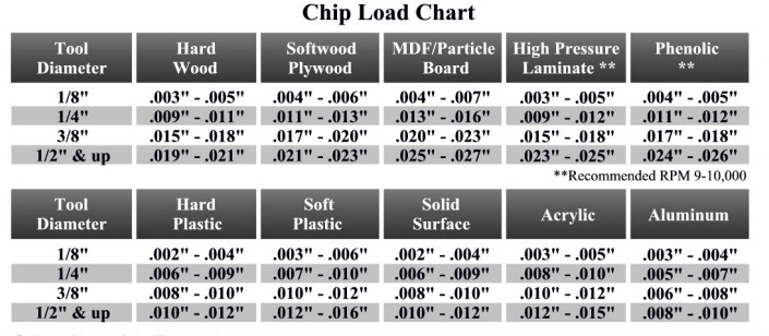
Please note that those represent a specific kind of milling bit. Specific loads for your tools can be obtained from your router bit manufacturer.
The speed at which we move a cutter across the material is called the Feed rate.The rate of rotation is called speed and is controlled by how fast the router or spindle turns the cutting tool. Both feed rate and spindle speed will vary based on the material being cut. A general rule of thumb is that you want to move the tool through the material as fast as possible, without sacrificing surface finish. The longer the tool rotates in any one place, the more heat that builds up. Heat is your enemy and can burn your material or radically decrease the life or your cutting tool.
Feed rate vs spindle speed: Spindle speed which is too fast paired with a slow feed rate can result in burning or melting. Spindle speed that is too slow paired with a faster feed rate can result in dulling of the cutting edge, deflection of the end mill and possibility of breaking the end mill.
Even though you might know the value of speeds and feeds for some materials, it's important to know how to calculate them in case you have different materials. The formula is as following:
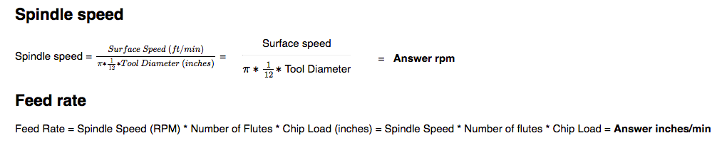
BUT! Instead of doing complicated calculations, we can use Fablab Speed and Feeds Calculator.
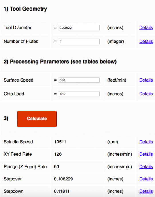
After filling in the values for 6mm one flute tool, and taking the surface speed and chip load for OSB material (there is no foam board but values for OSB should workas well) I'm getting the result similar to one I got from my colleagues.
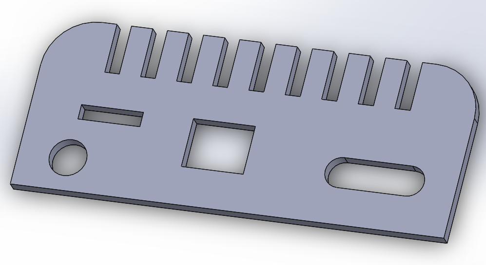
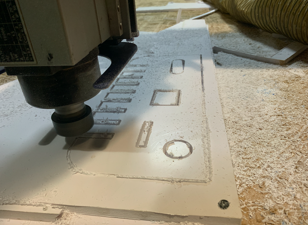
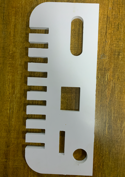
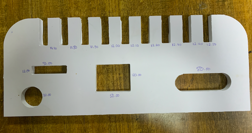
I Deigned a test design to learn about the machine tolerances.
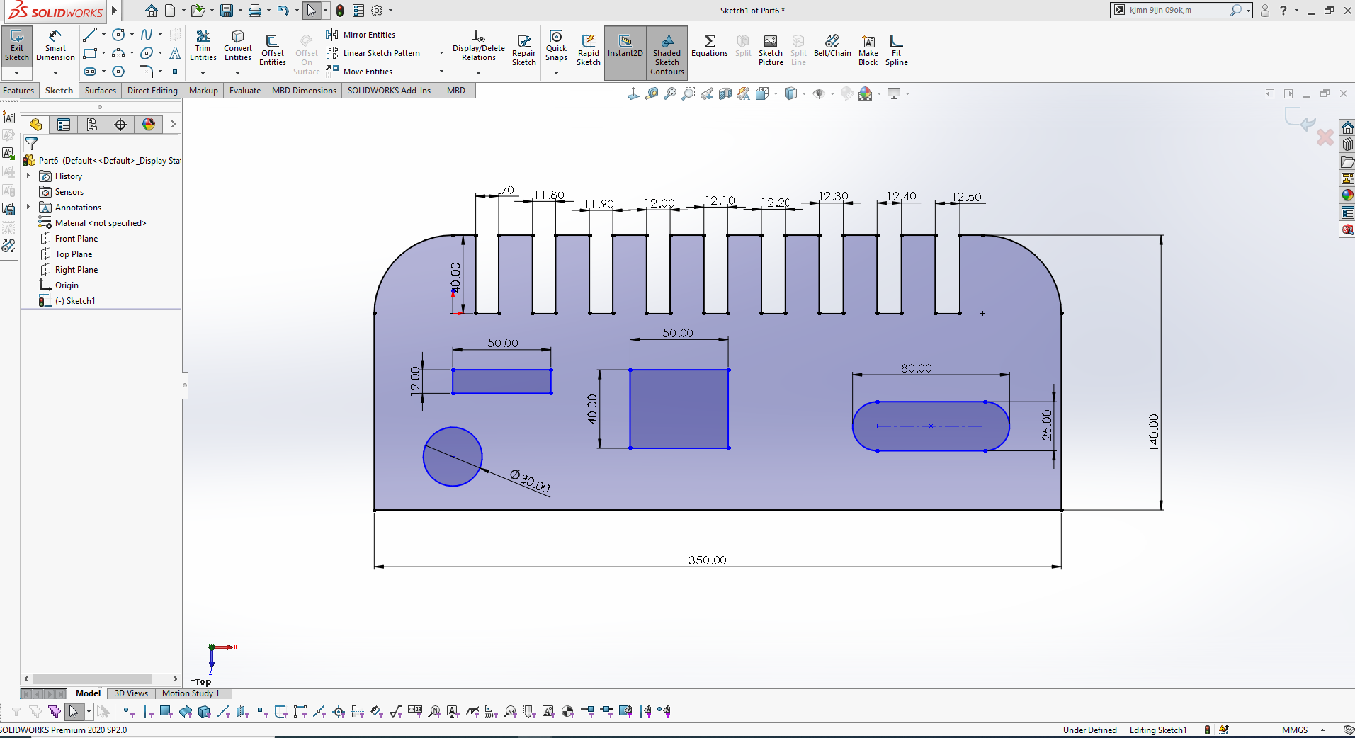
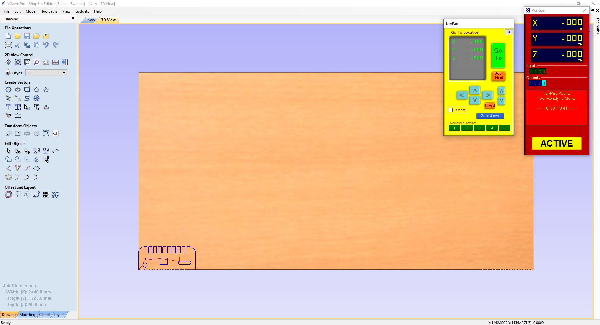
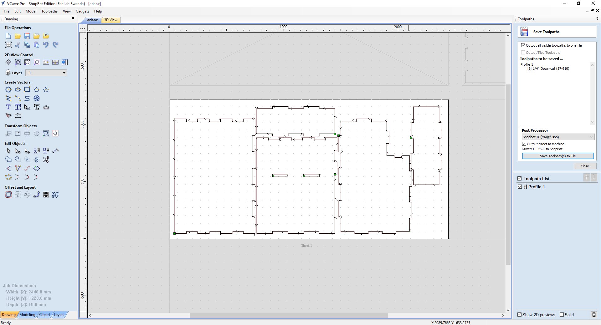
Imported the design in Vcarve software to generate the Gcode, after I set the axes position using the official shopbot software.
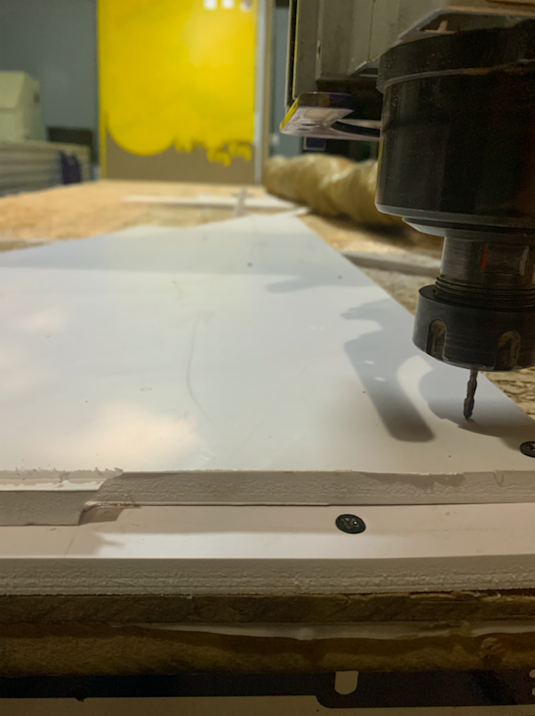
Cutting ...
TEST HERO SHOT
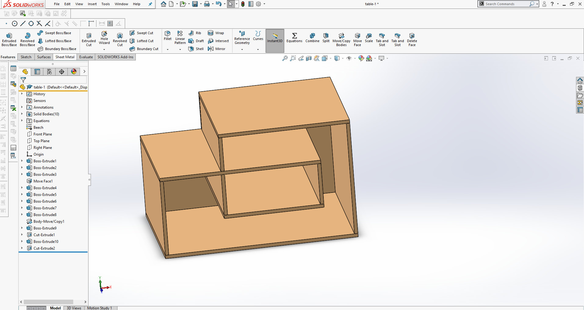
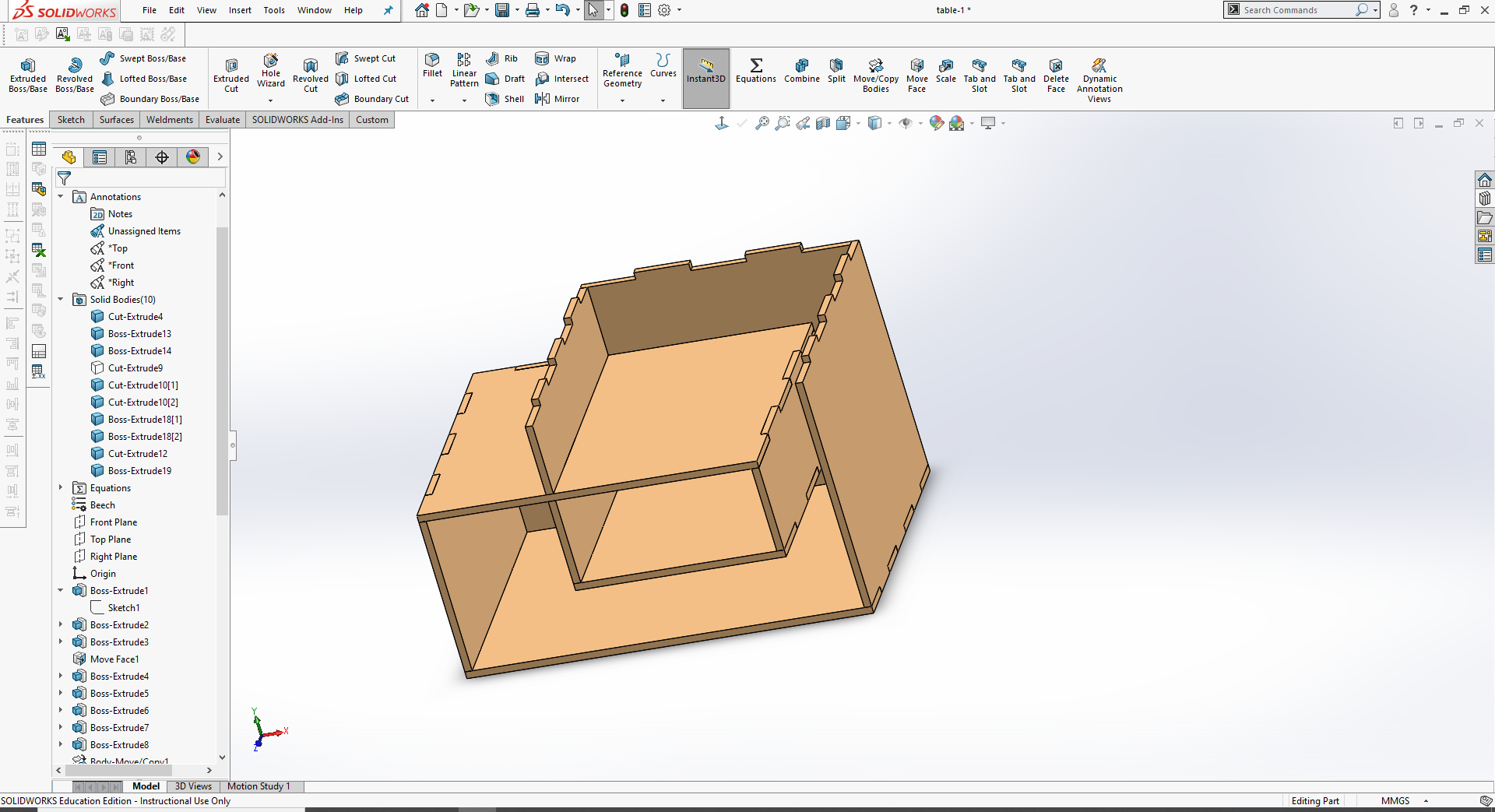
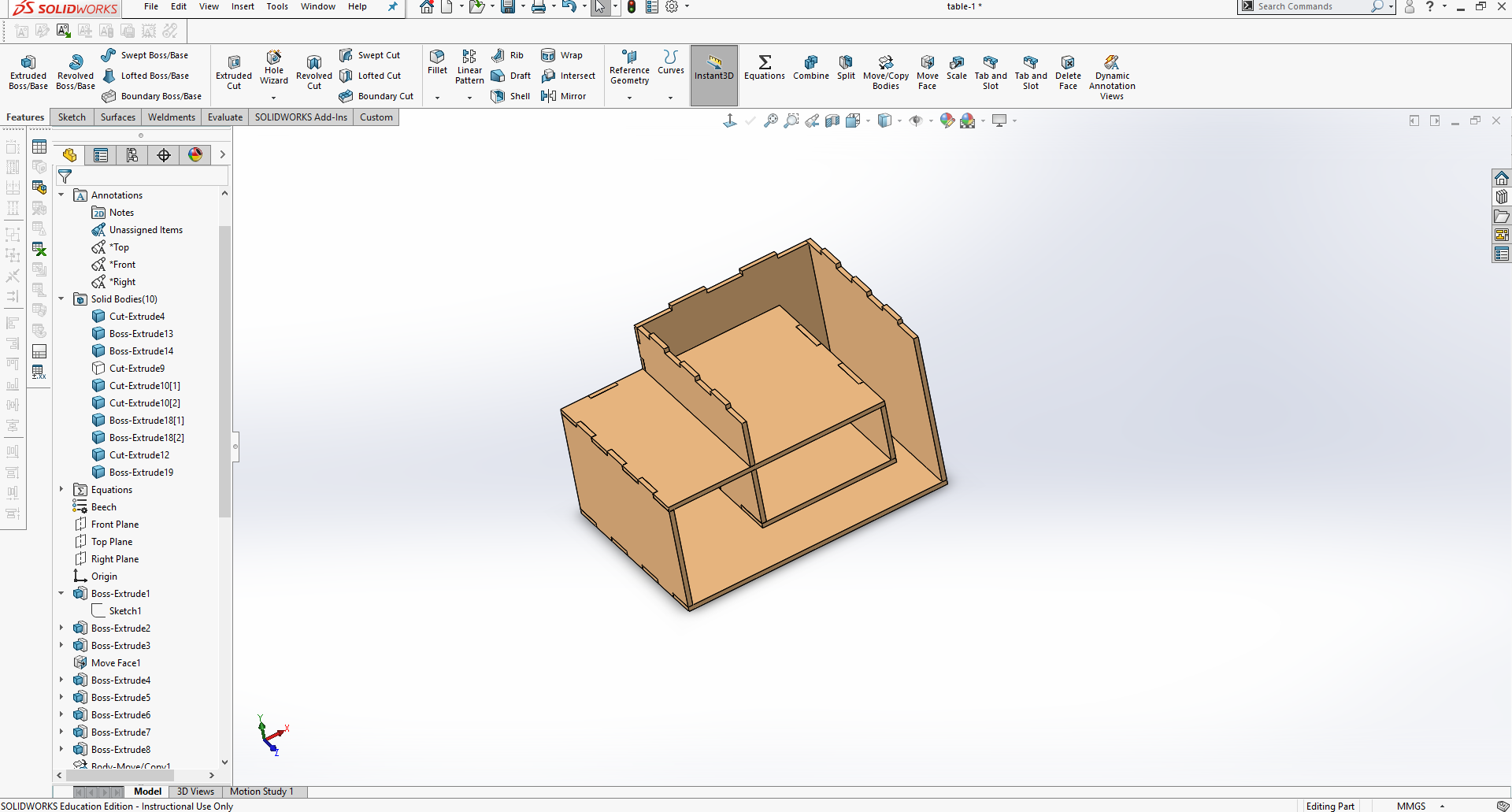
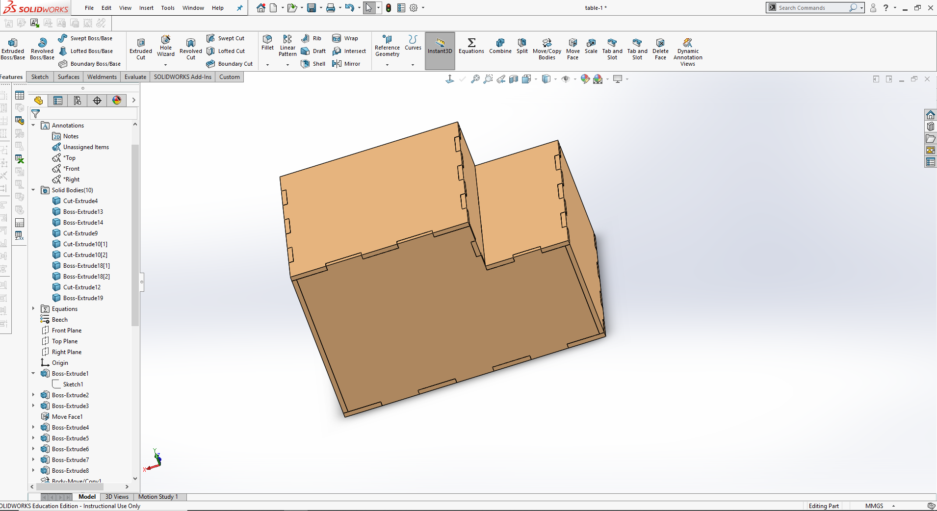
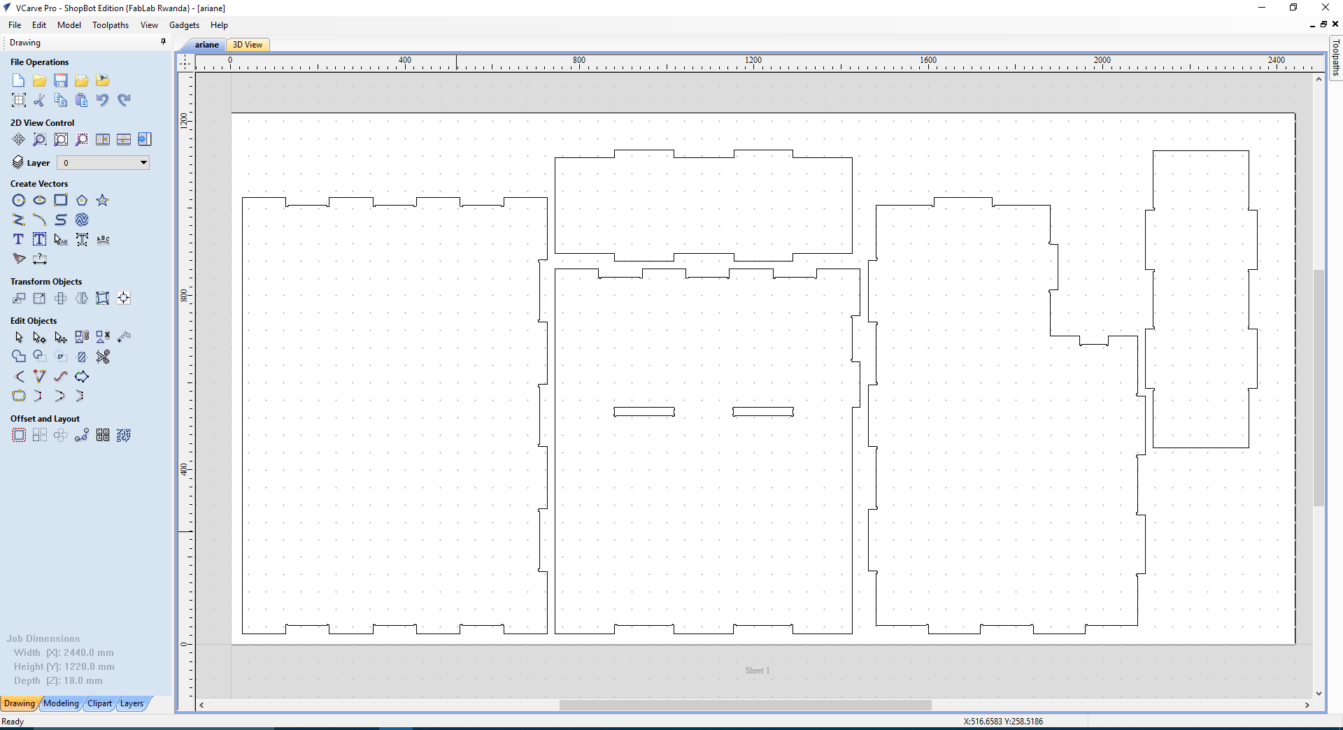
I designed and made a bedroom table.
Below are the parameters I used:
2D outline tool path
. Cut depth = 15.5mm ( board thickness + 0.5mm)
. End mill = 1/4'' Down-cut(57-910)
. Speed 12,000 RPM (Spindle Rotation Speed)
. Feed 3.0inch/second
. Vector processing = Outline
. Add Tab
Pocket tool path
. Depth = 5mm
. End mill = 1/4'' Down-cut(57-910)
. Speed 12,000 RPM (Spindle Rotation Speed)
. Feed 3.0inch/second
. Clear pocket = offset
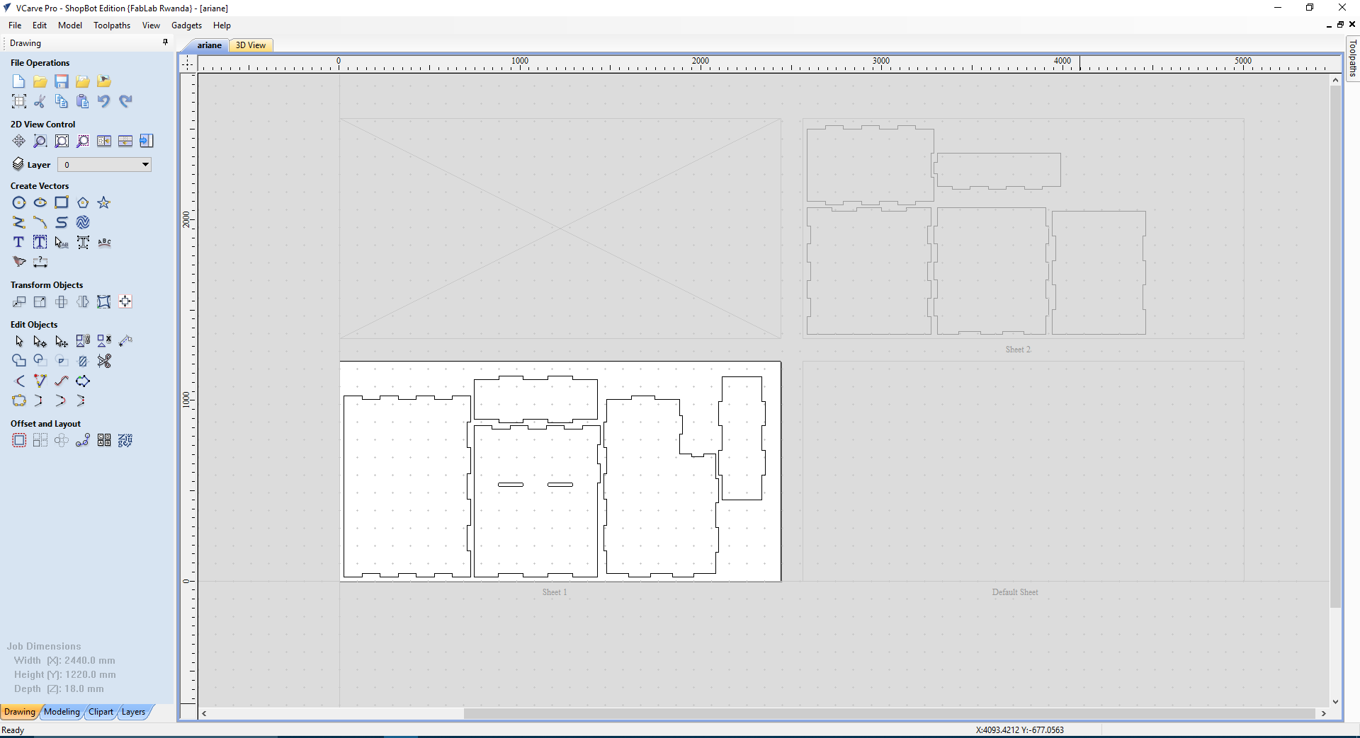
My design went on 2 MDF sheets
Select and add tabs
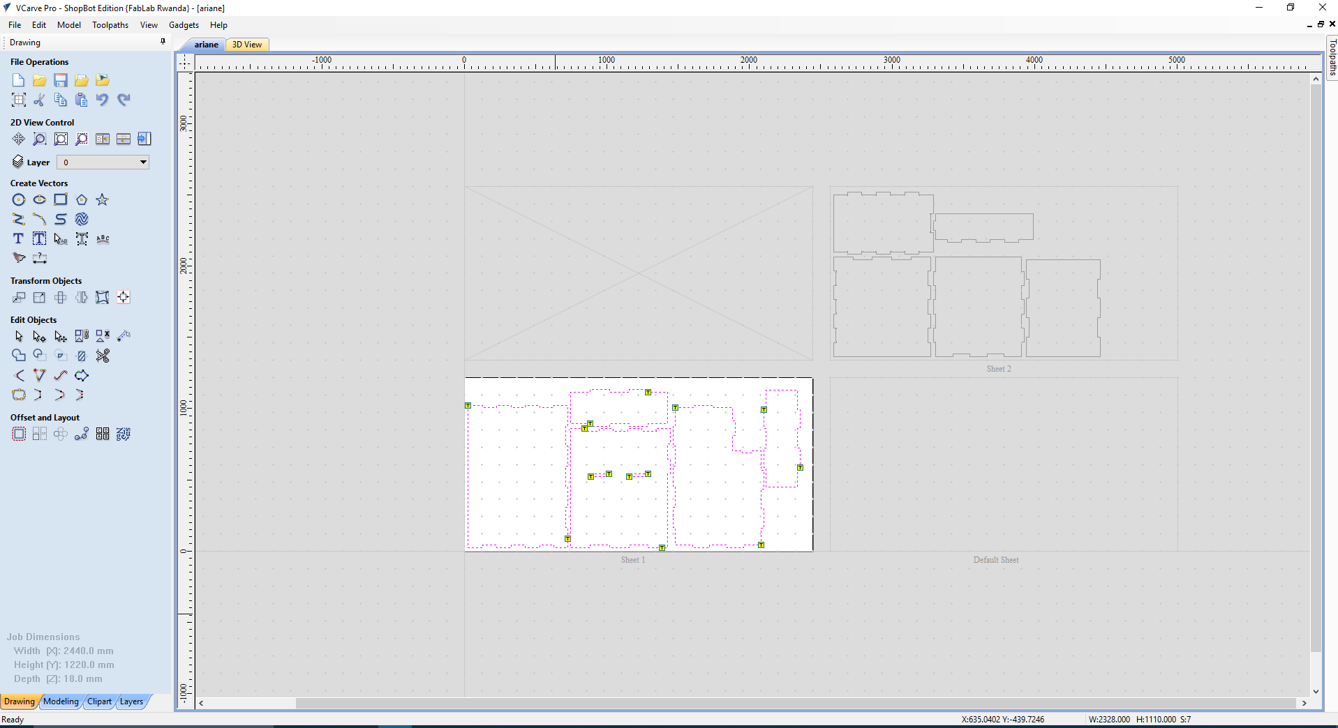
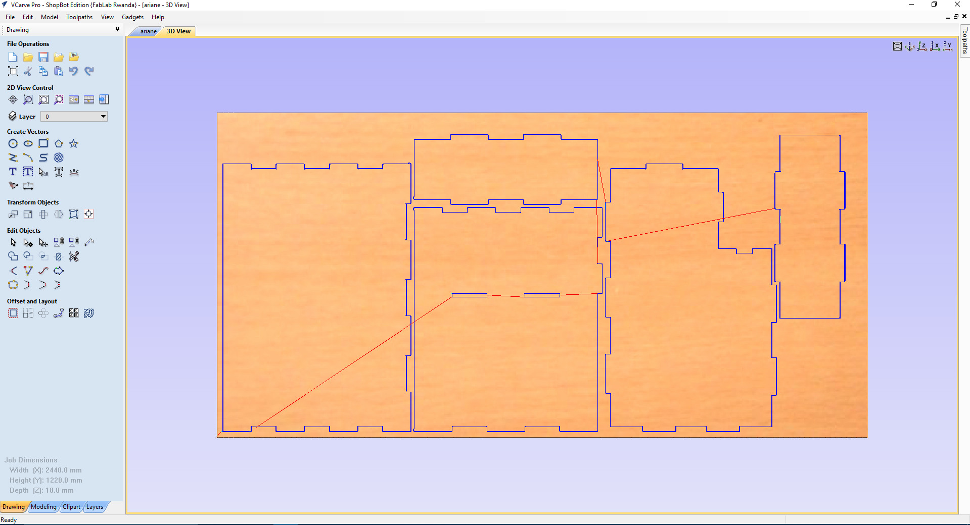
Then, generate the tool path and cut.
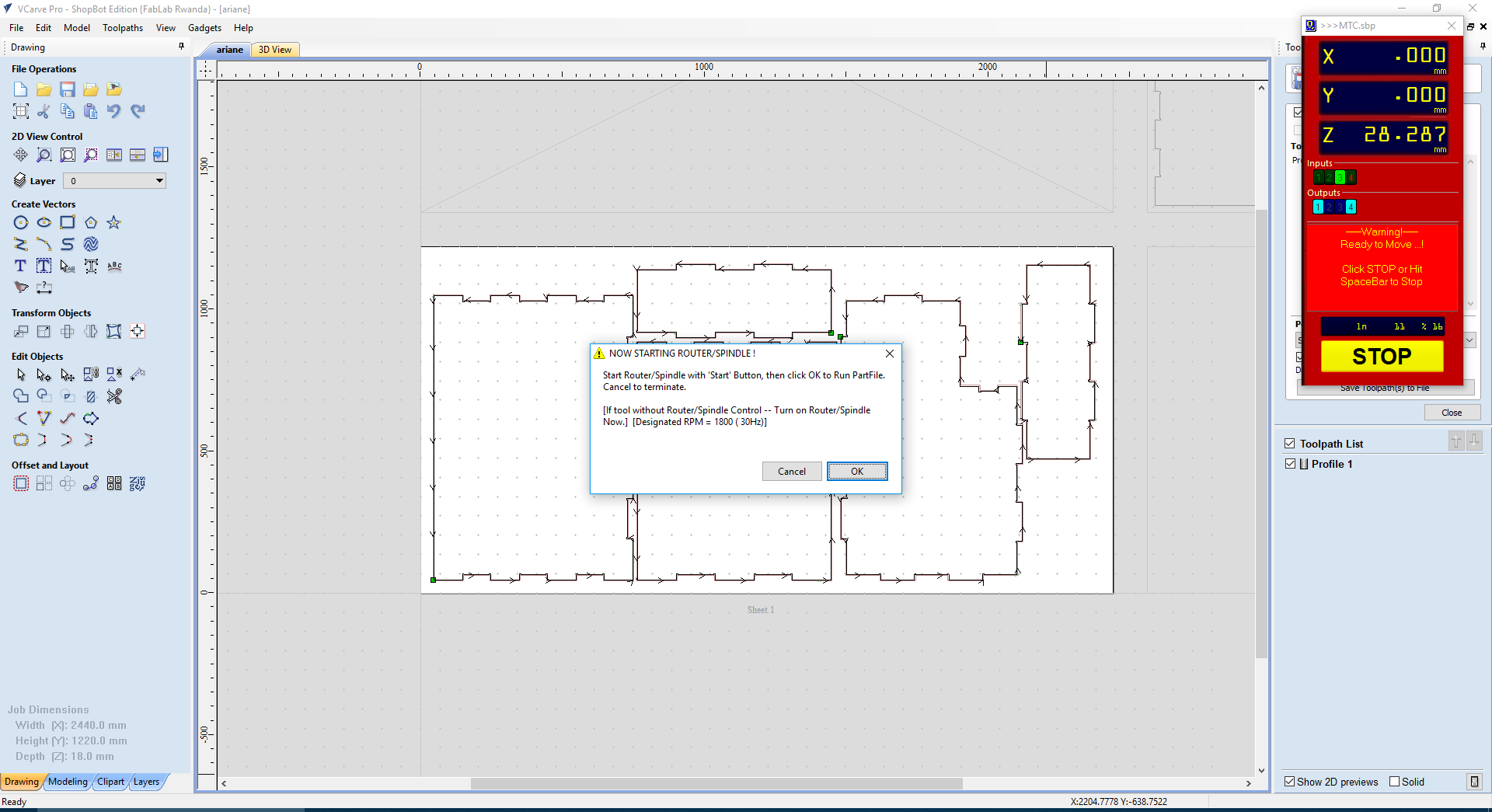
Next is start the Shopbot and Set the X and Y Axis/Orgins, in here we are using Official ShopBot Control Software for this.
Making sure that my MDF is set very well

With the help of the Driller, I fixed the MDF with screws

RESULT AFTER CUTTING
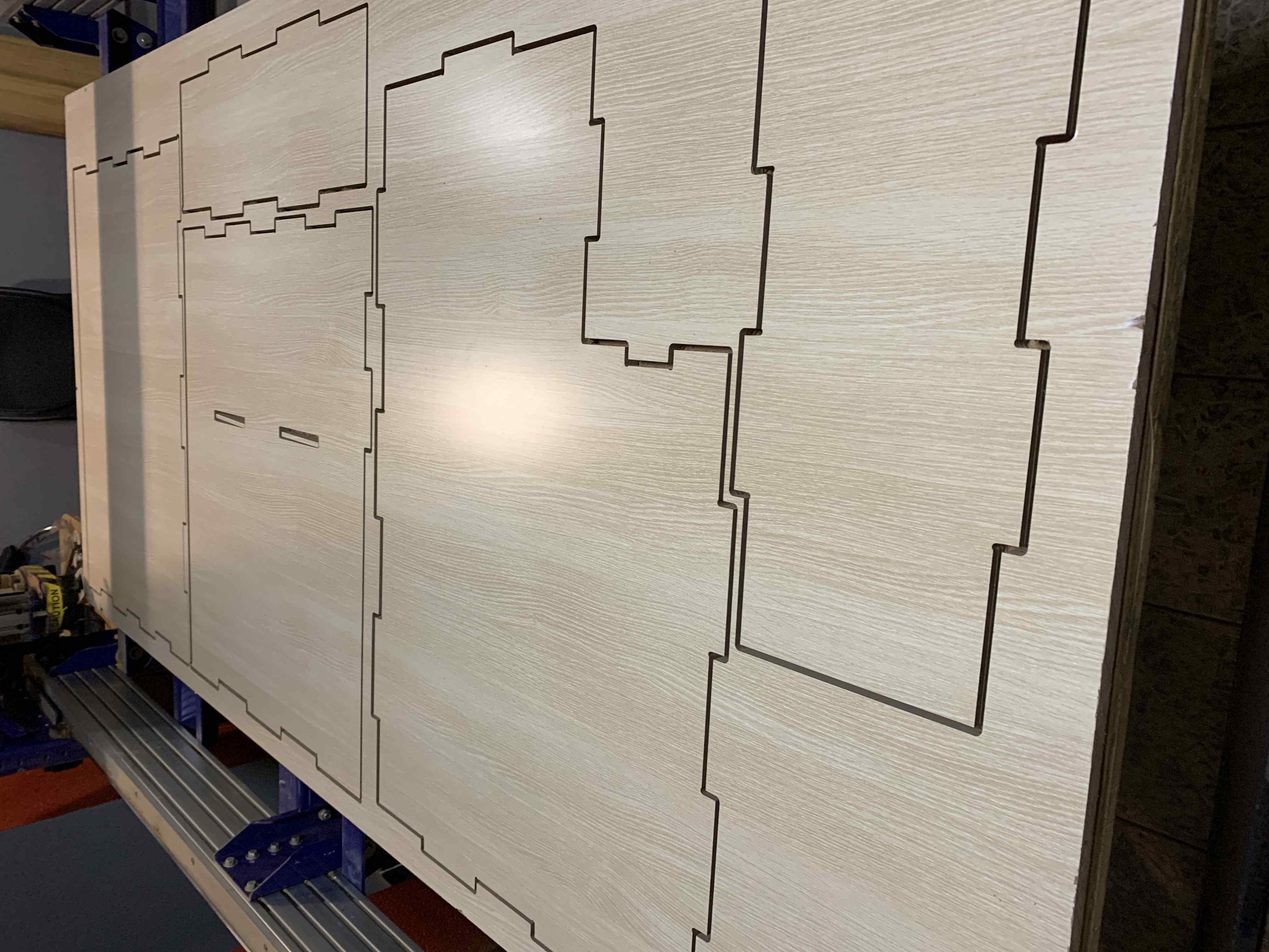
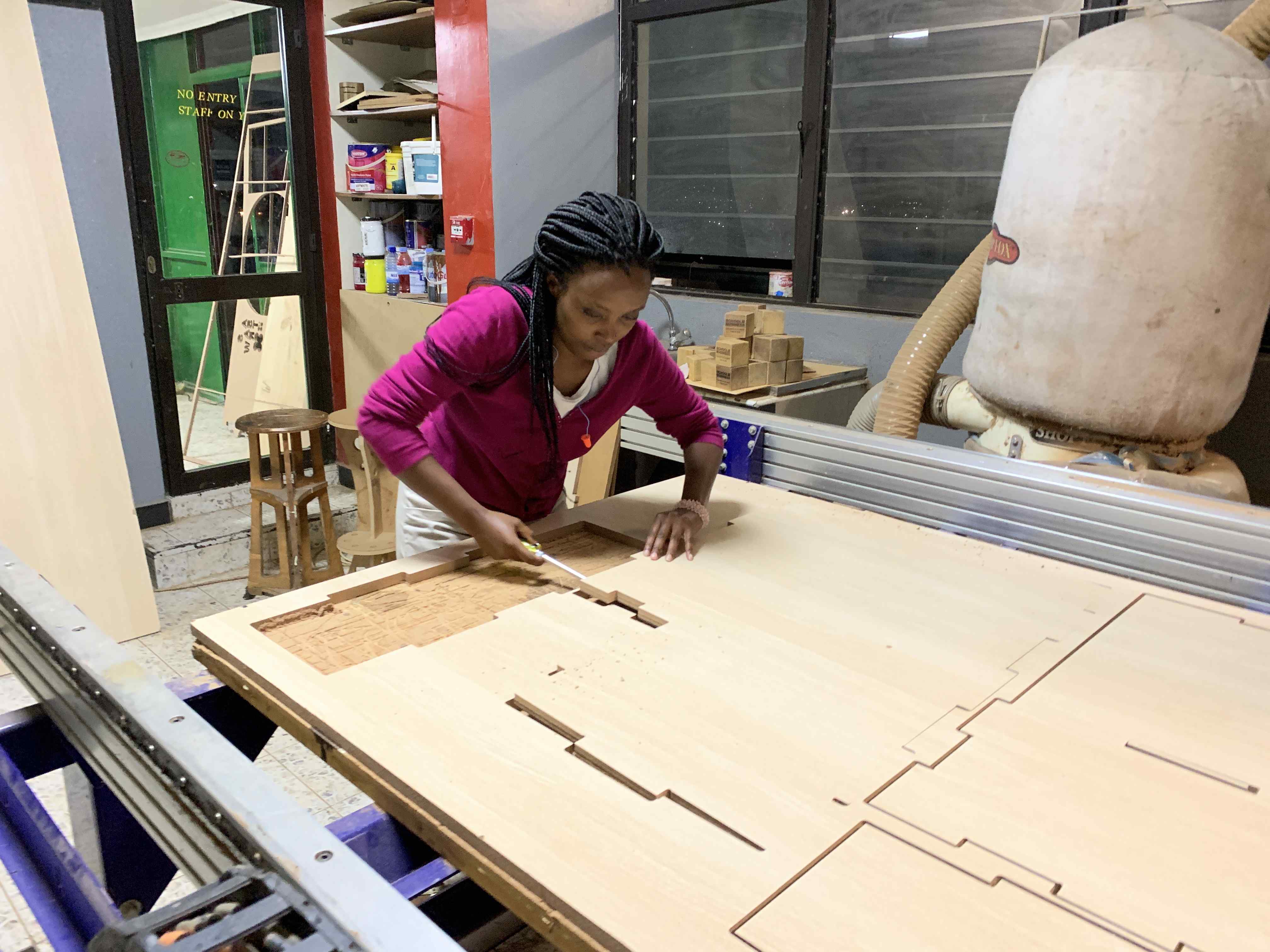
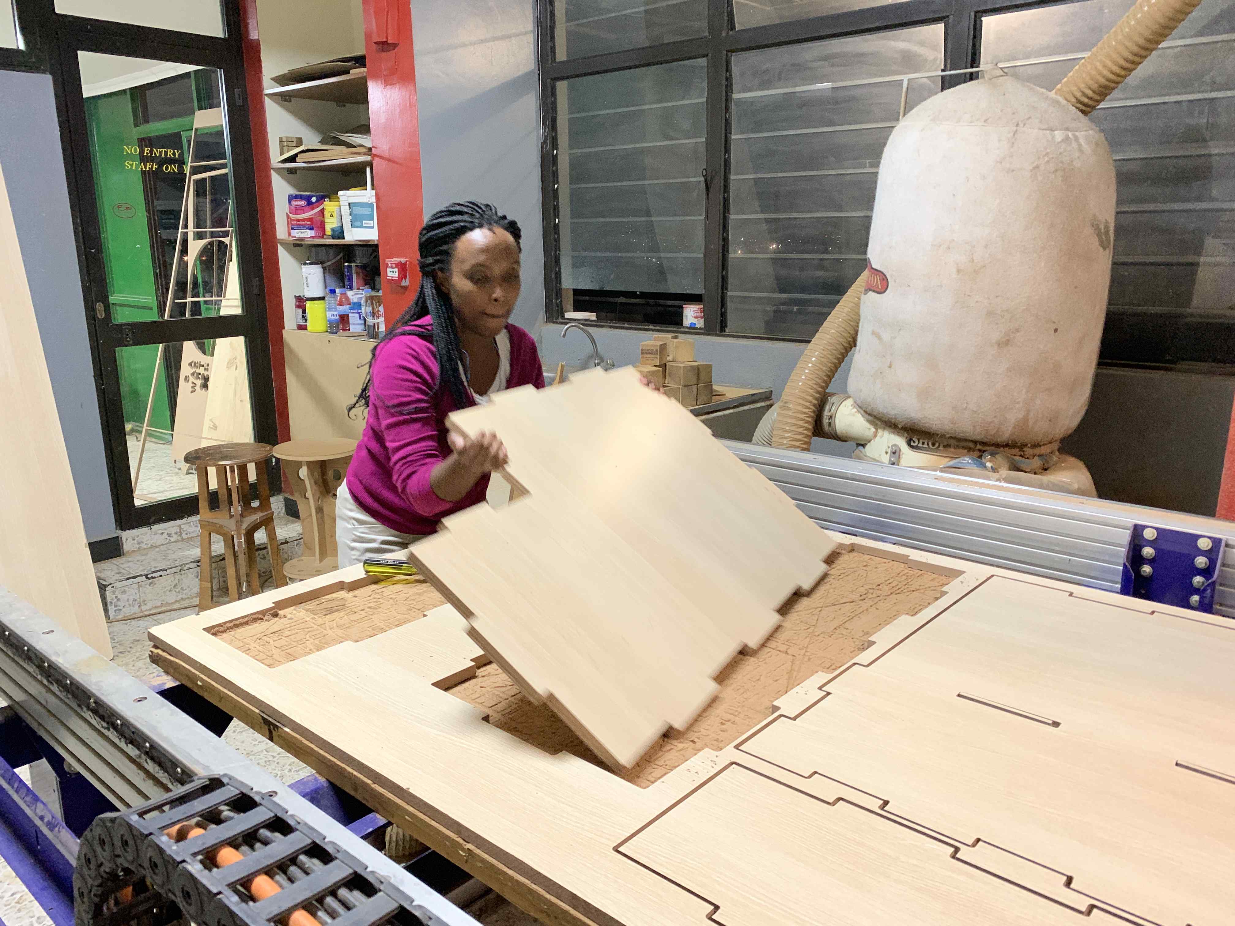
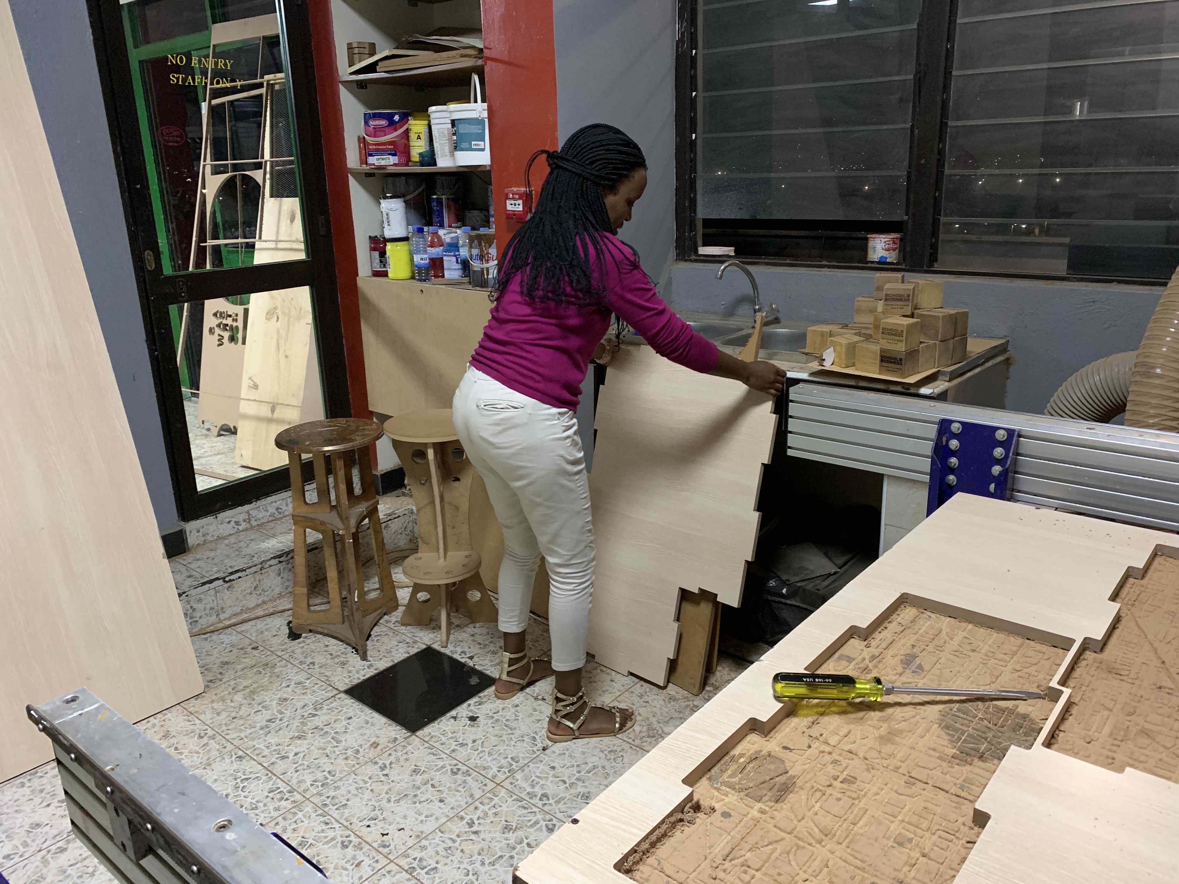
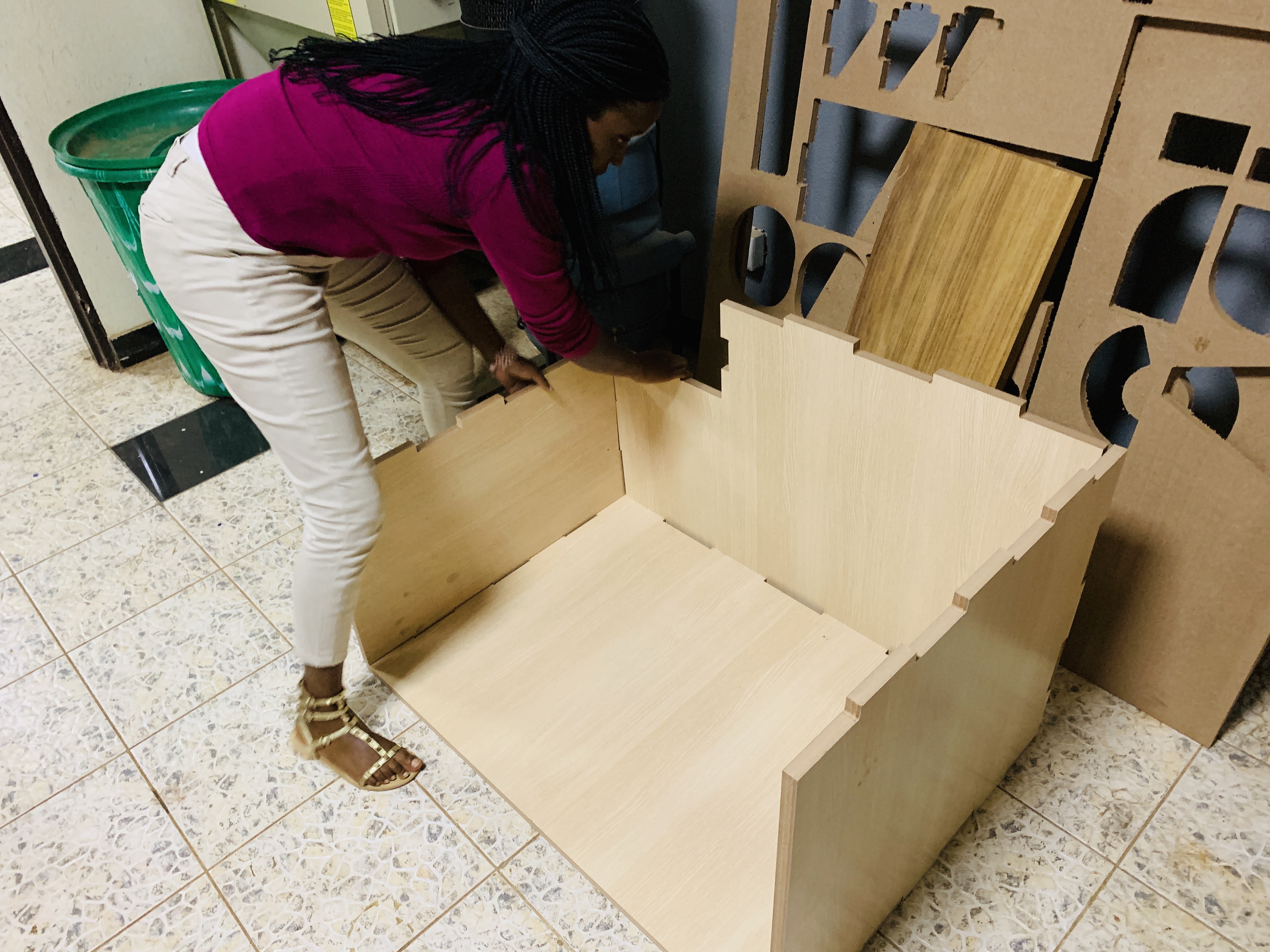
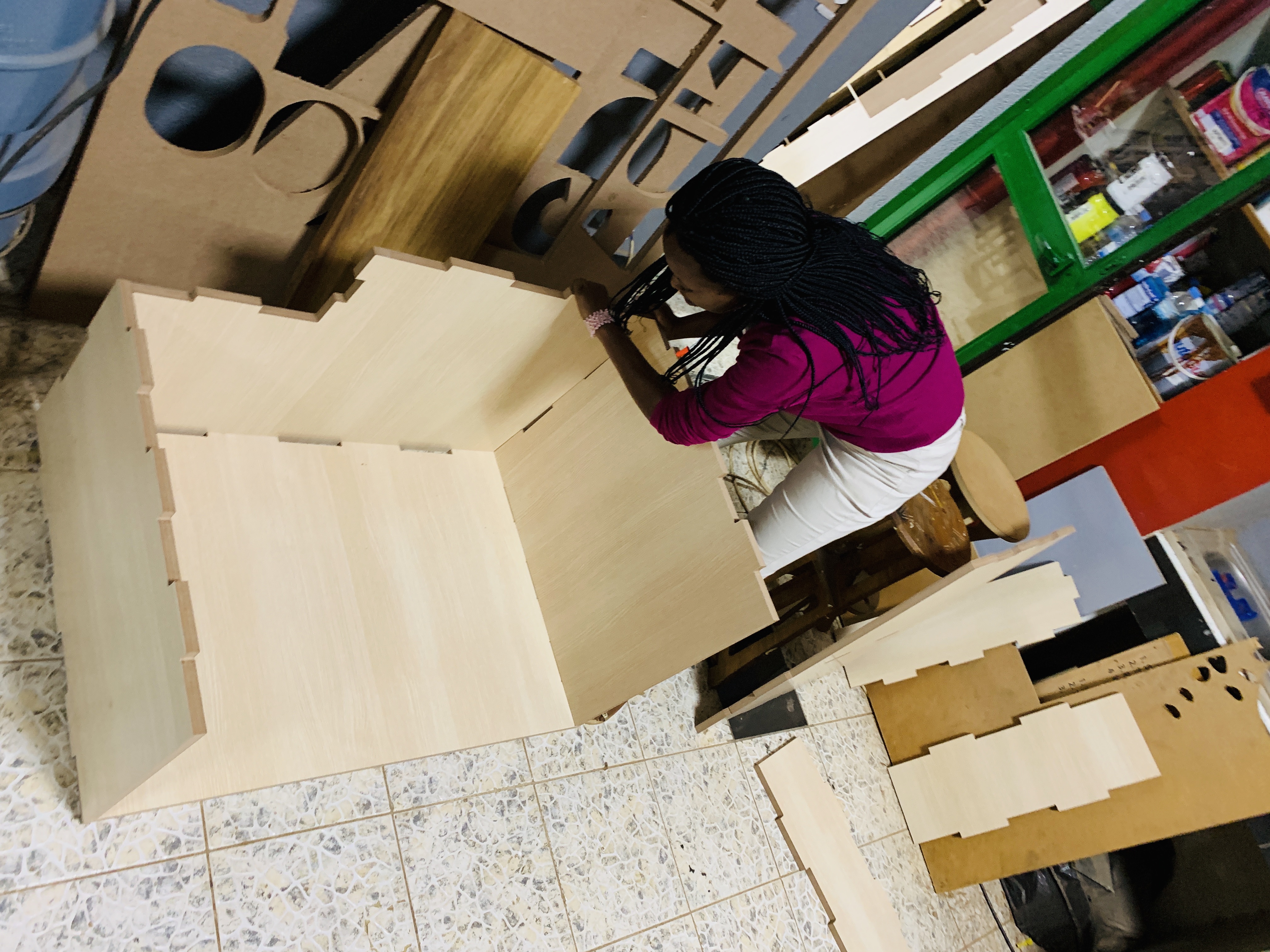
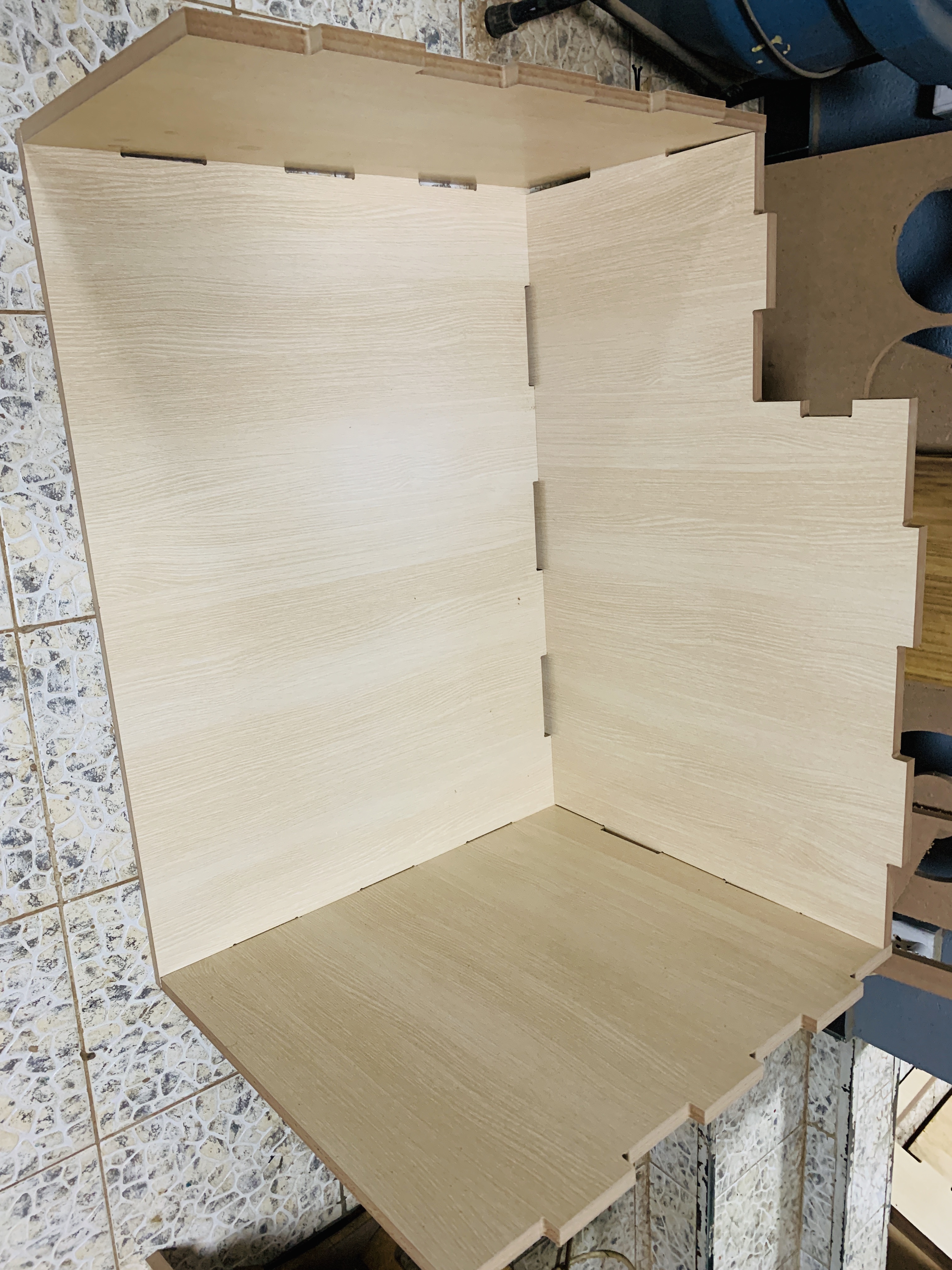
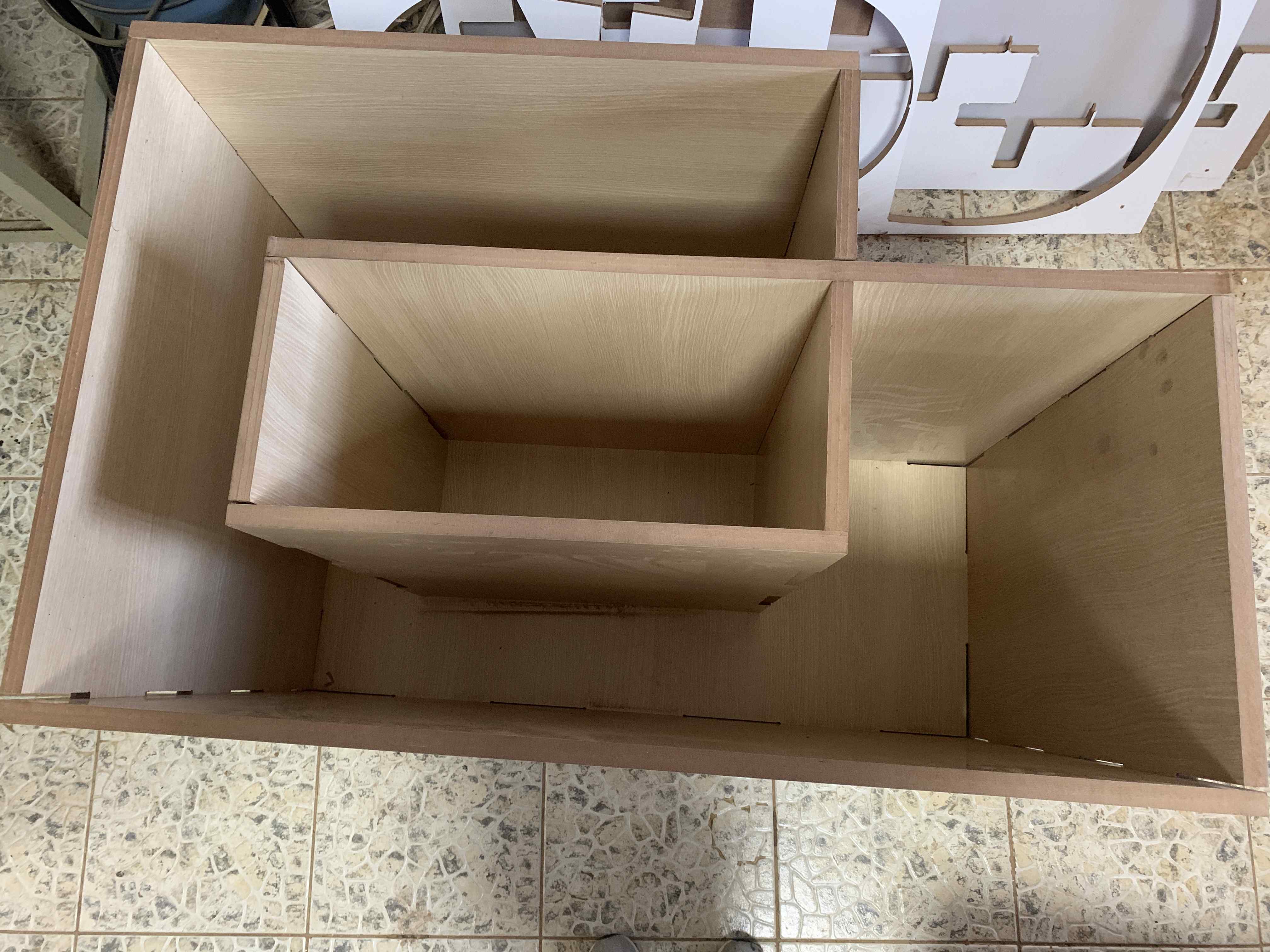
It was a hard job but I MADE IT !
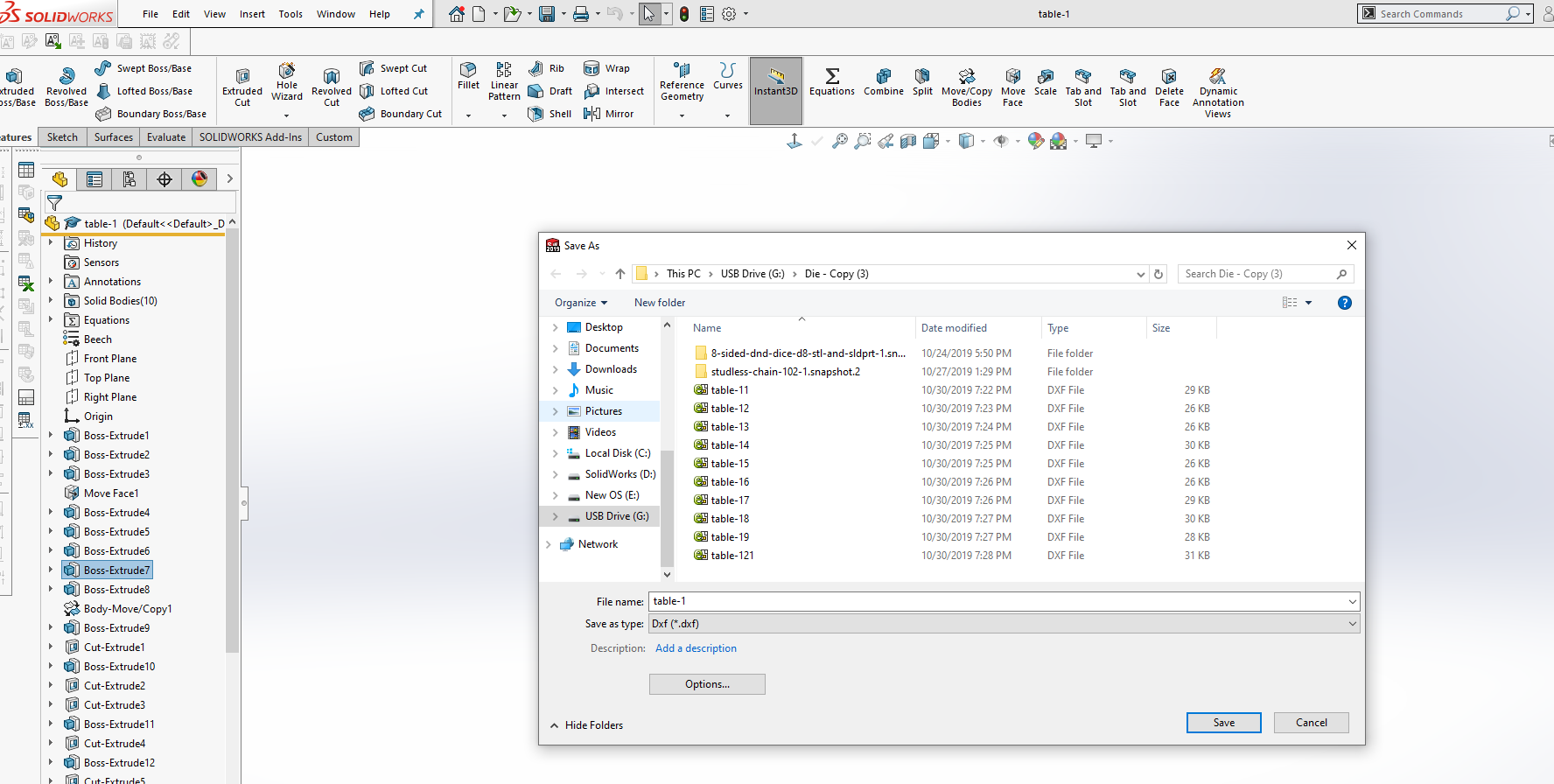
Files: