This week, I learned a different circuit design software other than eagle, KiCard. I also explored TinkerCircuit, a simplistic circuit designer marketed toward children. This helped me to comprehend the connections and arrangement of the different components. TinkerCircuit actually lets you export your design as a .brd file which is what Autodesk Eagle uses.
Here is a tutorial you can use to learn Eagle Software.
I decided to use KiCard, because I want to learn how it works.
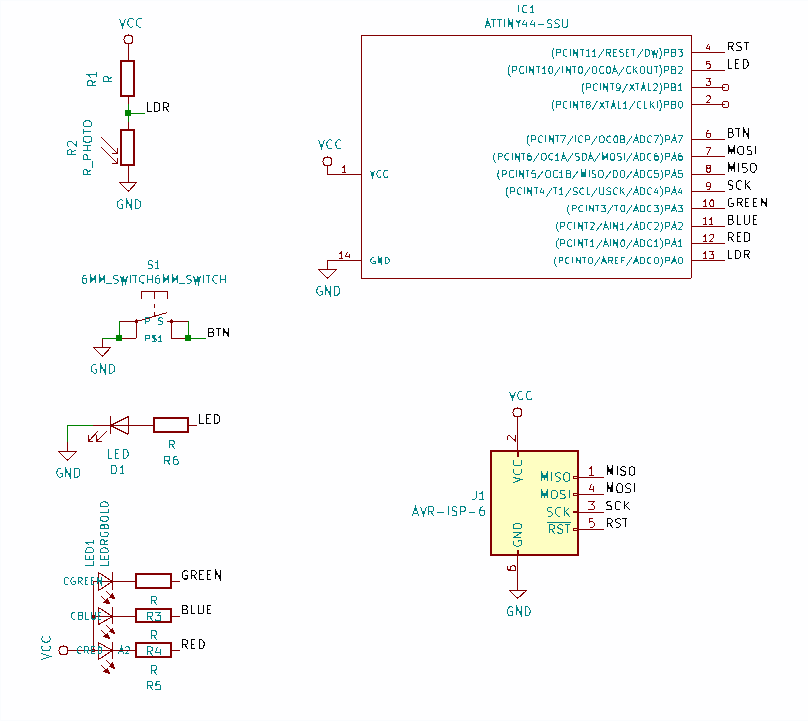
Here I used KiCard and referred to the echo Hello World board by Professor Gershenfeld.
Due to the shortage of electronic materials in the lab, I added other compenents on my PCB. These are components (the RBG LED and LDR) I may need to work with in following assignments.
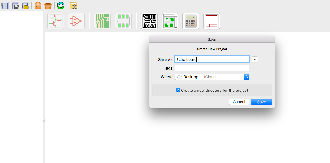
I created a new project that I called echo board
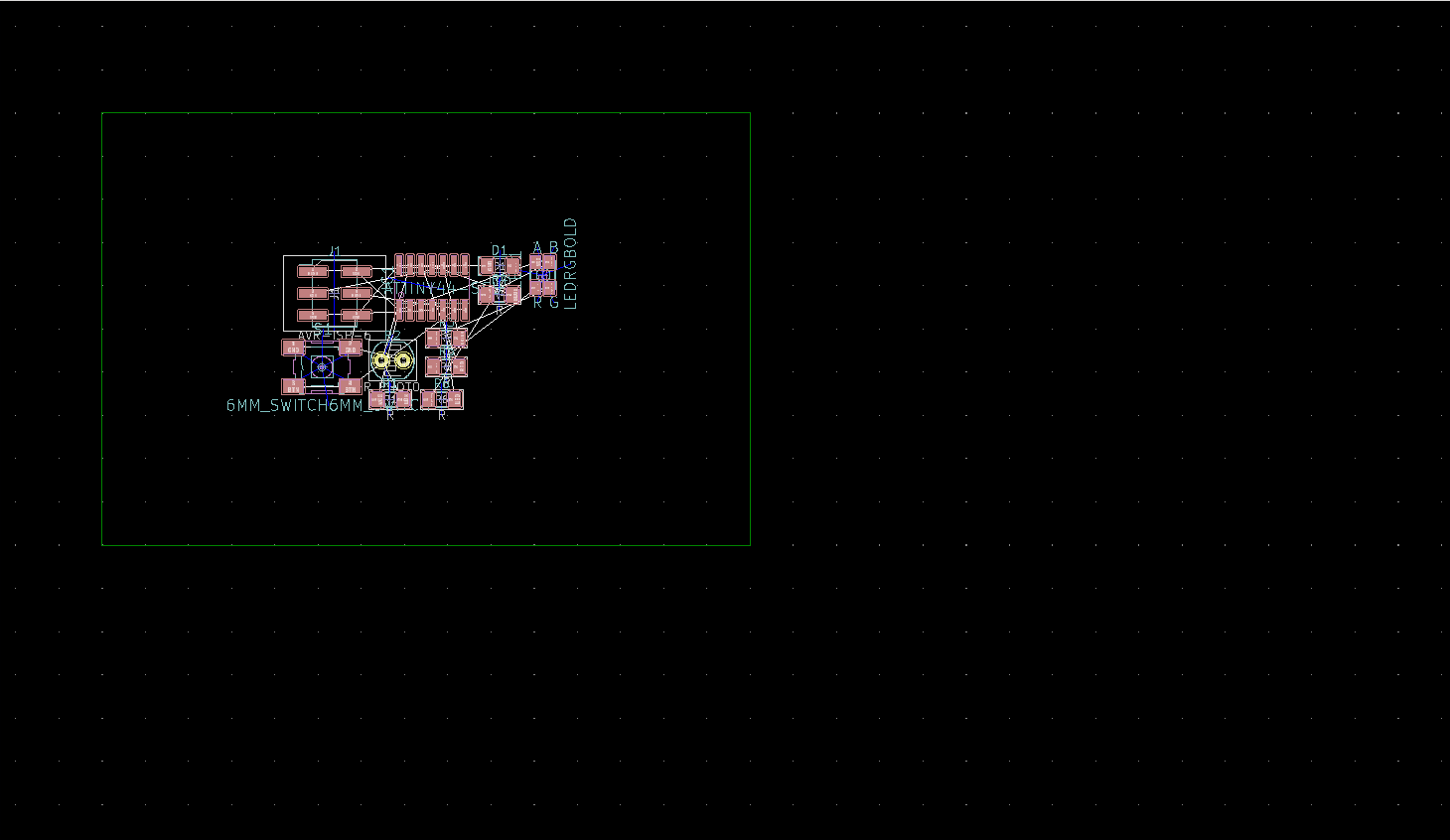
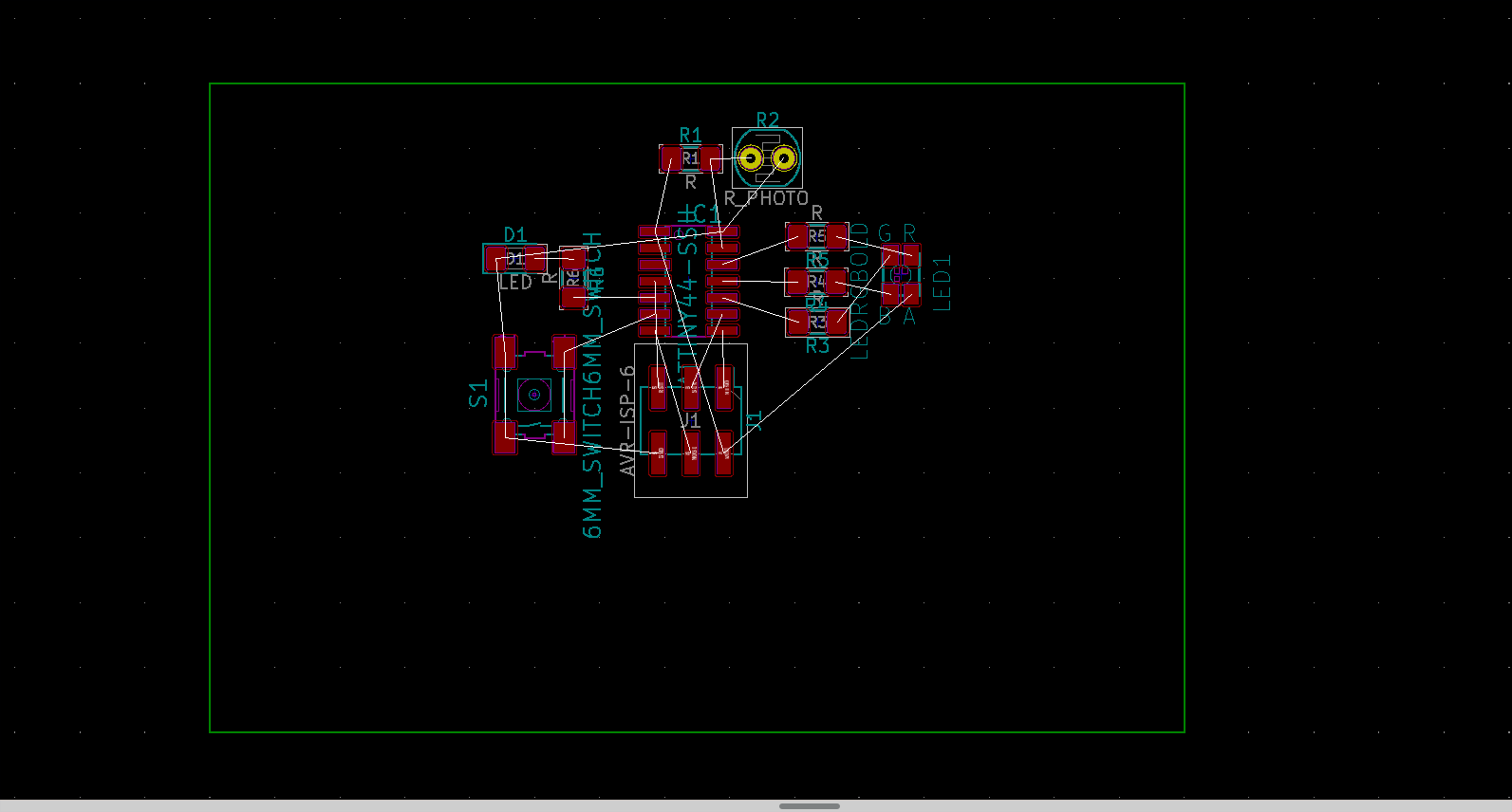
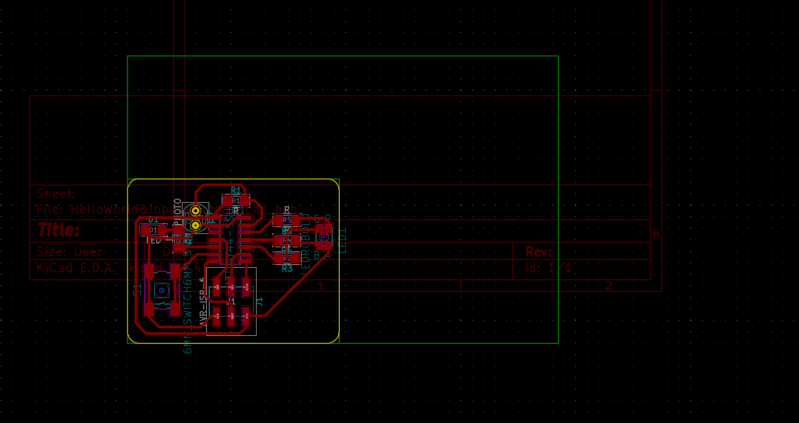
After, I added all components. Once all components are added the screen looks like this:
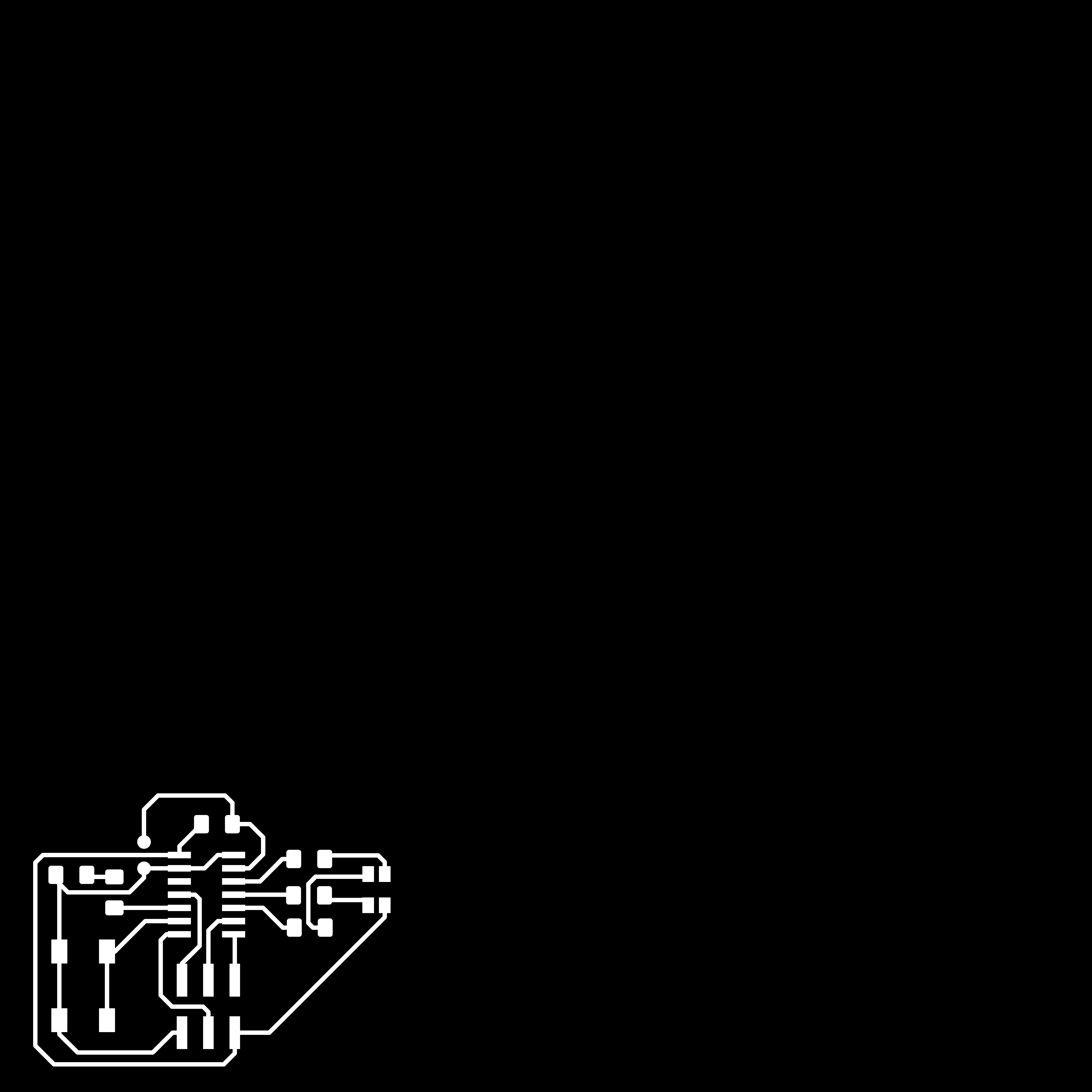
Saving the png file image for the traces:
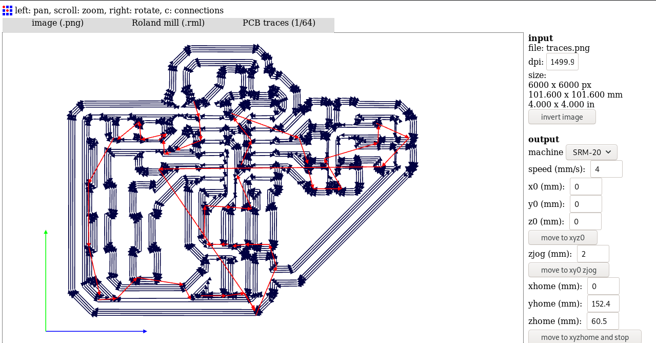
Importing the png image in fabmodules to generate the path and .rml file for the milling machine
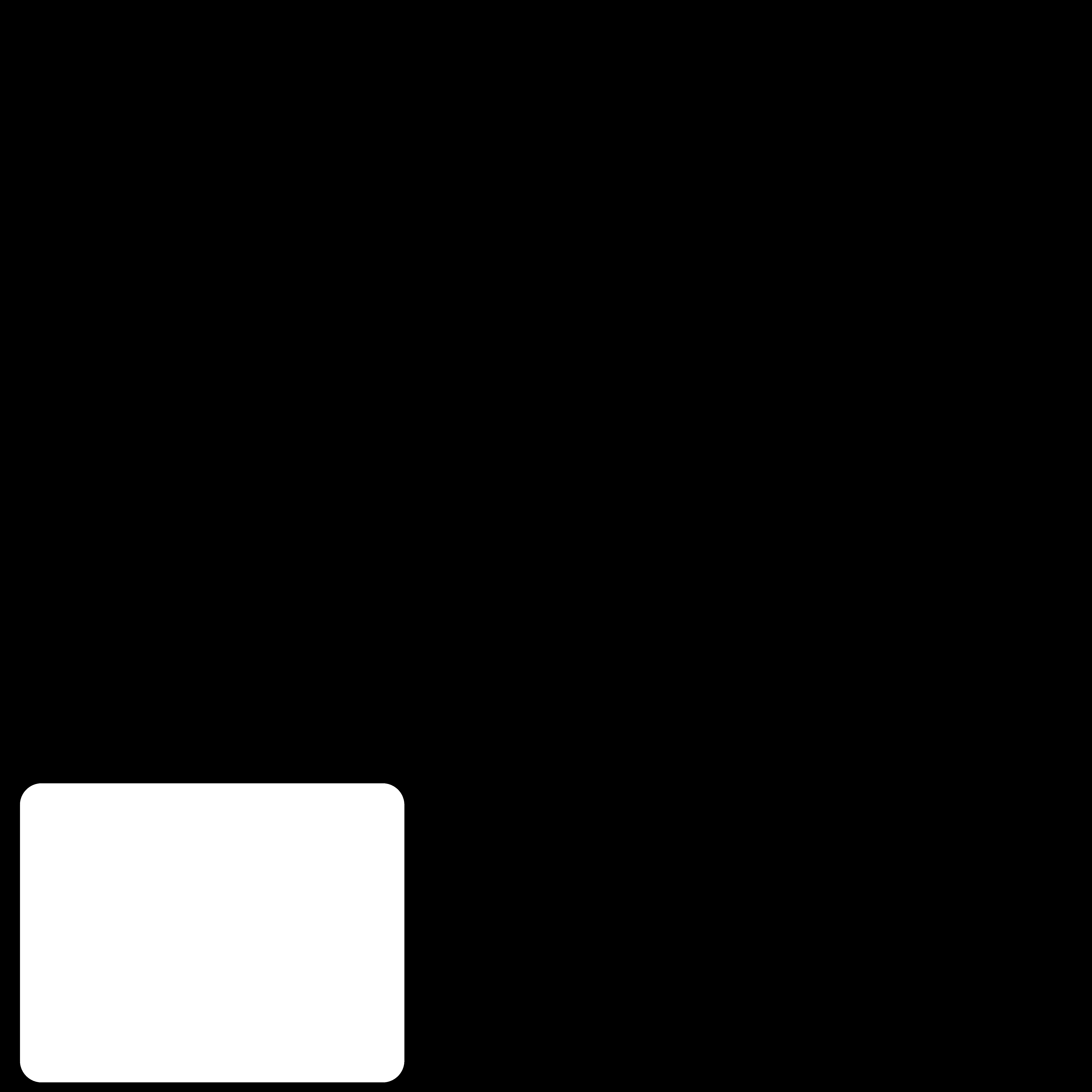
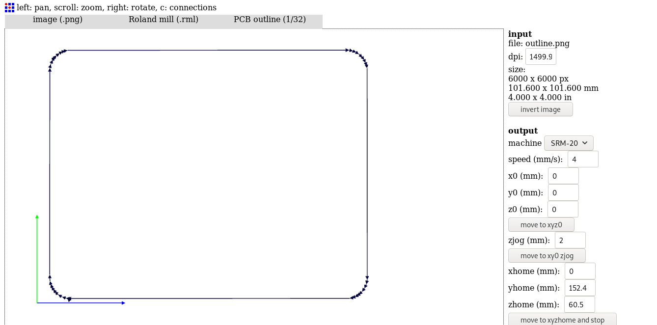
Saving the png file image for the outline:
Importing the png image in fabmodules to generate the path and .rml file for the milling machine
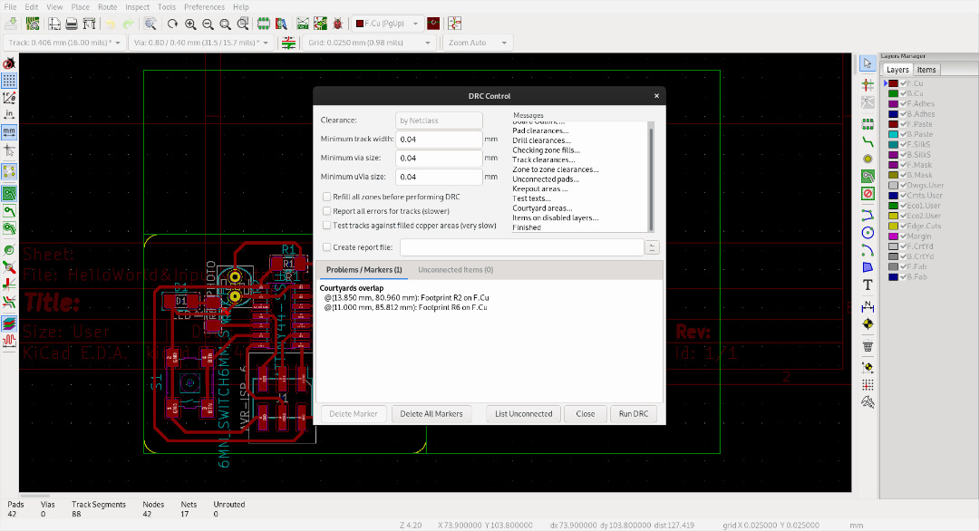
After the above, we need to make sure that the thicknes of the traces and spece between them are the correct ones. To edit so we neeed to go to DRC icon and put 0.04mm everywhere.
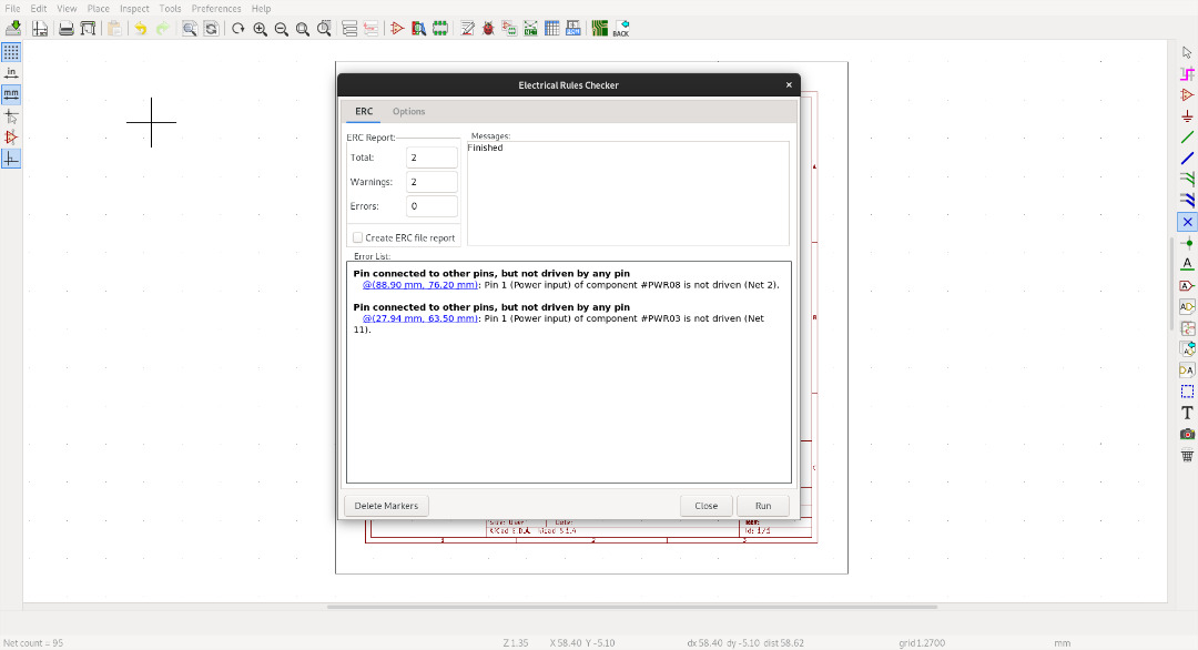
One of the feature in Kicad is to check the schematic for any electrical rule error. So i tested that out after preparing my schematic.
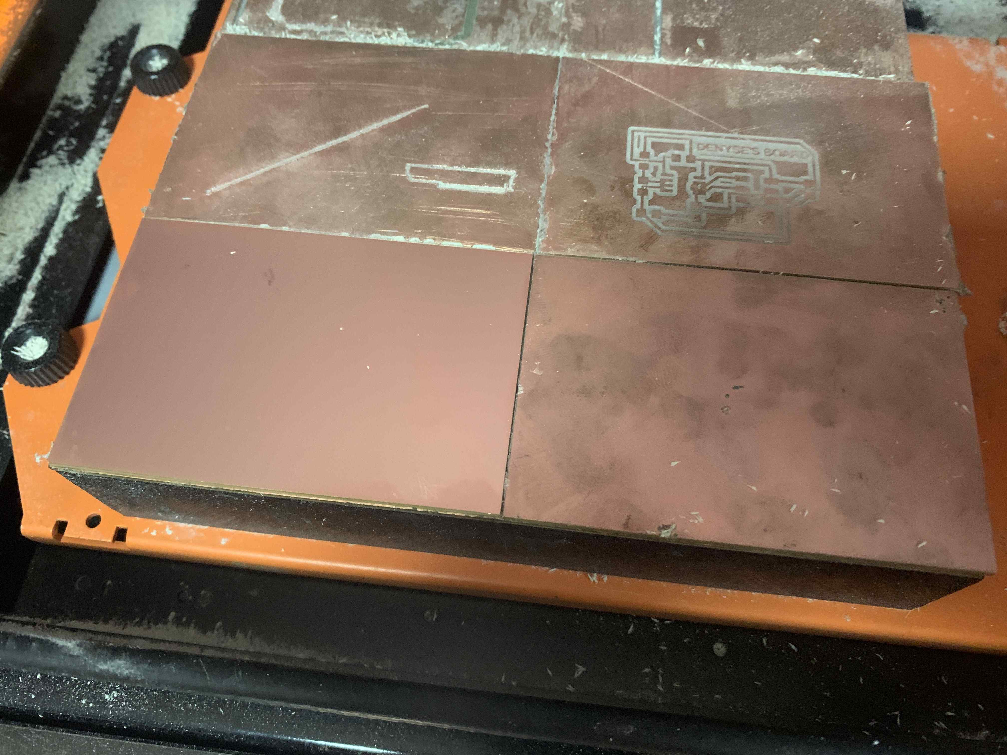
Preparing the bed and fixing the FR4 board with a tape on the sacrificial board
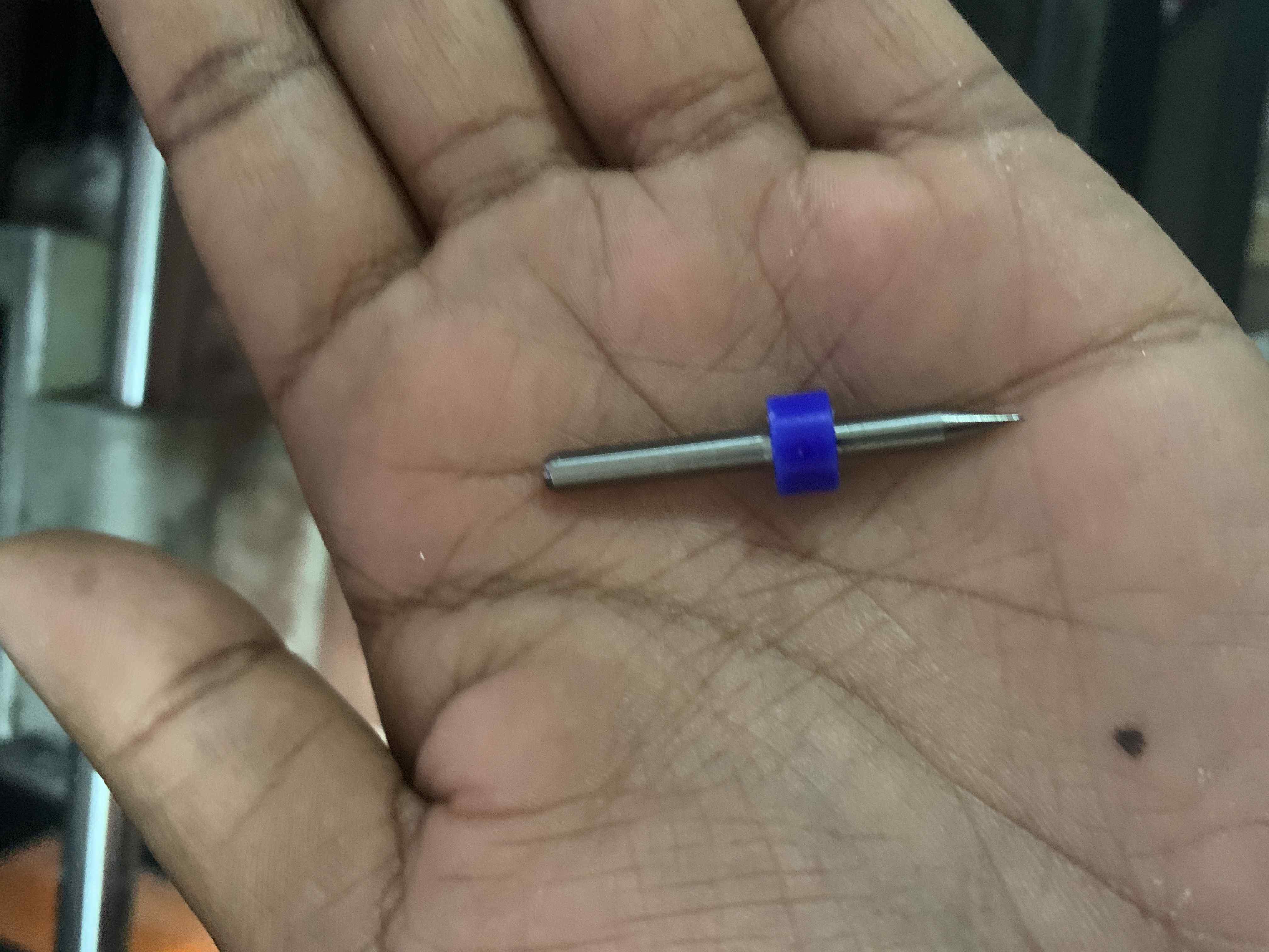
We use this tool to mill the traces on the board.
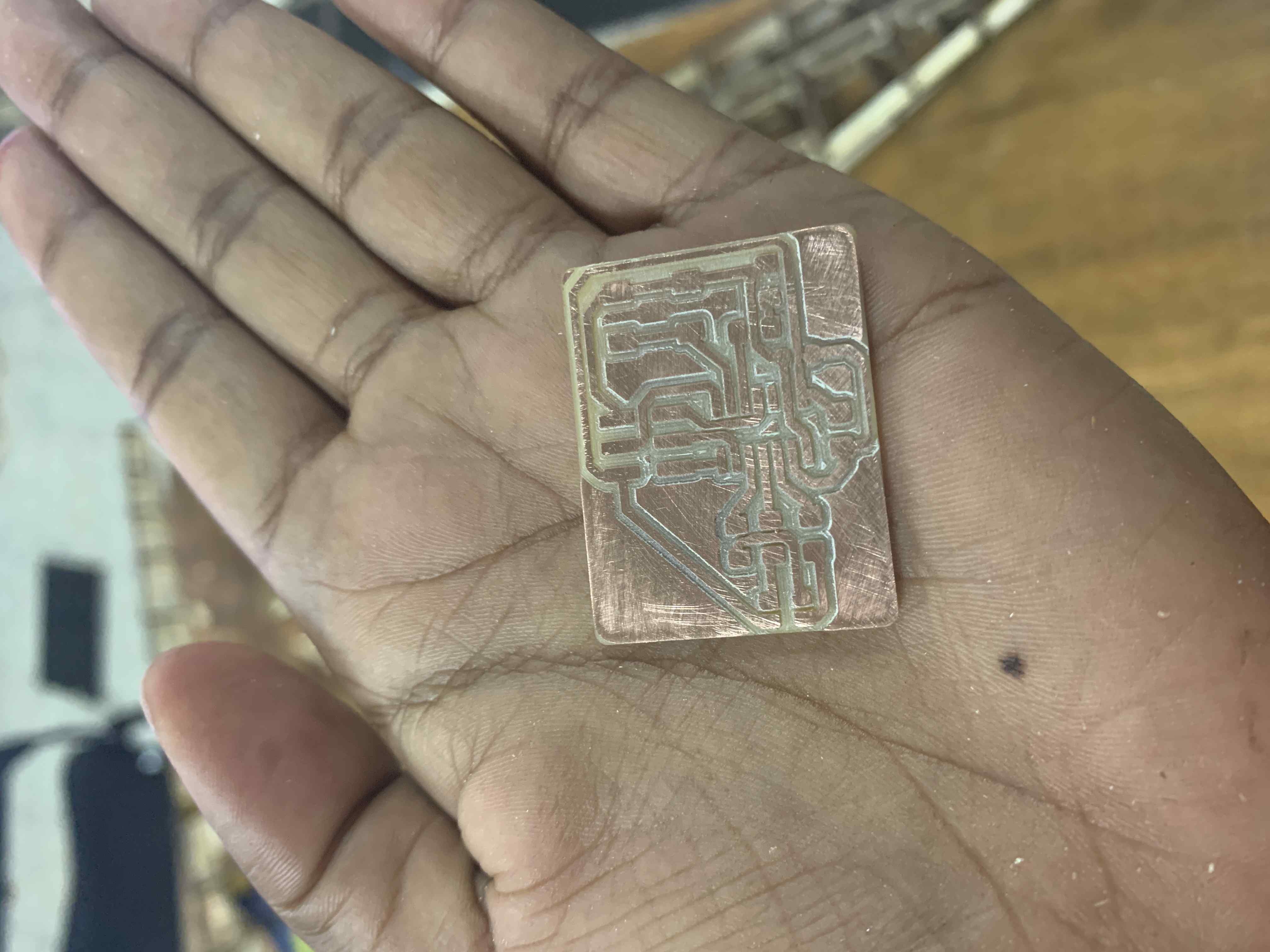
Checking if the traces were done correctly.
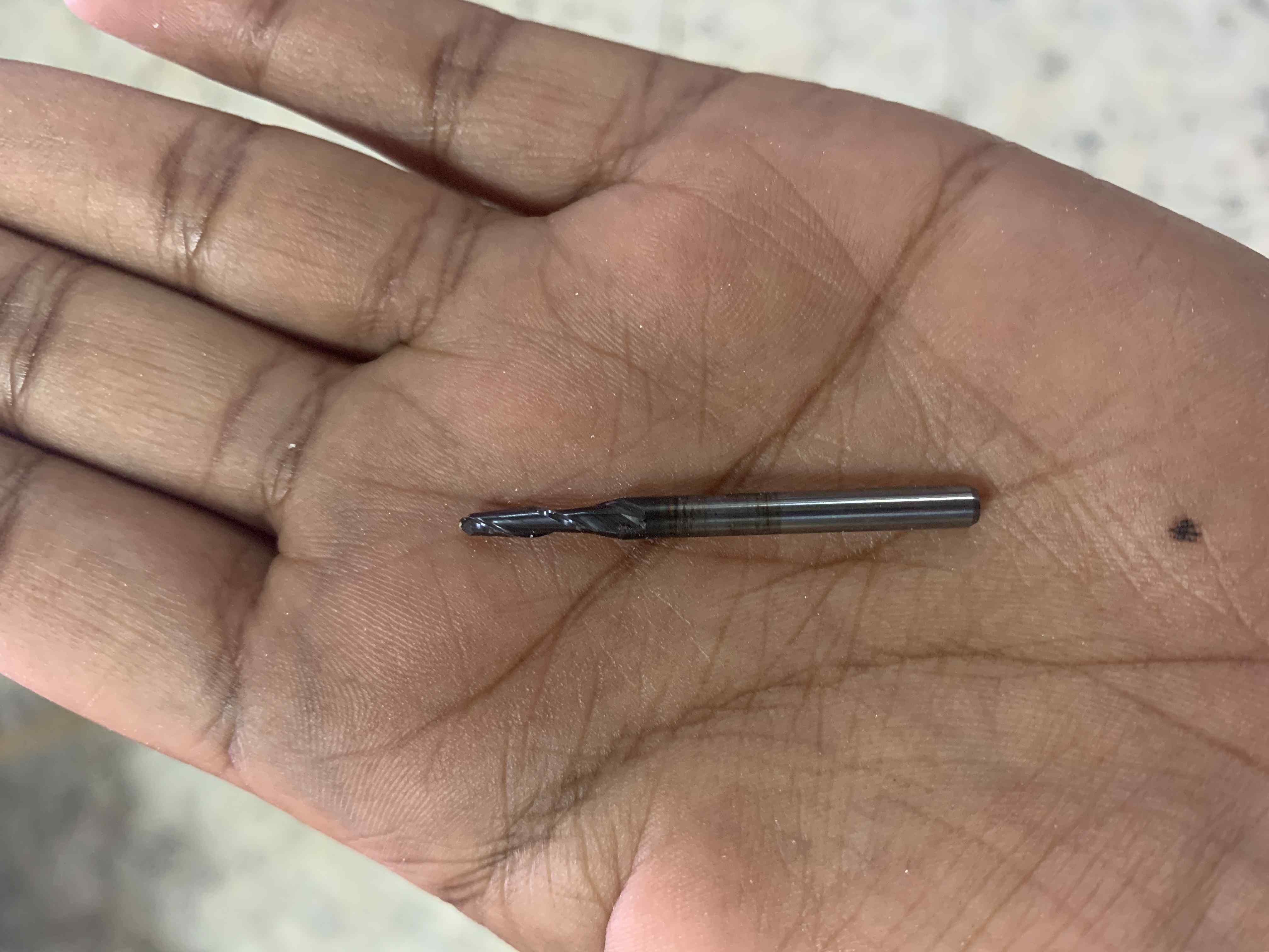
We use this tool for deeper cutting (of the edge).
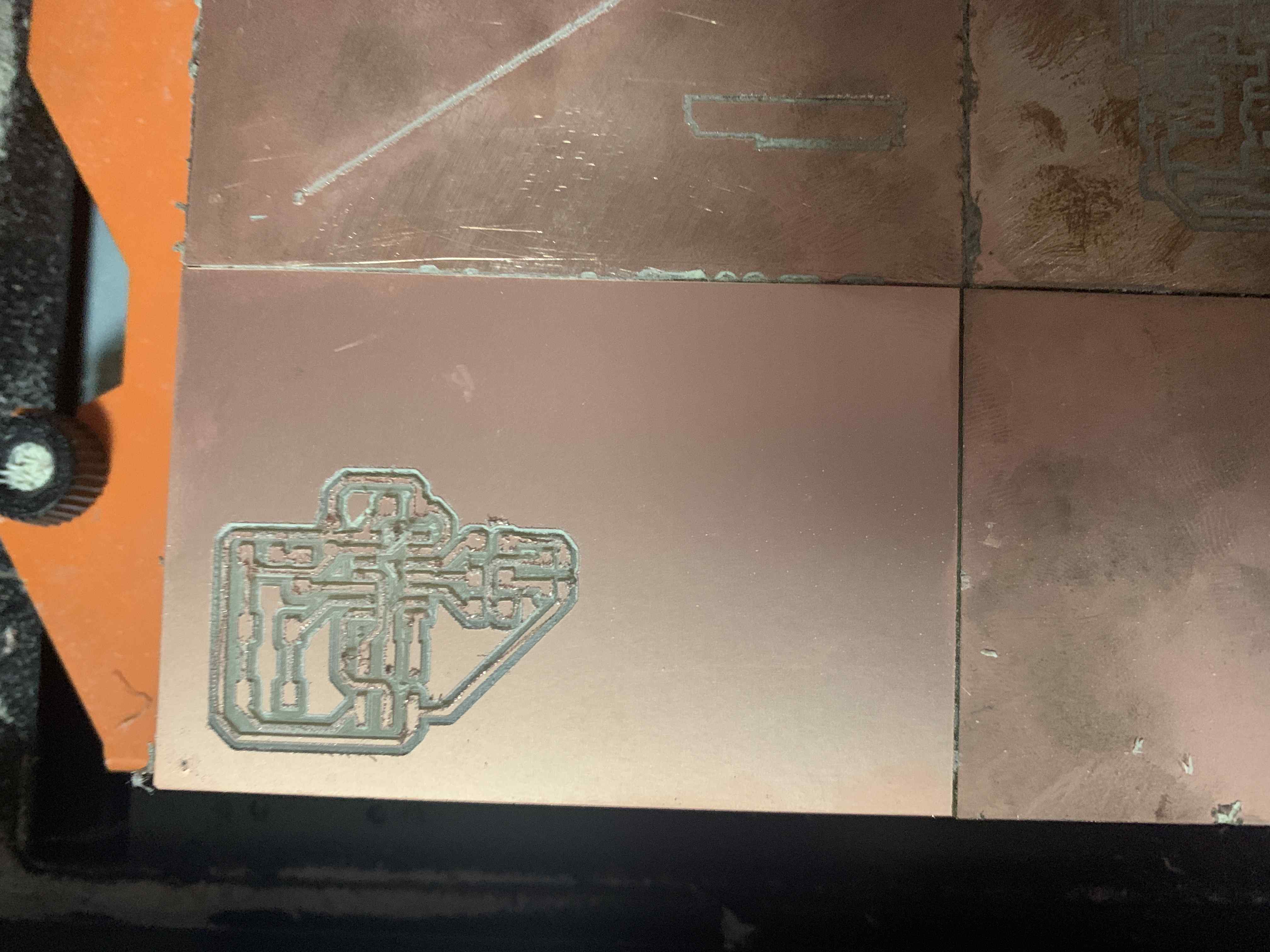
This is how it looked like after milling.
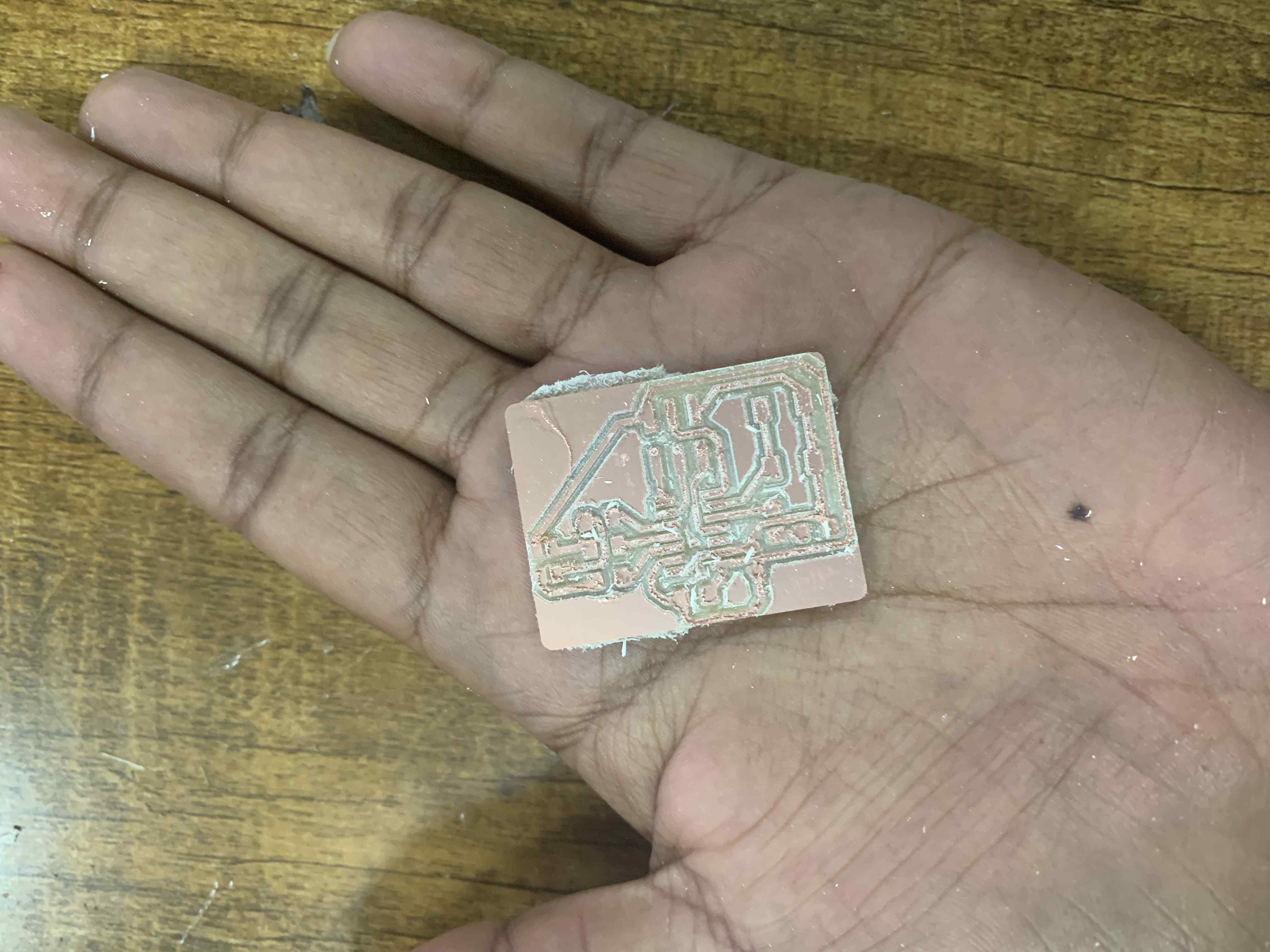
I used that black scratcher to remove the top materials.
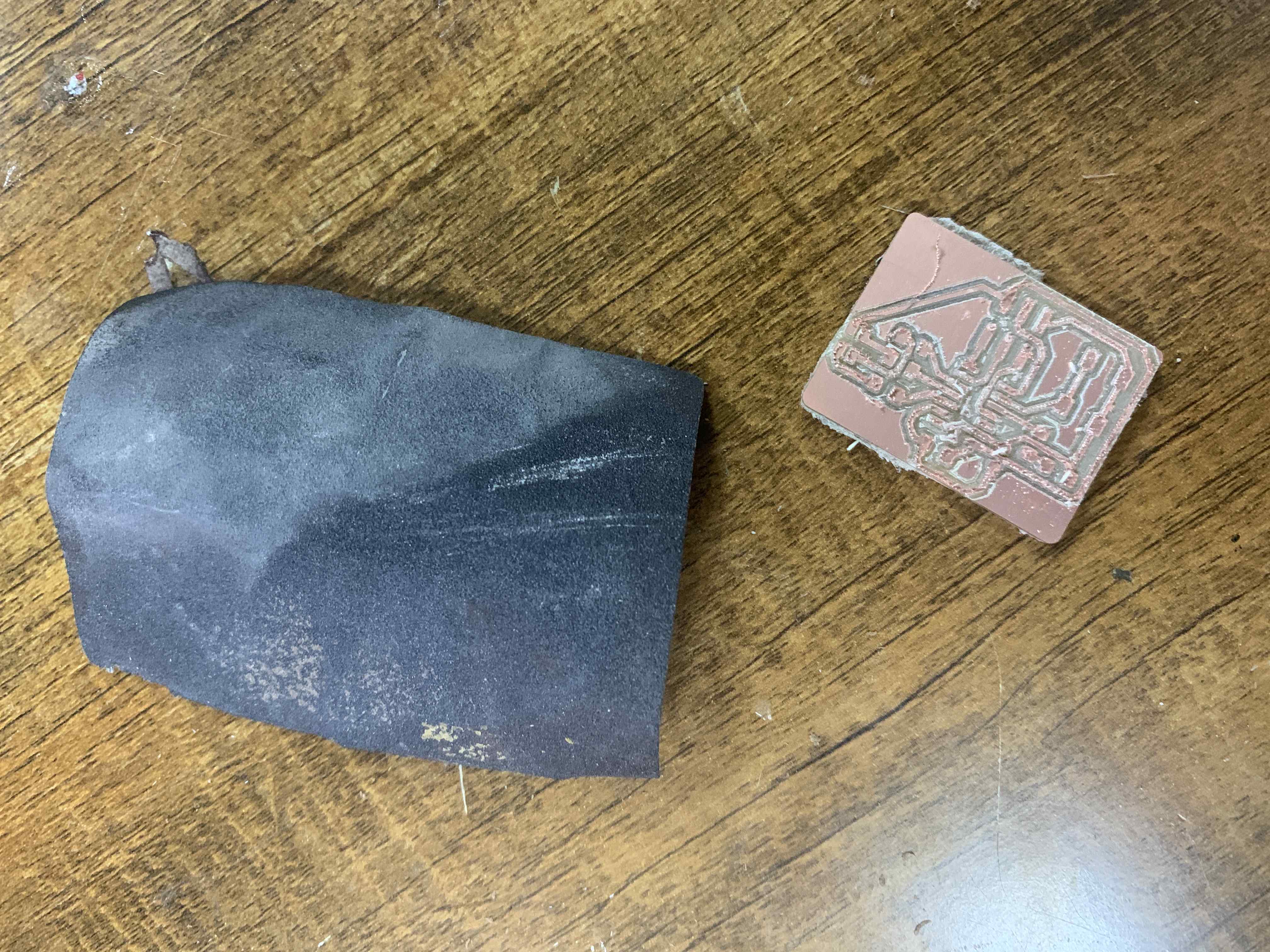
Result
| No | Component |
|---|---|
| 1 | ATtiny44 |
| 2 | LDR |
| 3 | LED |
| 4 | RGB LED |
| 5 | 5 resistors (499 ohm) |
| 6 | Push button |
| 7 | AVR ISP |
Below is how I calculated the resistor for the LED:
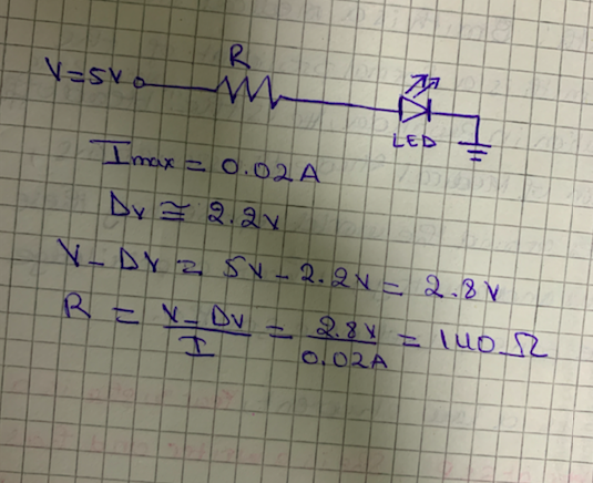
I used 499 ohm resistor because it was the only available in the lab higher than 140 ohm. I avoided to use resistor with less resistance because it could burn the LED.
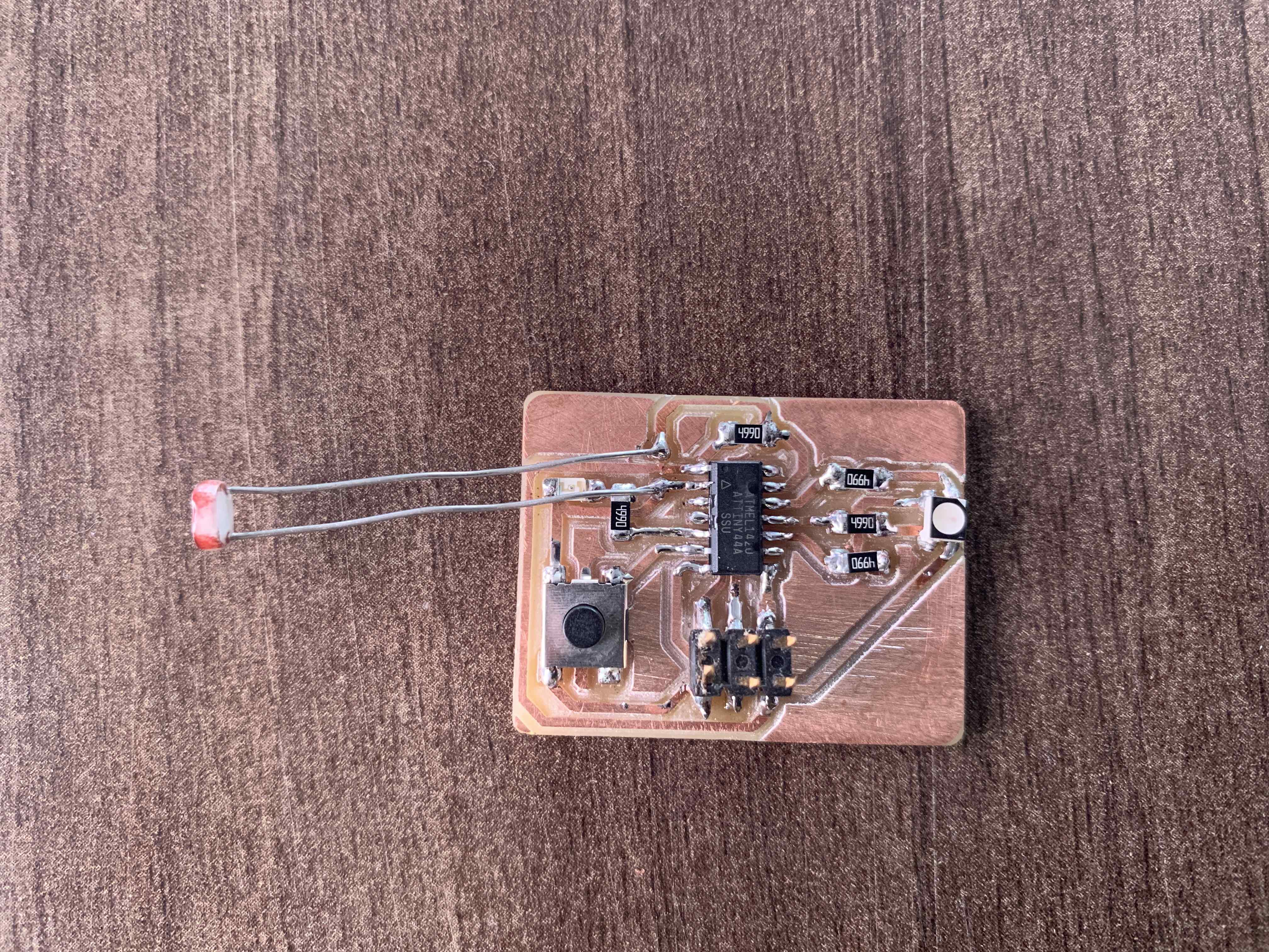
I added the LDR in series with the resistor.
After, I connected the ISP programmer that I made earlier, to the other USB port. Used the ribbon cable to connect the FabISP and the Hello board using the two six-pin headers connected to each other.
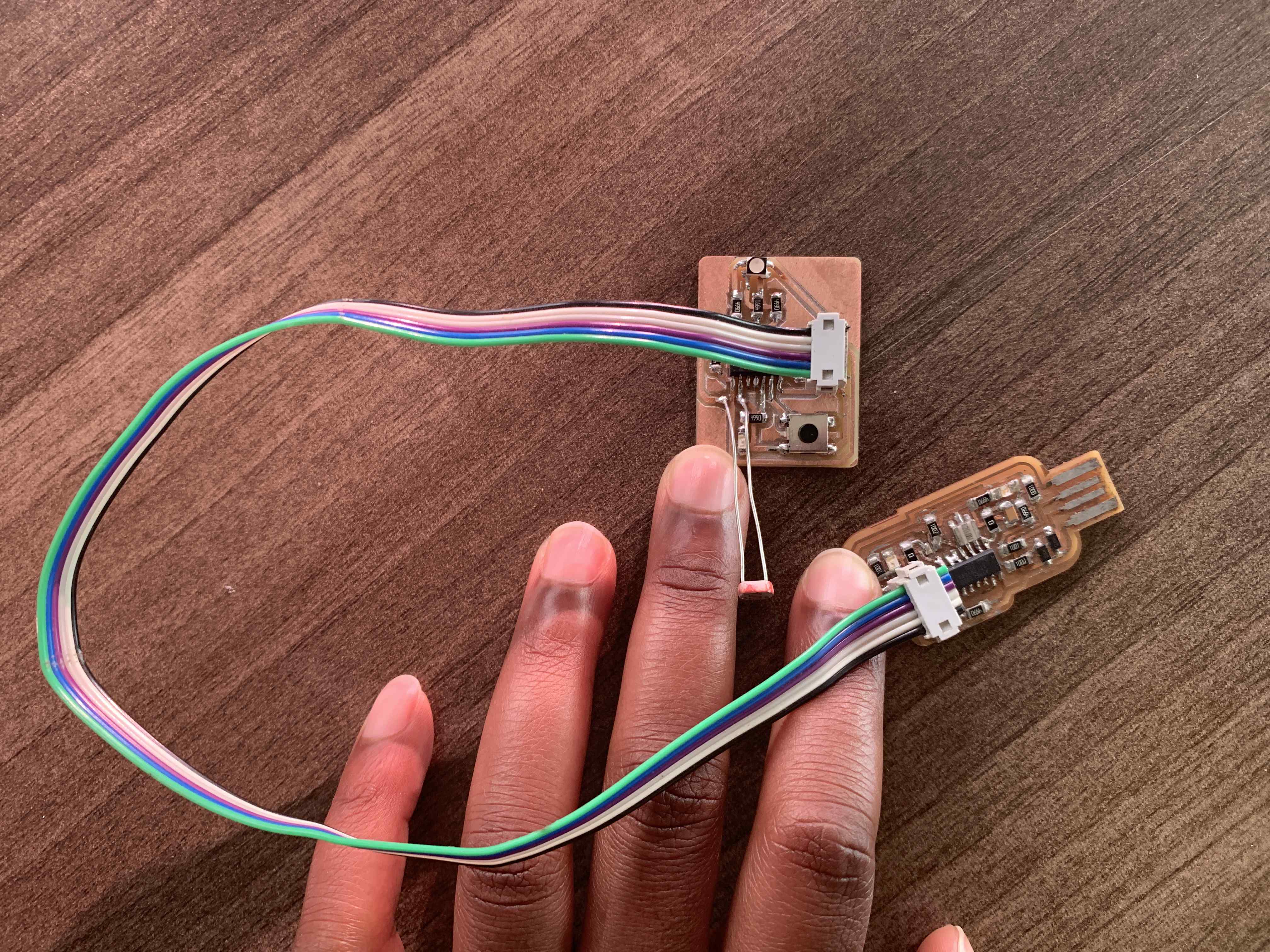
Uploaded the codes:
Receiving input from the push button and lighting the LED:
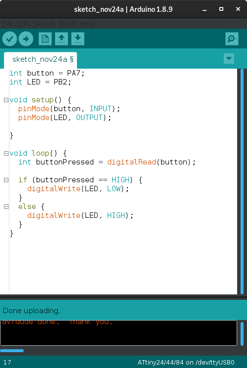
Test :
Files: