Electronics Design
Designing a PCB and milling it!
The individual assignment of this week is to redraw the echo hello-world board, mill it, and add, at least, a button and LED. First thing I did was to draw the schematics of the board on Eagle and convert them to a board.
.png)
First, I added the components:
6-pin programming header
microcontroller
FTDI header
20MHz resonator
Resistor (10k and 499 ohms)
Button
Ground
VCC
LED (Light Emitting Diode)
.png)
I connected the components.
.png)
and added their names and values.
.png)
The next step was to switch to board (from the File menu).
.png)
and re-connect the components.
.png)
Re-connecting took a lot of time, but it eventually worked out.
.png)
Almost done.
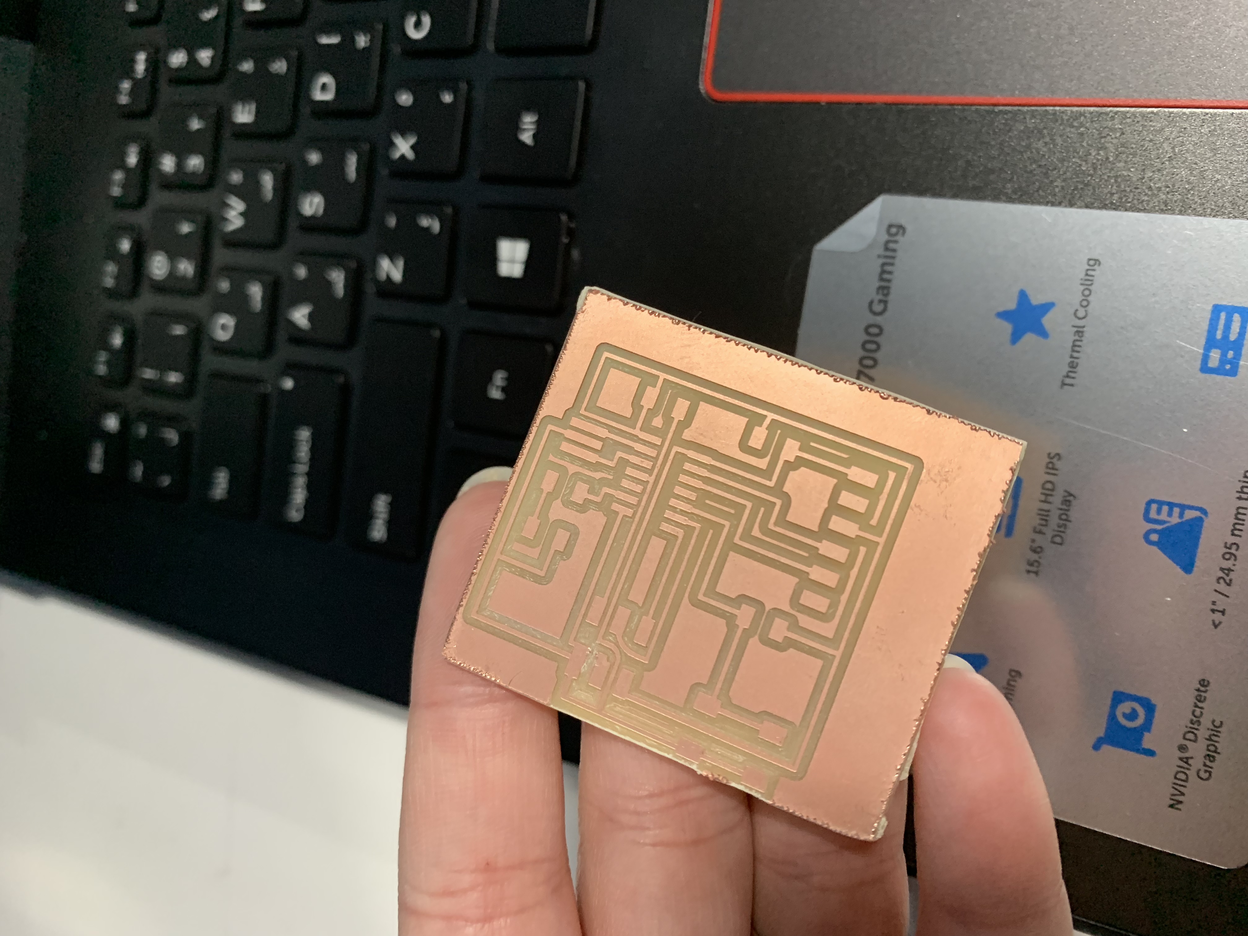
The next step was to mill the boeard and prepare it for soldering of the componenets:
- 1 x Attiny44A
- 2 x 10K resistors
- 1 x 499 resistor
- 1 x uf Capacitor
- 1 x LED
- 1 x 6 pin header
- 1 x FTDI header
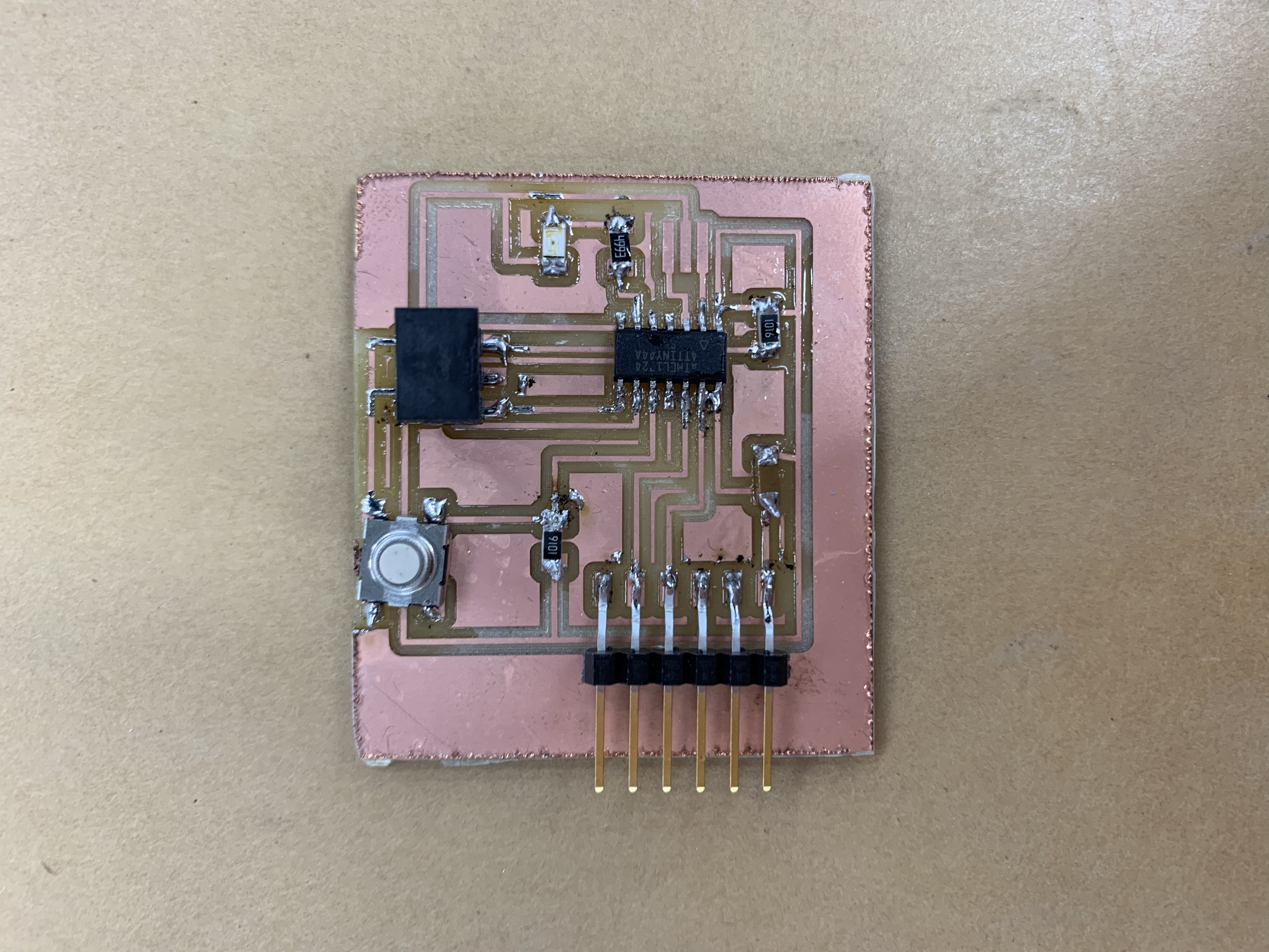
and this is the final board, soldered:
Files
Outline.RMLTraces.RML