Electronics Production
Milling, Soldering, and Programming
This week's assignment was to mill and solder a FabTinyISP and a Fab ISP. I strated with the FabTiny ISP using the following files:
The above file was for the traces of the board, which we cut first. I uploaded it to Fabmodules.org to convert it into an RML file, compatible with the Roland MDX-50 machine I'll be using for milling.
On Fab Modules, I used the following specifications:
Input Format - PNG - I picked my file
Output Format - RML
Process - PCB Traces (1/64)
In the process settings, I input the following:
Maching MDX-40
Speed: 2
x0:0
y0:0
z0:0
zjog:2
xhome:0
yhome:0
zhome:2
depth:0.2 mm
tool diameter: 0.4
number of offsets:4
Calculate and save.
I got my first RML file!
The next step was to create the RML file of the outline using this file:

I uploaded it to Fabmodules.org as an input.
The output format is RML again, and the process is PCB Outline (1/32)
In the process settings, I input the following:
Maching MDX-40
Speed: 2
x0:0
y0:0
z0:0
zjog:2
xhome:0
yhome:0
zhome:2
Cut depth: 1.76
Stock thickness: 1.6
number of offsets:1
Calculate and save.
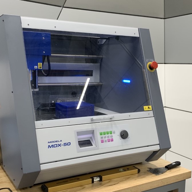
Then, I took the output .RML files to VPanel, the software connected to the Roland MDX-50 (pictured below).
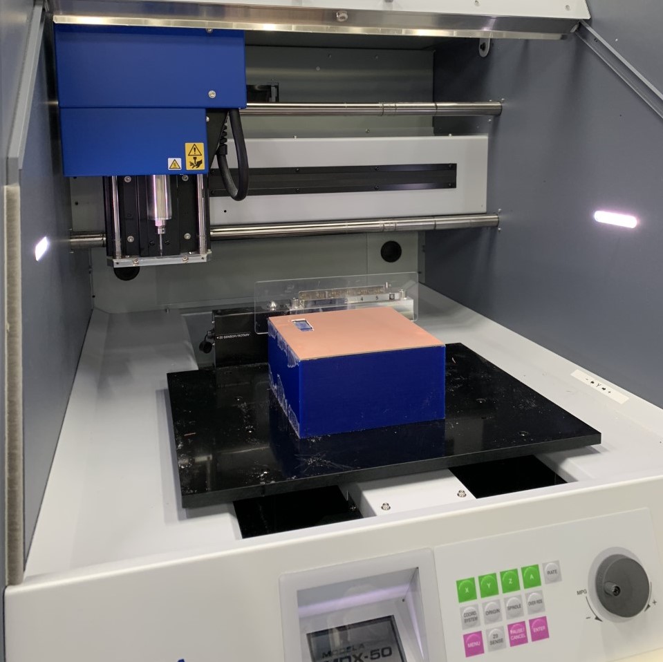
Using double-faced tape, I place the copper board to the wax, preparing it for milling.
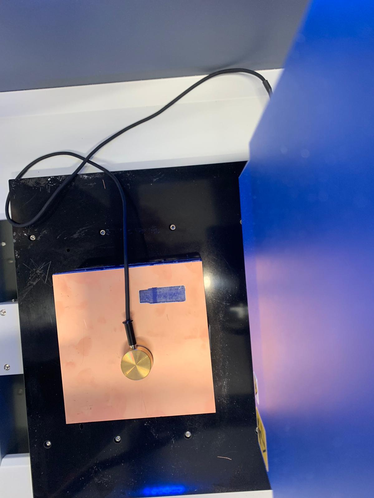
I sat the Z0 of the board to inform the machine of the actual height of the boeard and the wax.
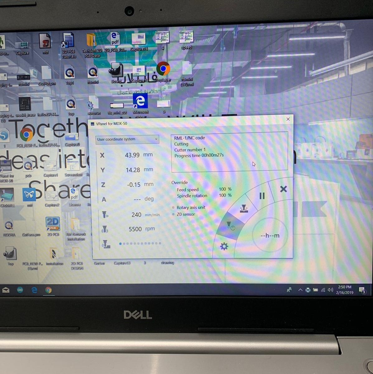
Using the Vpanel dashboard, I sat the x,y and z origins (I found out later that this could've been done on the mashine's dashboard) and uploaded the traces .RML file.
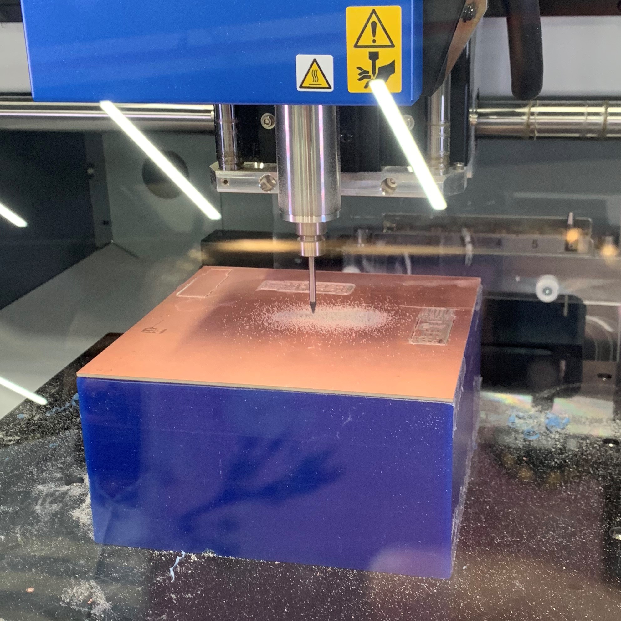
The machine begins working and the resulting board is below.
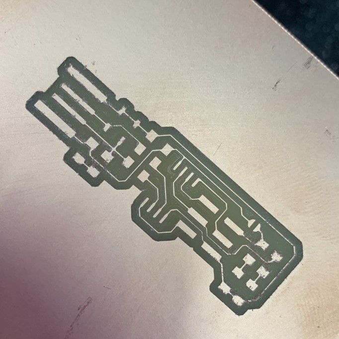
Now that I made sure all inputs are working, I uploaded the outline .RML file and placed the board exactly as it was.
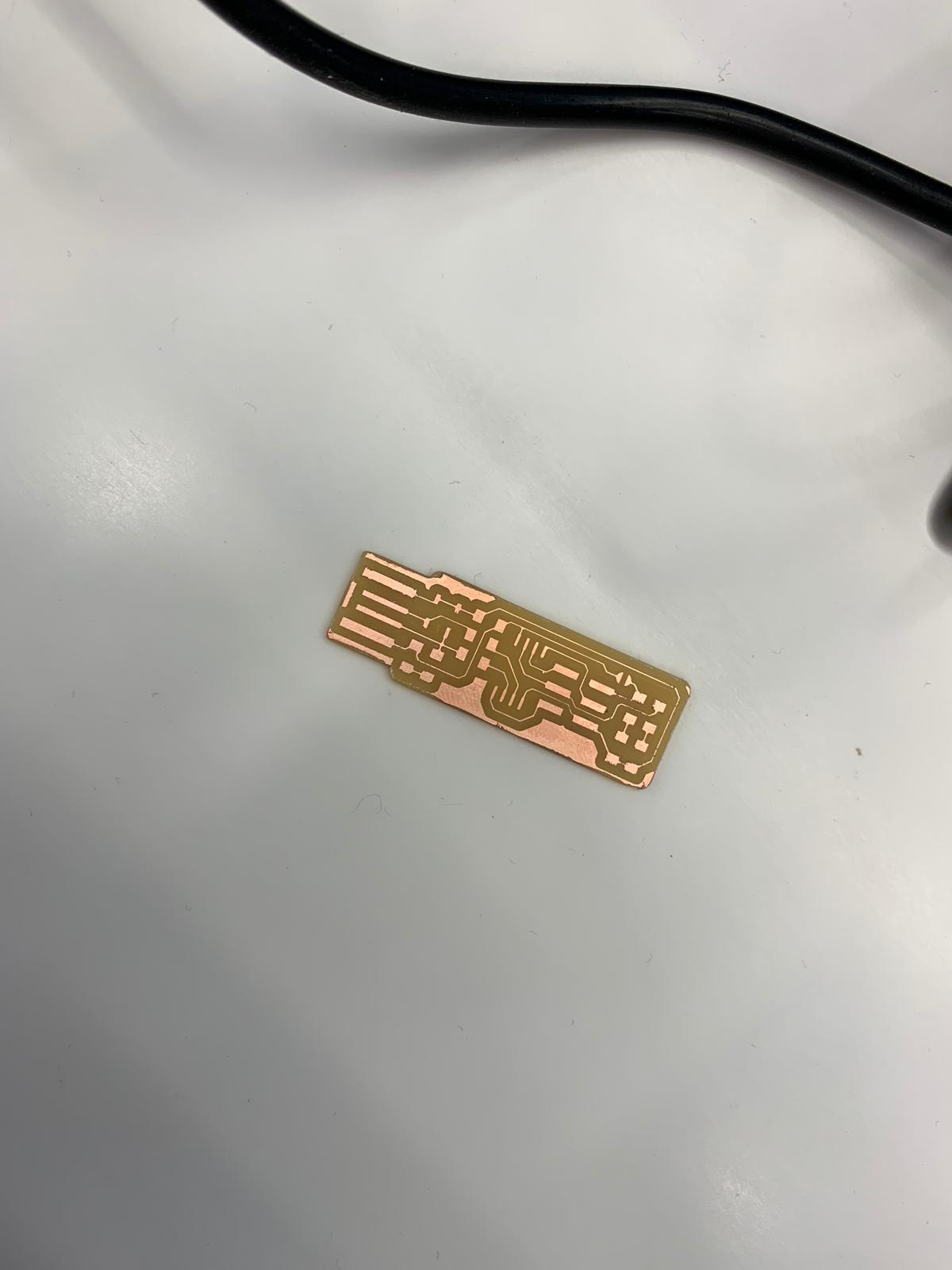
Above is the result of the milling.
The next step is soldering at the soldering station:
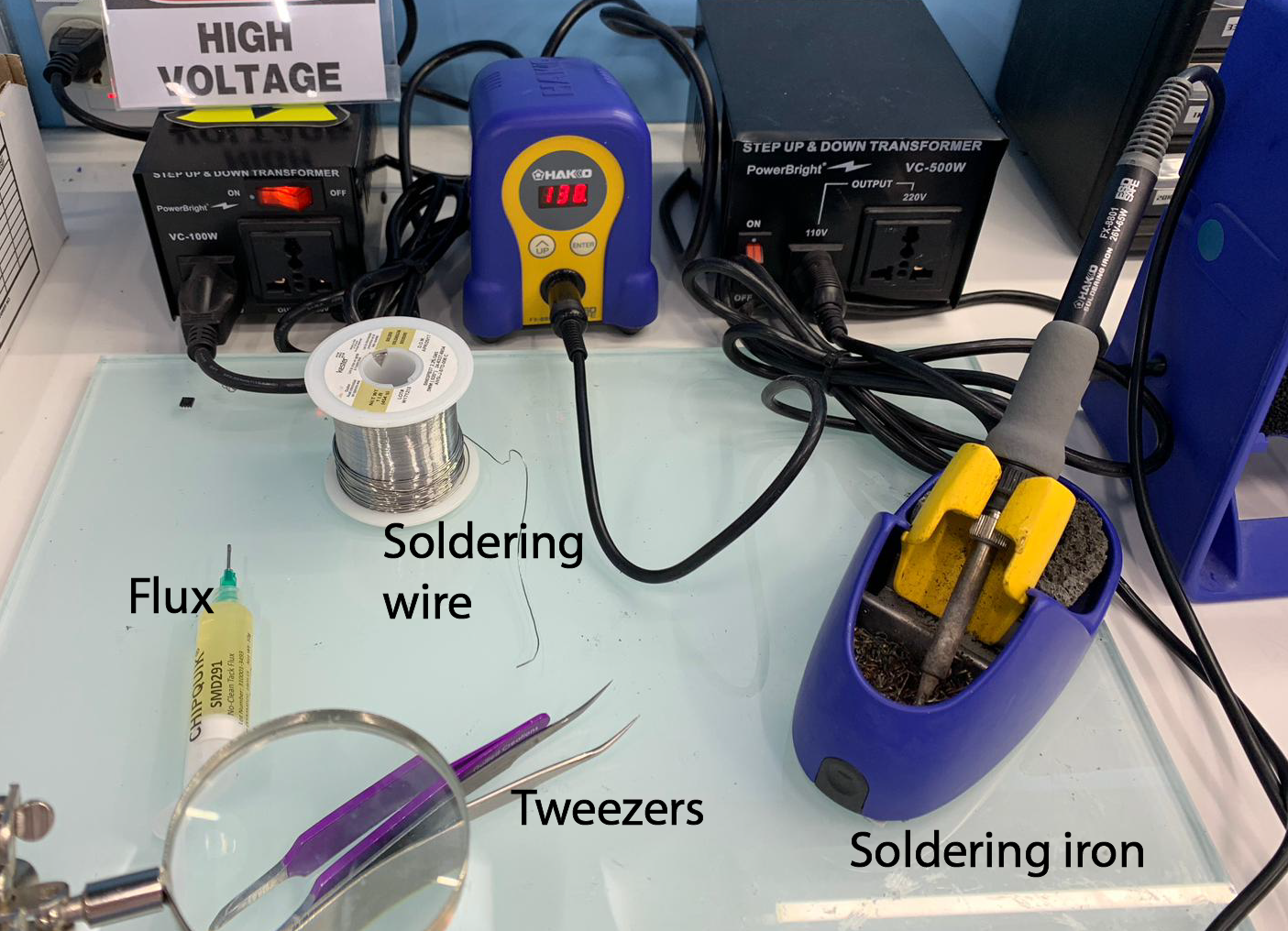
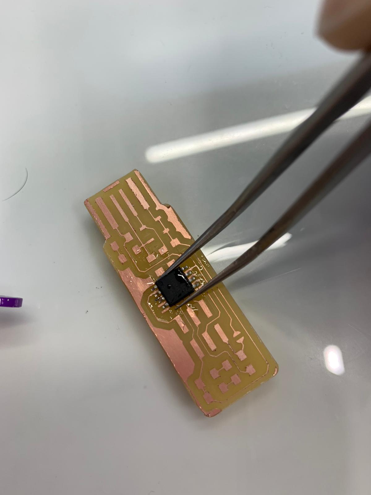
Using the tweezers, I hold the the components onto the board and apply the flus to them. Afterwards, I heat the soldering wire using the soldering iron and paste the molten solder on the sides of the components.
Almost halfway through.
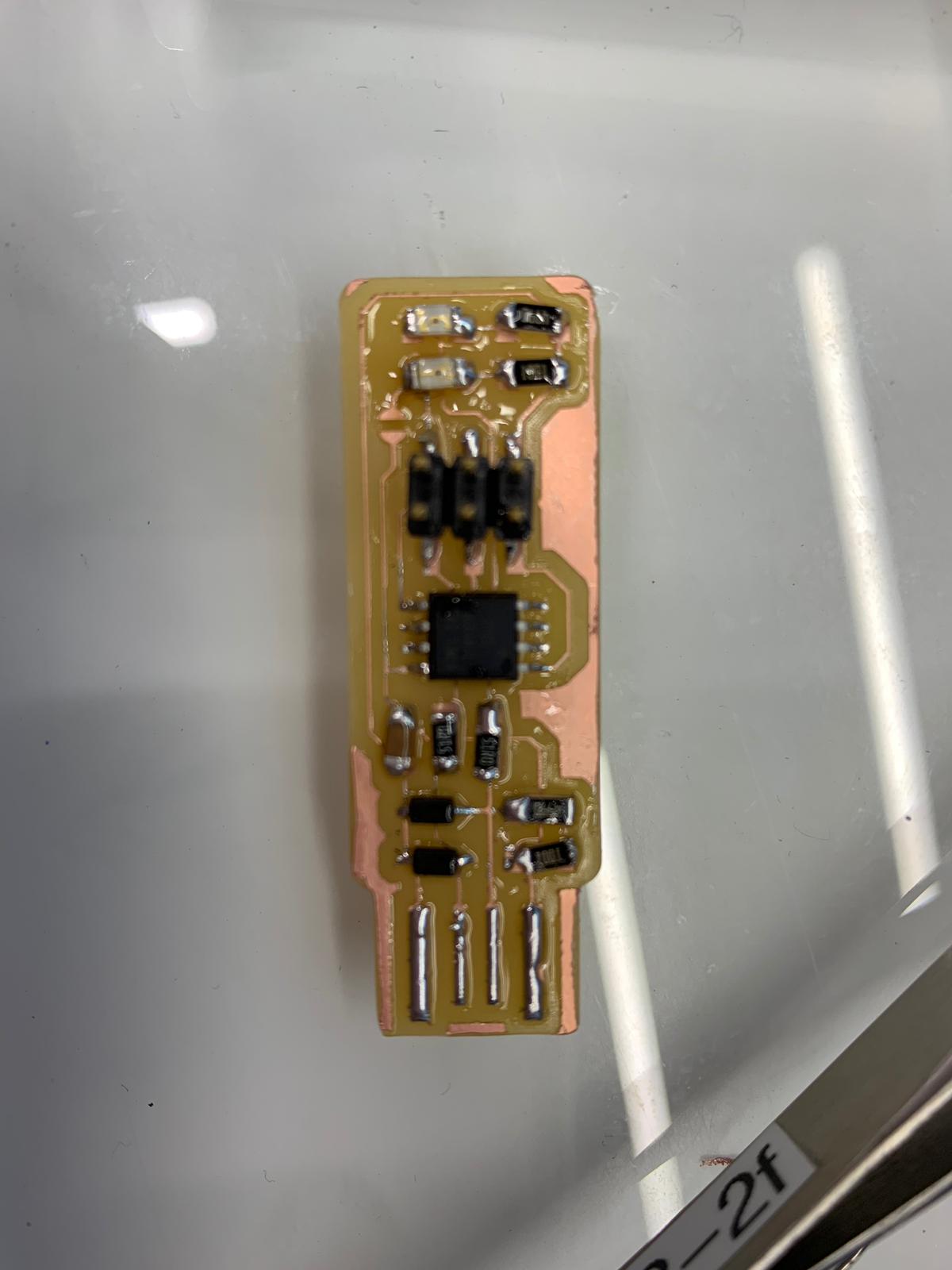
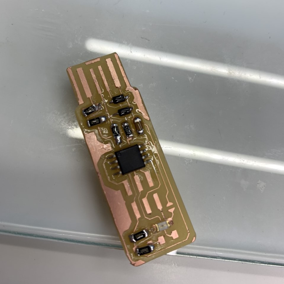
The final board with all components:
1 ATtiny45
2 1kΩ resistors
2 499Ω resistors
2 49Ω resistors
2 3.3v zener diodes
1 red LED
1 green LED
1 100nF capacitor
1 2x3 pin header
To test it, I connected it to a computer. The lit Red LED proves that the circuit is running.
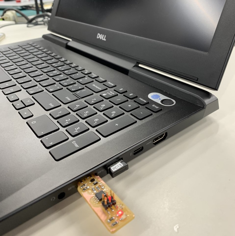
A proud moment as you can all imagine!
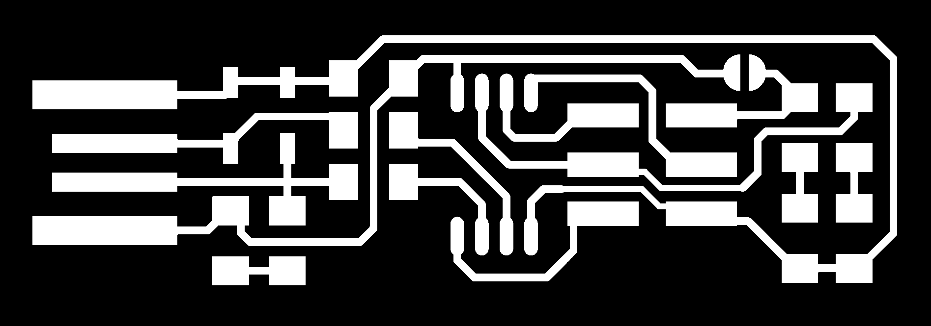
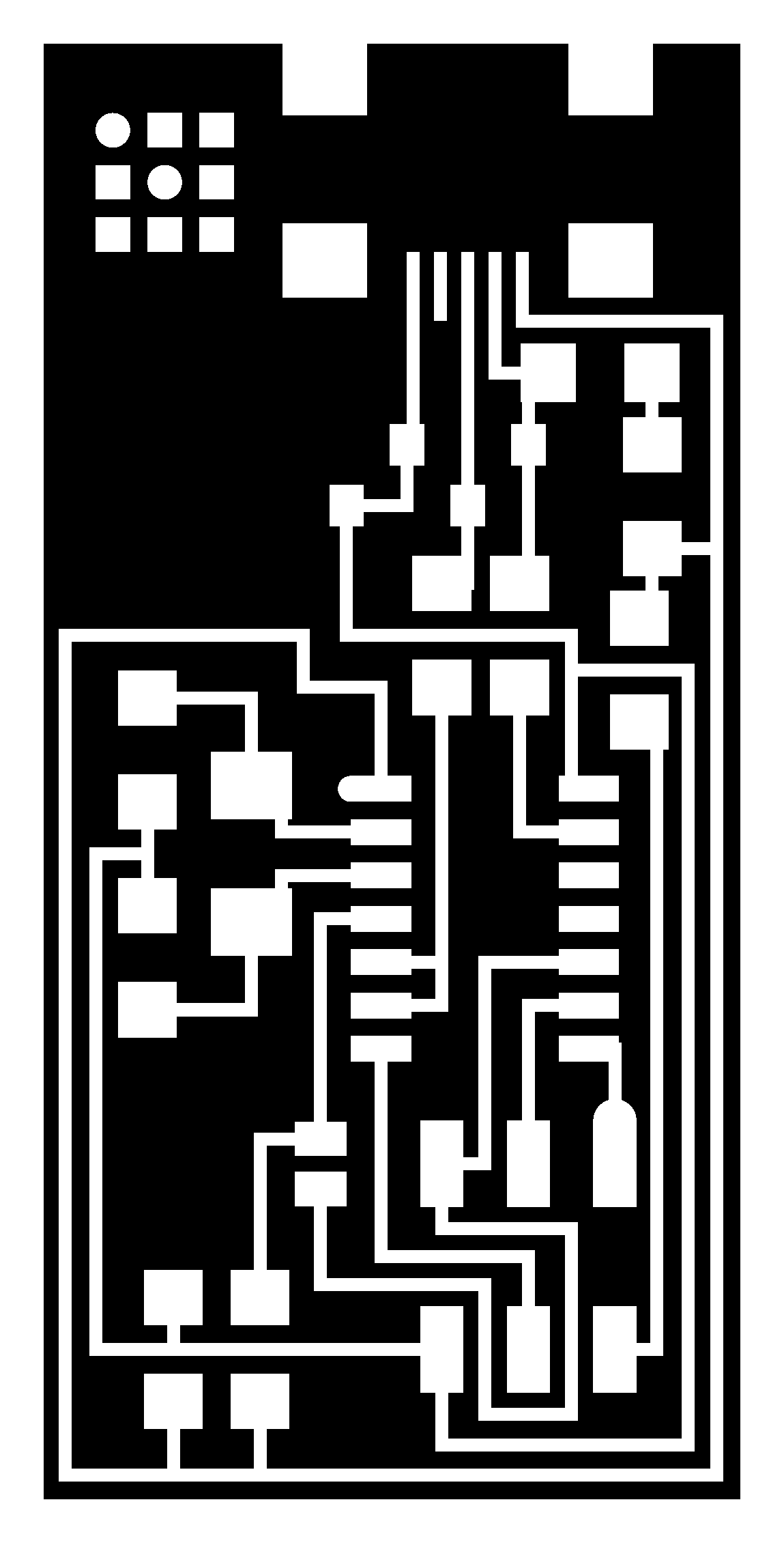
The next step is the Fab ISP, which was easier to make since all difficulties were already experienced during the production of the first board. I used this file for the traces:
This file was used for the outline:

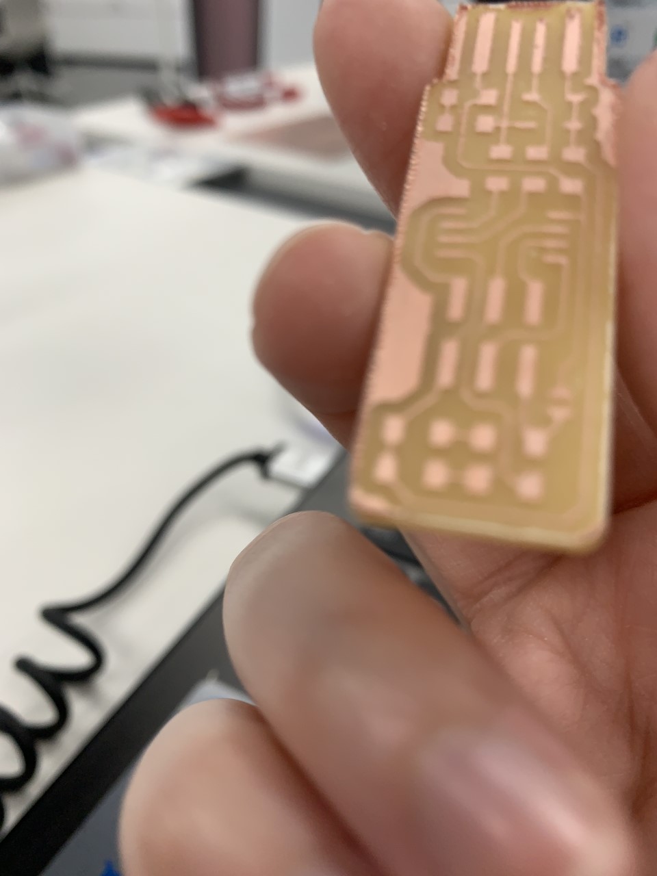
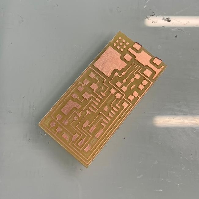
Using the same process, this is how the board looked like after milling:
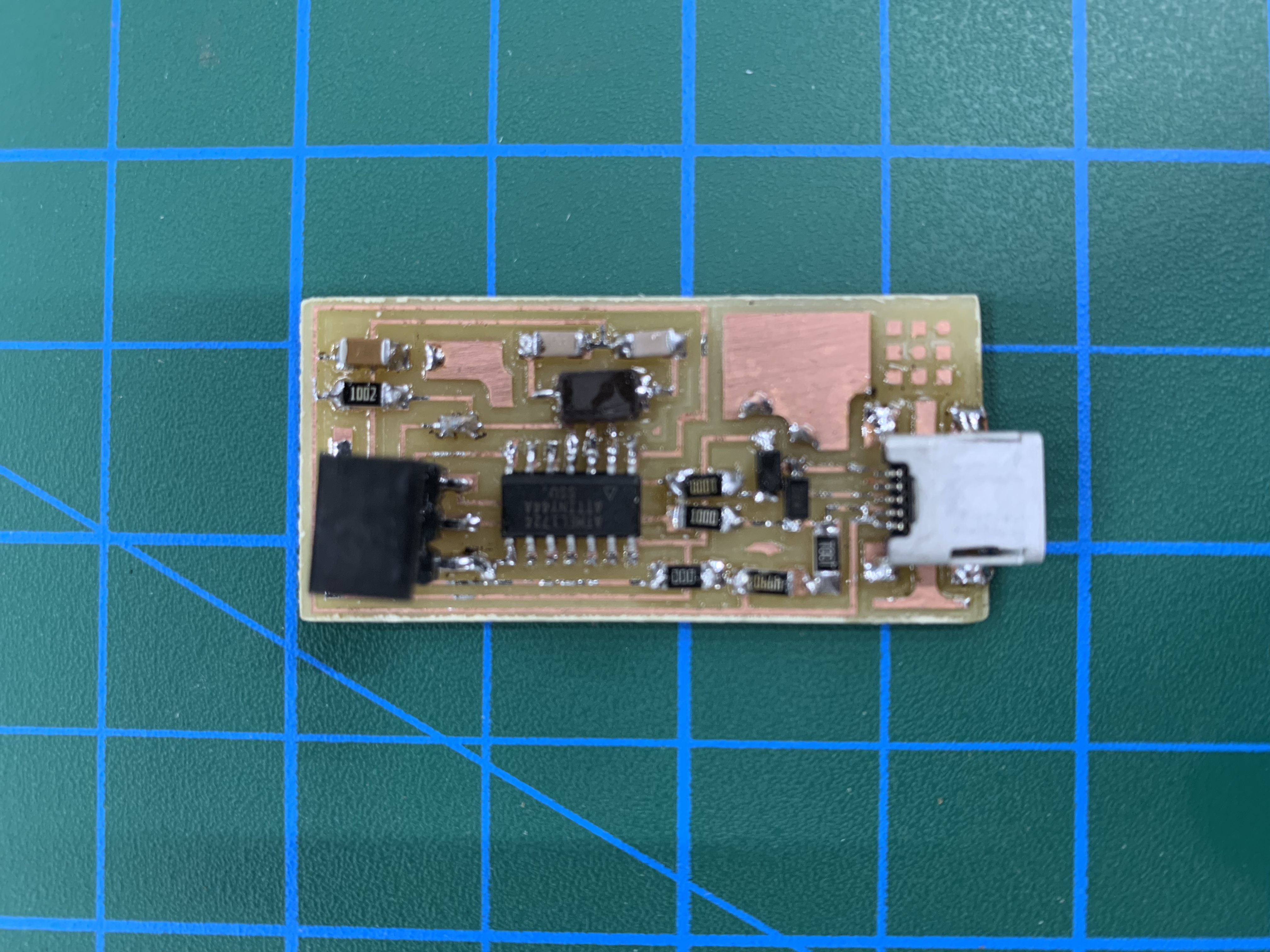
Next is soldering, I soldered all the components:
1 ATTiny 44 microcontroller
1 Capacitor 1uF
2 Capacitor 10 pF
2 Resistor 100 ohm
1 Resistor 499 ohm
1 Resistor 1K ohm
1 Resistor 10K
1 6 pin header
1 USB connector
2 jumpers - 0 ohm resistors
1 Crystal 20MHz
2 Zener Diode 3.3 V
1 usb mini cable
1 ribbon cable
2 6 pin connectors
and this is how it looked after soldering:
Files:
FabTinyISP Outline.RML
FabTinyISP Traces.RML
Fab ISP Outline.RML
Fab ISP Traces.RML
Copyright © Reeman Bustami 2019