The router //
This week we learned about computer controlled machining, which is a machine that allows us to cut some materials, in this case 15 mm wood.
This week we learned about computer controlled machining, which is a machine that allows us to cut some materials, in this case 15 mm wood.
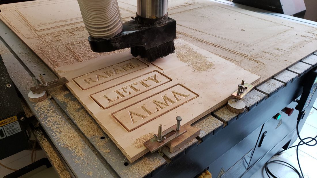
For the team practice that consisted in characterizing the machine we had, we decided to make a test of engraving and cutting, our names on a plate created directly from the software and for the cutting test, we designed some pieces of assembly to be able to check the joints with this machine.
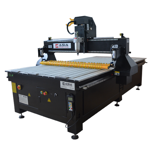
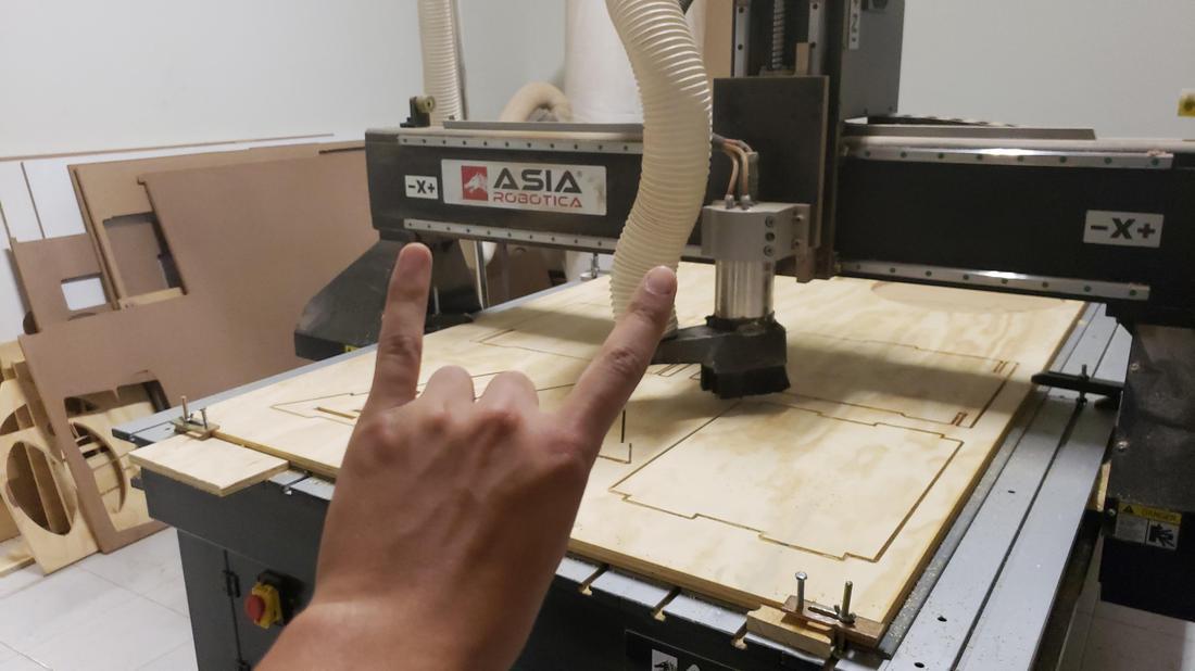
The machine that we have in the facilities of the fab, is the Asia Robotics SHOP1325, which I describe briefly below.
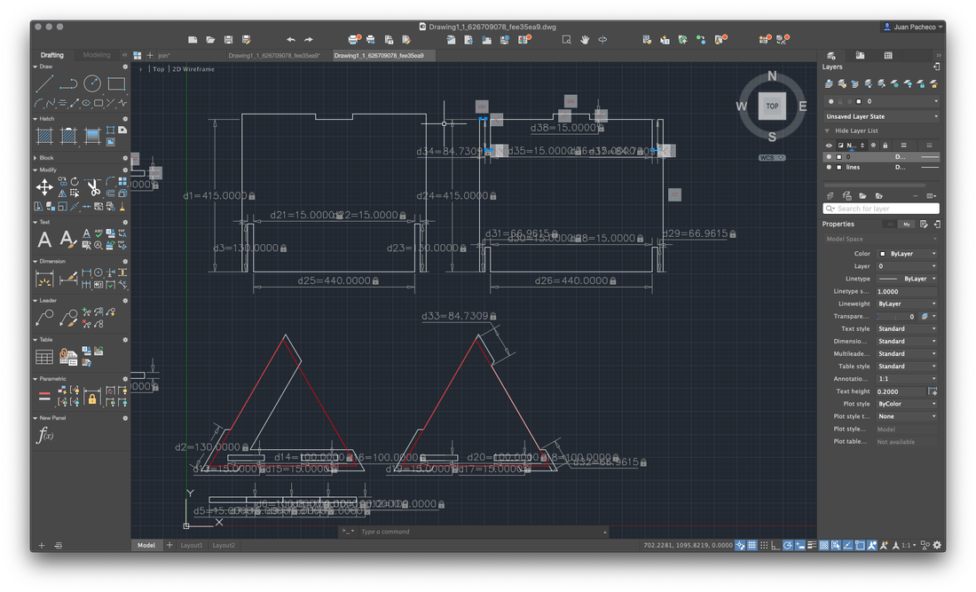
First we must build a 2D model in some CAD software, in this case I decided to use AutoCad, the assembly of the piece was at a distance of 15mm material. Then the file is exported in .DXF format
So that the machine can interpret the model, we use the Aspire software, which I had to install on my Macbook using Windows through Bootcamp, since there is no Mac version, a negative point in my opinion.
After installing it, it was necessary to install the PostProcessor corresponding to the machine we have, Asia Robotics. In this way, when we export it, only the one we will use to export will appear.
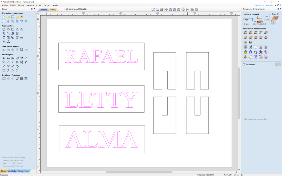
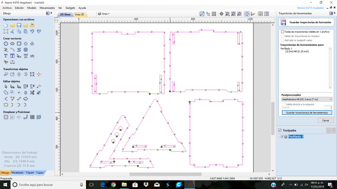
Once the Aspire software is open, we configure the values of our work area, in this case, the size of the wood sheet of 1220mm x 2440mm x 15mm, we move the position of origin XY and accept. Then we import our file and adjust if necessary. The software has basic tools where we can make certain adjustments.
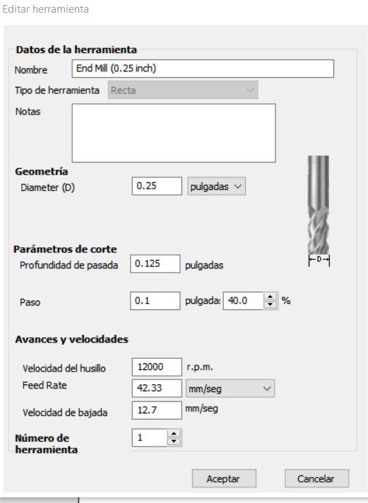
We select the vectors for engraving, which must be the first thing that the machine has to do, and then we configure the tool that we will use, in this case, the 1/4-inch bit. We generate the roads and simulate in 3D, the same software allows it.
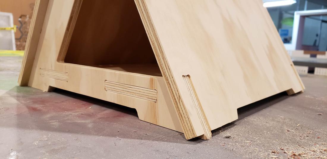
After doing the engraving, we precede to make the cuts or drawer, it is worth mentioning that to make assemblies it is recommendable to use backbones, in this way in the corners the tool will be a little more, generating a small circle inwards that will allow us to piece that fits reaches the bottom and makes a good connection.
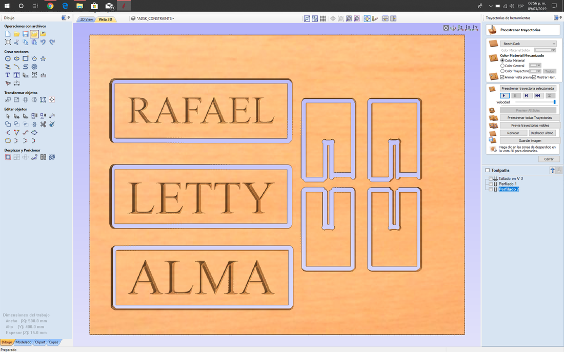
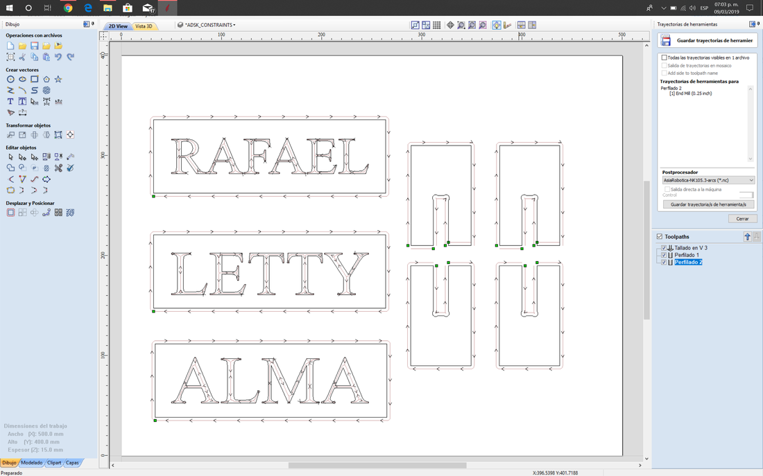
Finally, we export our files, selecting the appropriate Post Processor and save. In our case we first save the file for engraving and then the cut file and save it in an usb.
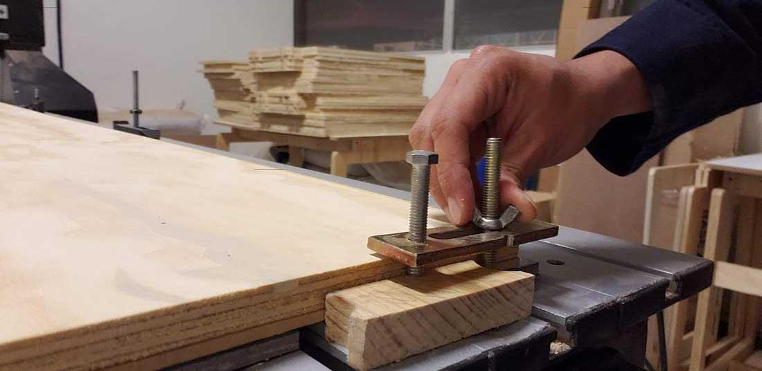
With the files in the usb, we proceed to connect it to the machine. Although before that, we must place our wooden plate on sacrificial bed placed in the machine. Then we adjust the plate to the base with the help of small presses, in this way we ensure that it does not move.
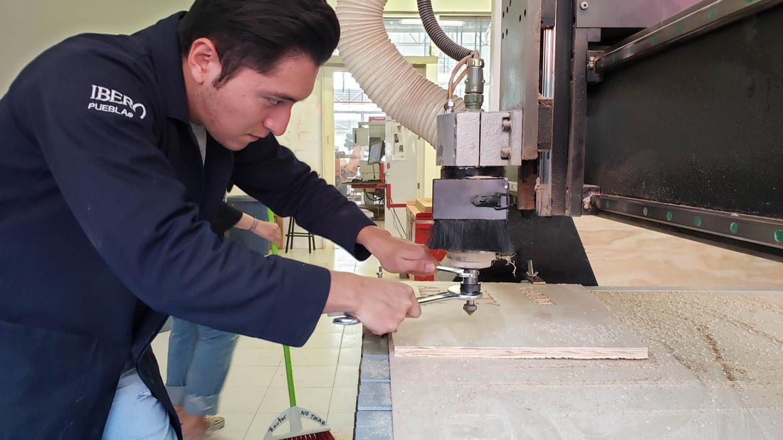
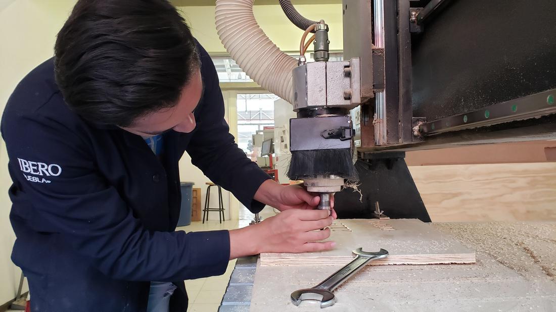
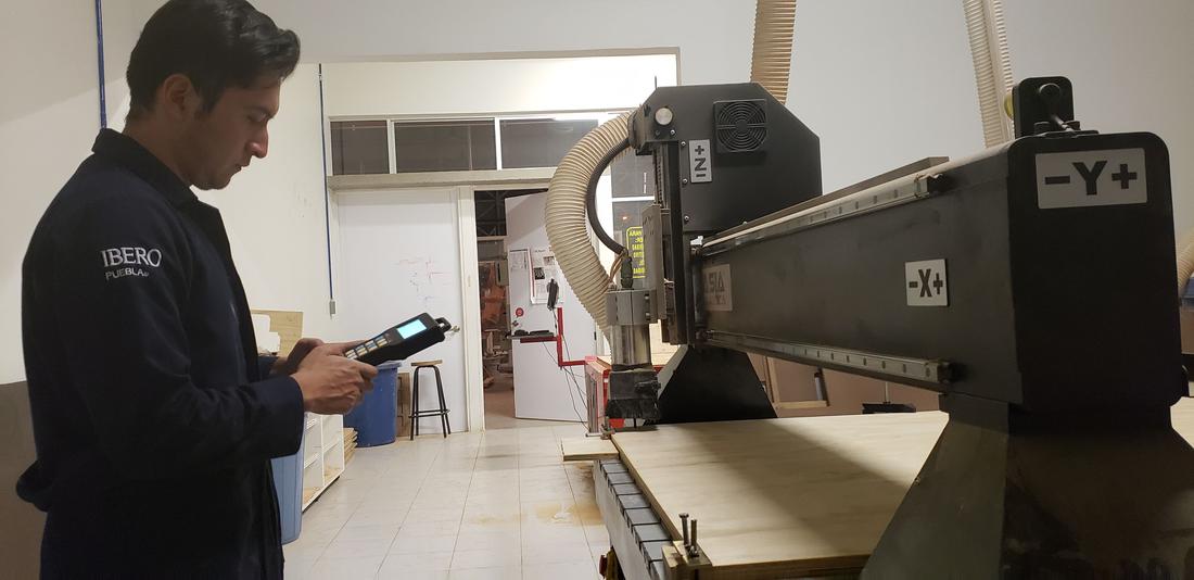
In the machine we adjust the values X, Y and later Z, to be able to locate it we approach the closest to the plate and then slightly adjust the tip of the tool to touch the wood. Then we upload the file we need and proceed to execute the process.
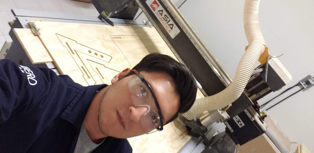
We must be cautious and have security measures, wear a gown, some protective glasses and boots.
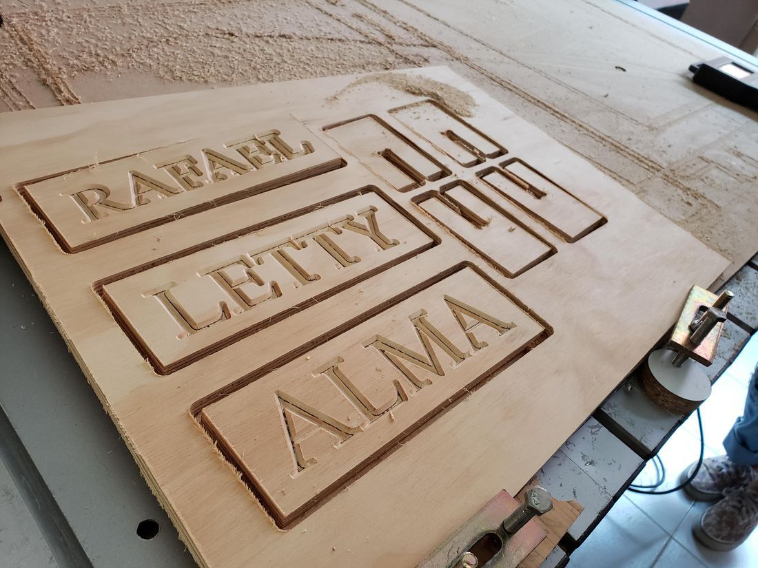
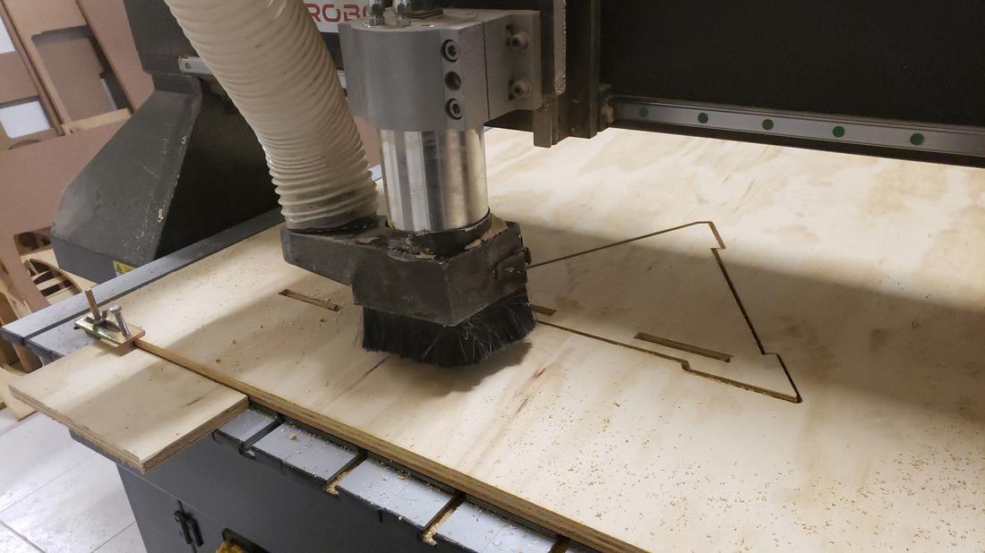
When I finished the engraving, we lifted the tool and proceeded to change the tip for the cutting. And we continue with the process. The result was the following.
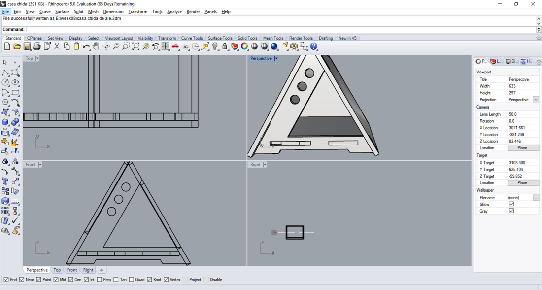
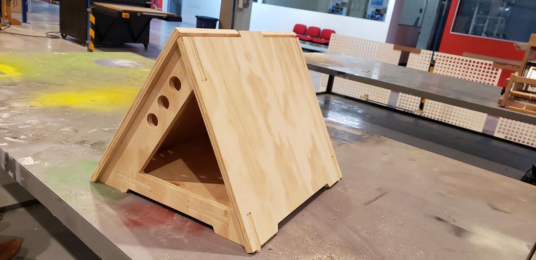
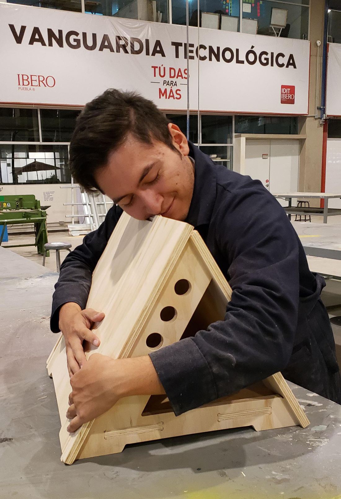
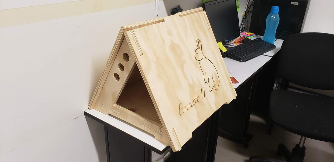
For this project, I decided to do something for my pet, a little rabbit, so I wanted to make a house, I was thinking about the design and decided not to follow the classic square houses, so I made my design based on an equilateral triangle.
Take as a reference the measure of the lying rabbit, so that it could lie down without space problems, so it is longer than wide. Then I show my sketch, and first I draw it in pencil before going directly to the CAD.
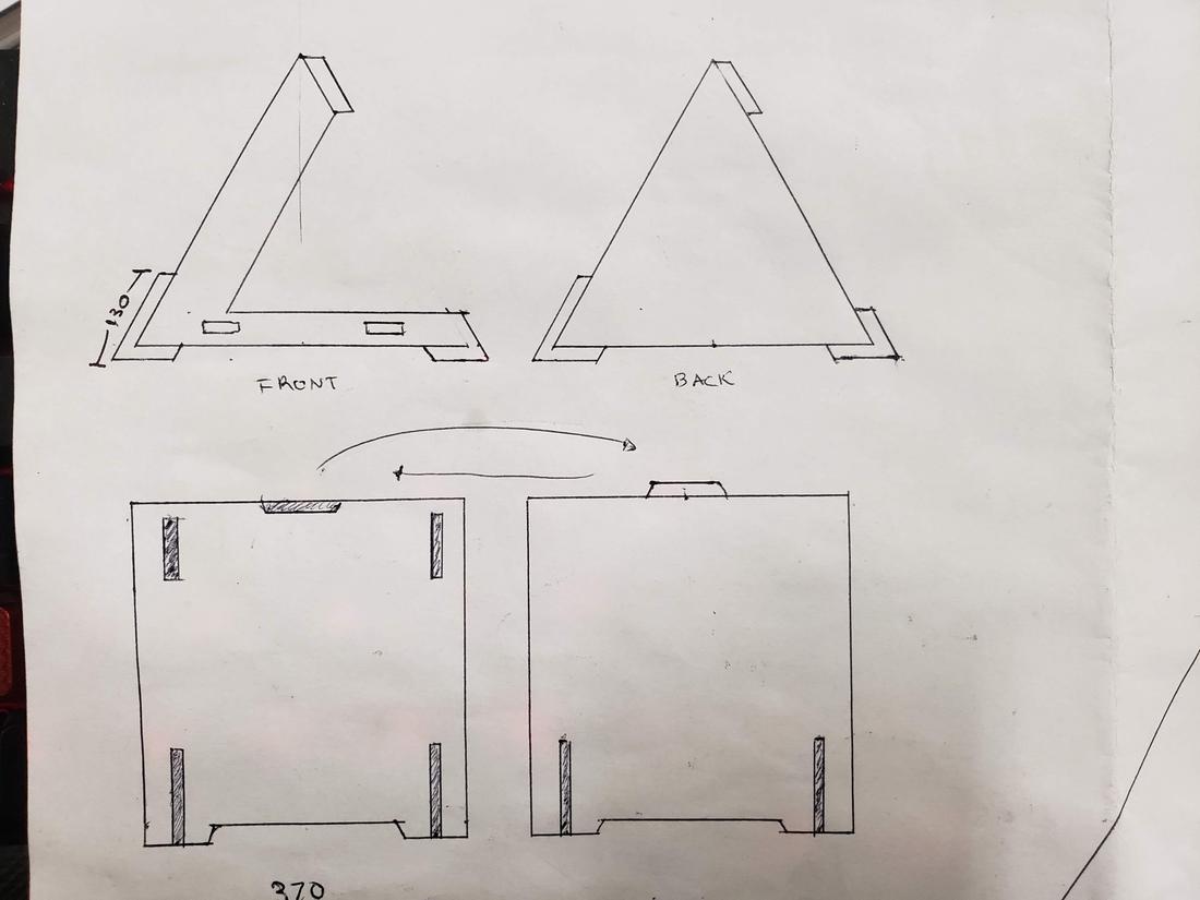
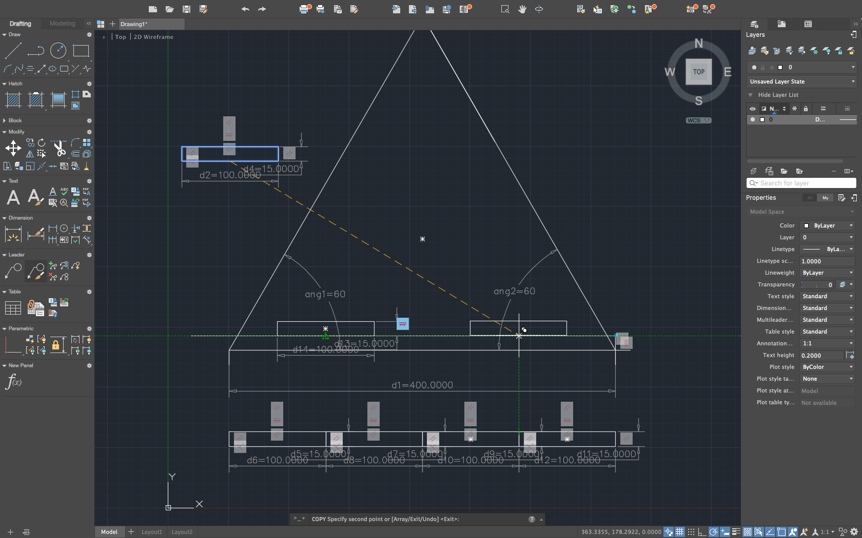
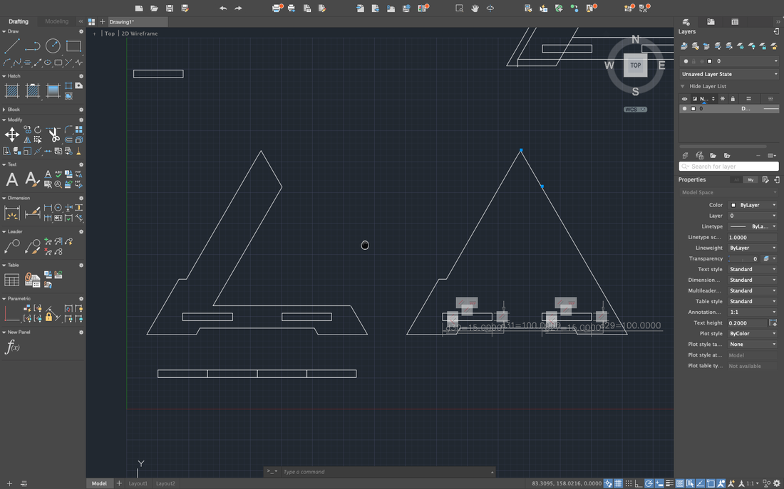
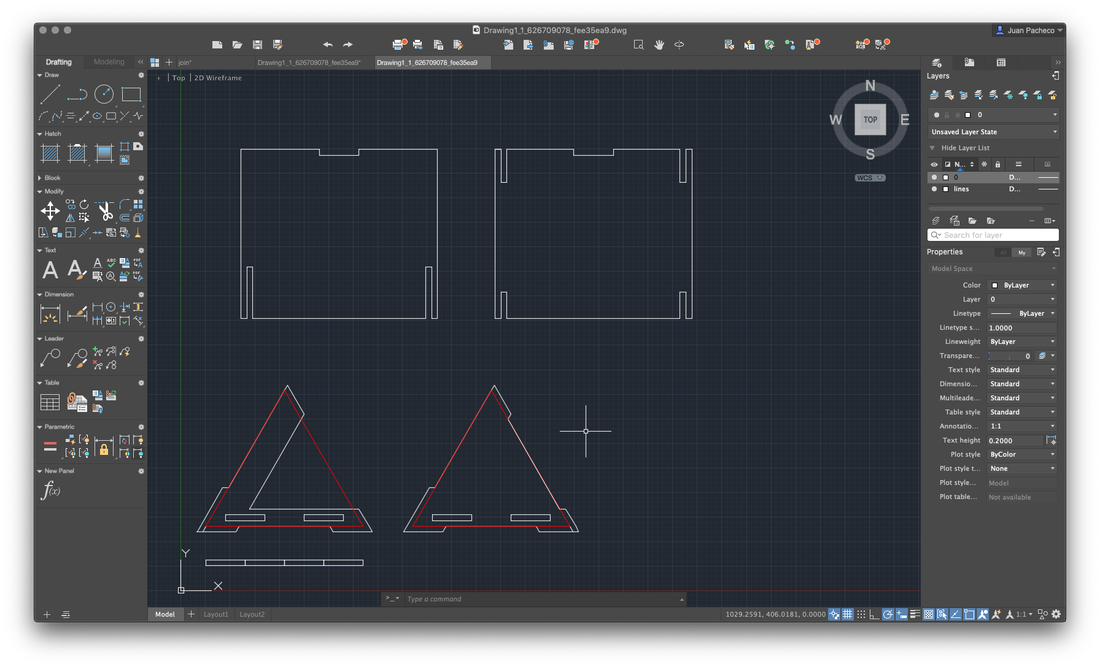
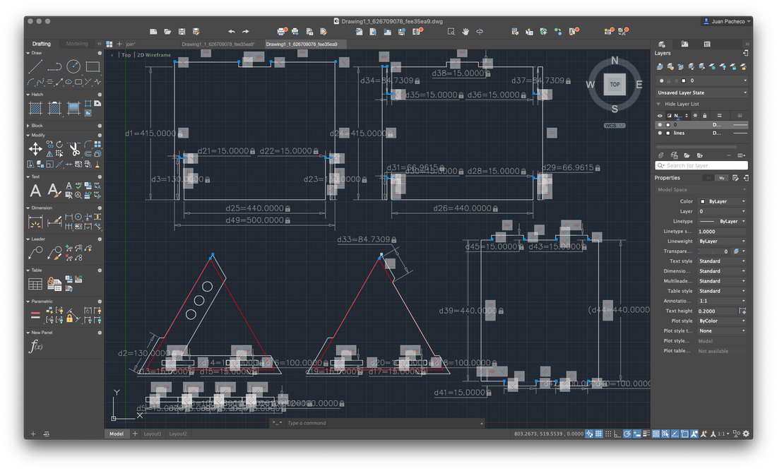
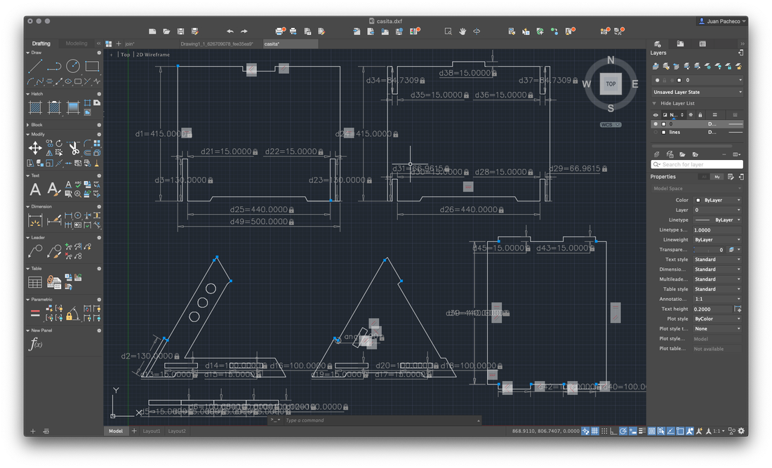
After landing the idea of my design, I proceeded to draw it in AutoCad, where I traced my lines, established constraints and made the parametric design. Here are some photos of the process.
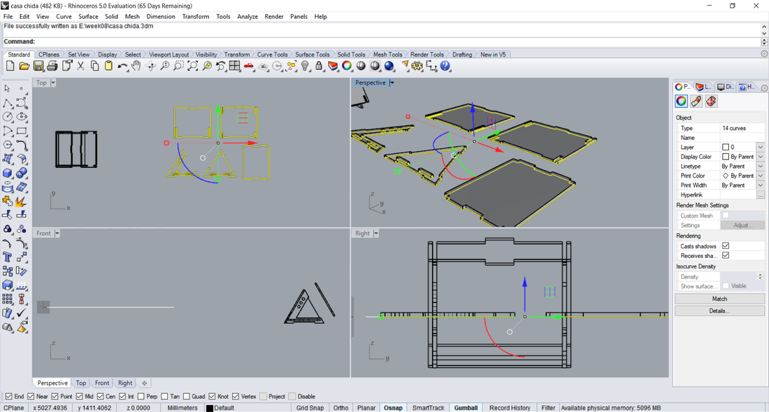
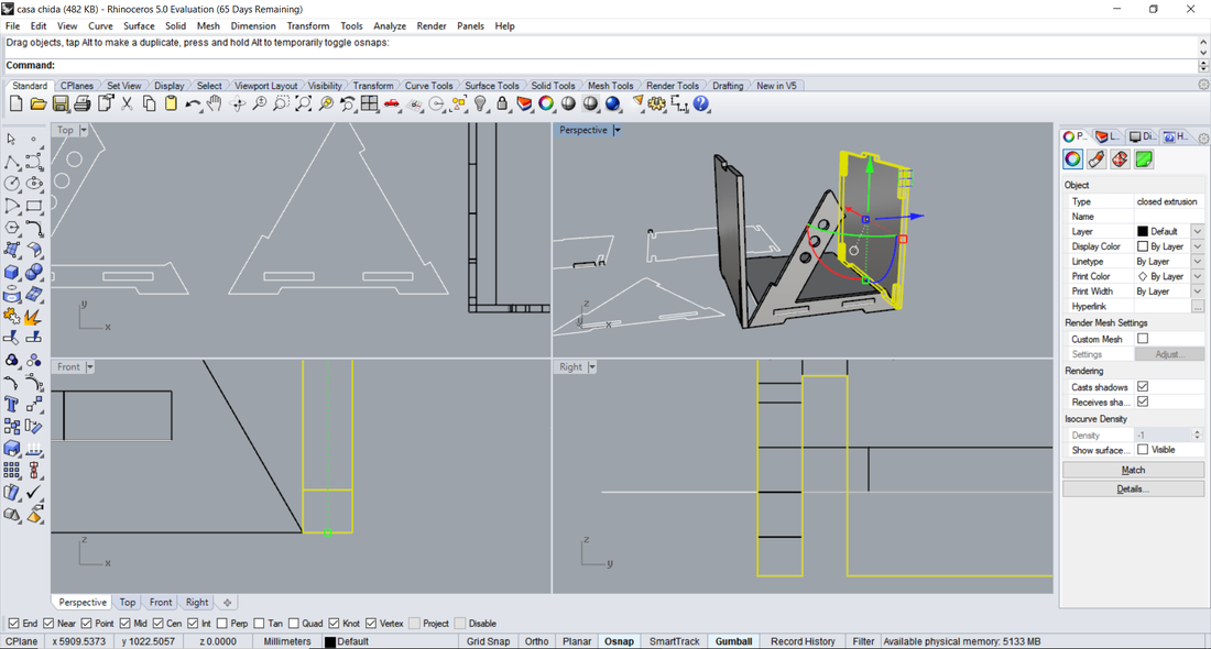
When I finished the drawing in AutoCad, before going to cut my pieces, I had a little uncertainty in case my pieces or assemblies did not fit very well, so I decided to do a simulation, turning my 2D drawing into a 3D design and assembling the pieces . For that I wanted to use a new software for me, so I used Rhino. Create a new file and import my 2D model, then select my pieces and extrude to 15mm. It was here that I found my first error, a piece did not extrude correctly because there were double lines and unconnected points, ie open vectors, so I had to return to AutoCad to modify that piece, export again in DXF and import into Rhino.
After correctly extrude the parts of my model, I turned and moved the pieces to achieve an assembly, here I found the second error, the walls did not assemble correctly, that is, having these walls at an angle of 60º, the cut of the assembly generated a spacing that was not aesthetically correct, in addition to that height stood out too much, so I had to make some adjustments from AutoCad.
Once I finished doing the simulation correctly, I proceeded to save my files in an usb and change operating system to use Aspire.
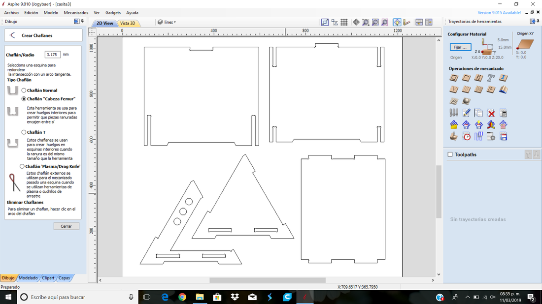
In Aspire, configure the parameters necessary for my design and try to generate the trajectories, however, the walls marked error, since there were still open vectors and, although the Aspire software has a tool for joining open vectors, it did not work. I had to go back to AutoCad and modify it. This procedure was a headache, since I tried it in several ways and did not generate the paths correctly. However, after so much frustration I managed to make my design correctly and Aspire was able to generate the paths correctly.
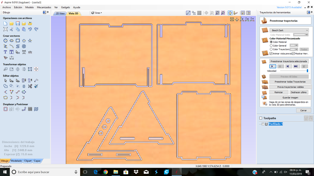
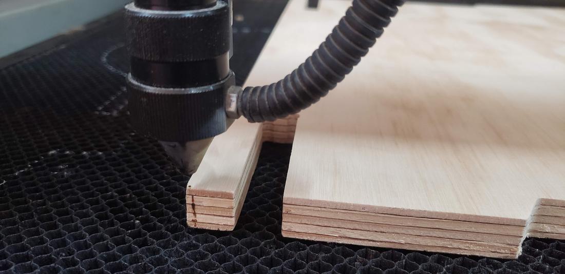
Export my file to be able to take it to the router, in this case it was only one of cutting. It should be mentioned that the cut in general was with the cut outside the line, but for the assemblies and circles of the triangles (front and back) were inside, thus ensuring that the spacing was the size of the material of 15mm. Save the file in an usb and proceed to download to the router machine to make my cut.
The bit he used for this project was the Amana Tool 46349 CNC Solid Carbide Spiral Plunge. Spiral bits combine a shearing action in cutting with an augering action in chip clearance. The shearing action yields an especially clean & accurate cut, while the augering action clears chips from the cut. The “down-cut” cuts from the surface down, leaving a smooth edge at the surface of the wood. The bit is specially designed for speed and finish when working with solid wood.
The table fastens it to the bed of the cnc router with some presses, in this way to prevent the table from moving.
To calculate the feed rate I apply this formula:
Where:
Below I show the process of this great feat.
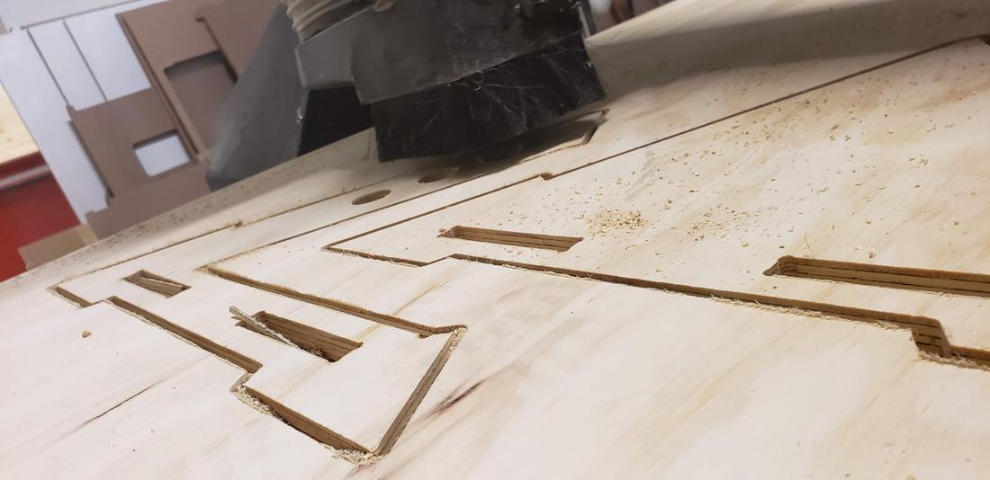
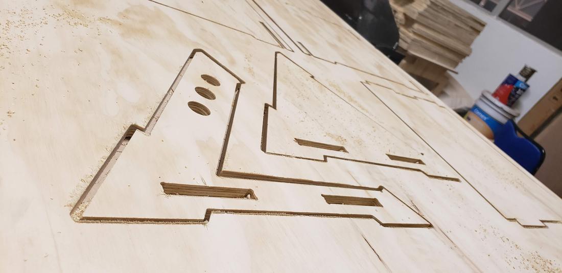
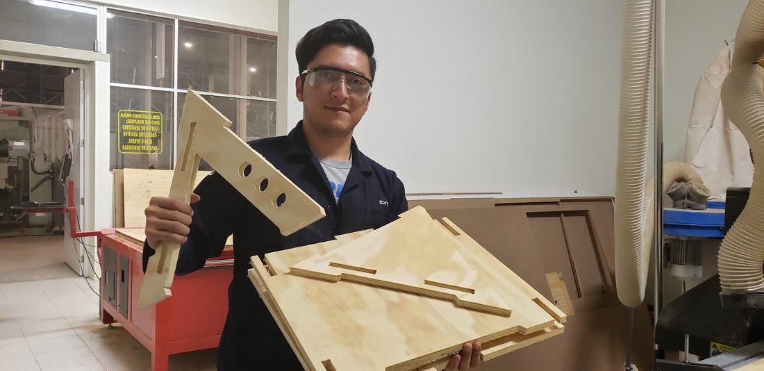
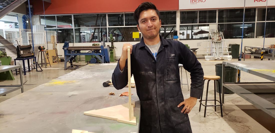
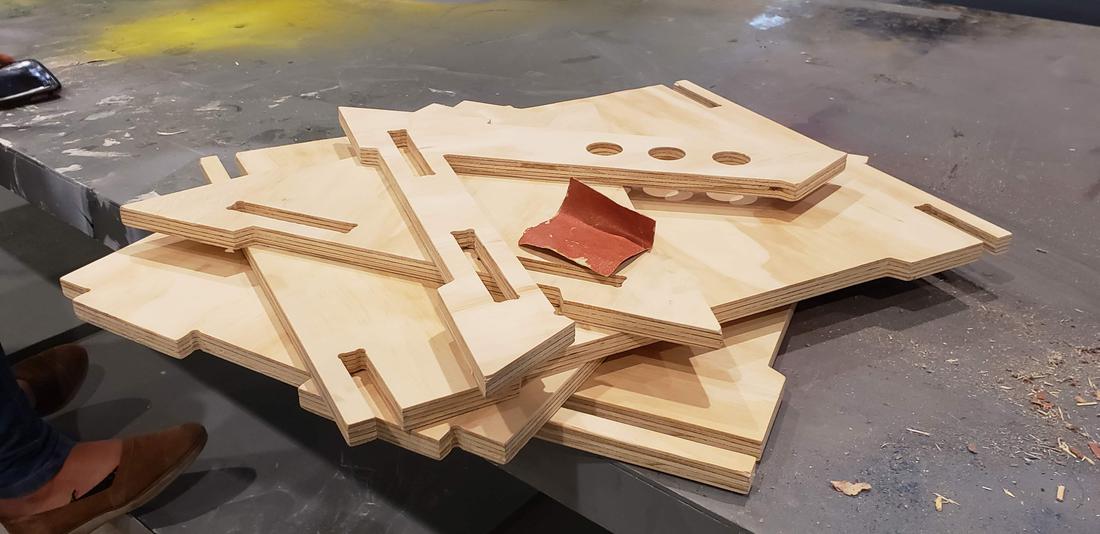
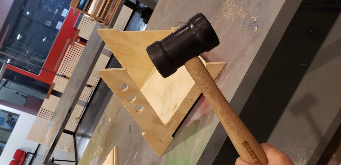
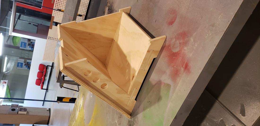
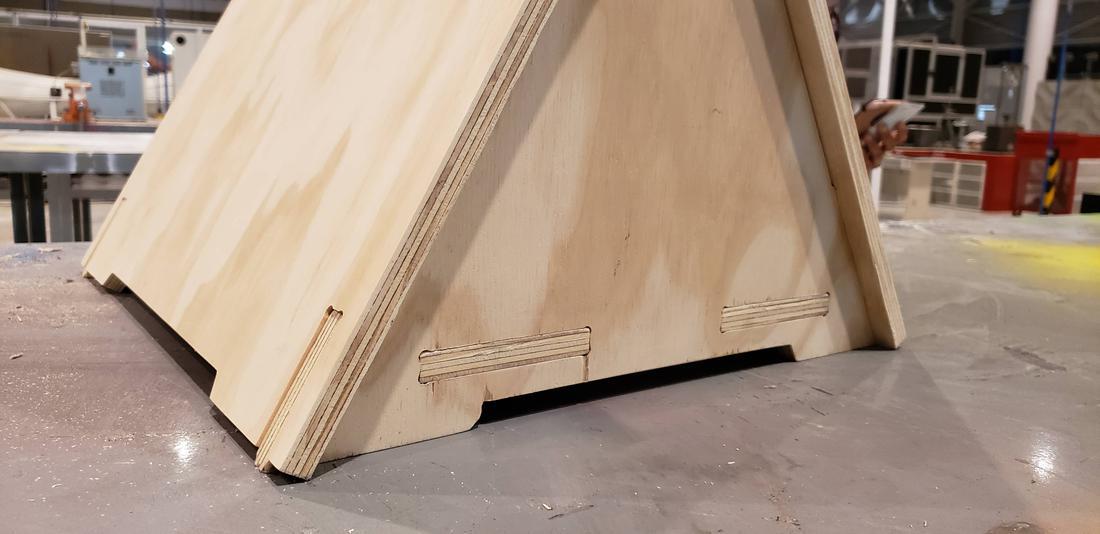
When the pieces came out, I proceeded to sand them to remove splinters and give a better finish and then began to assemble, after several hours of work, it was a great satisfaction when the pieces fit perfectly.
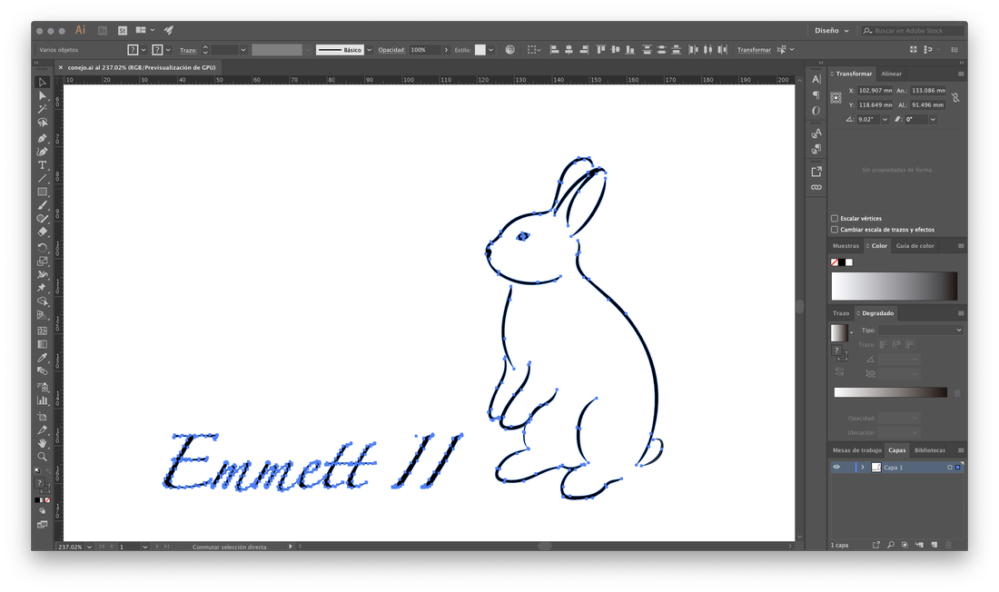
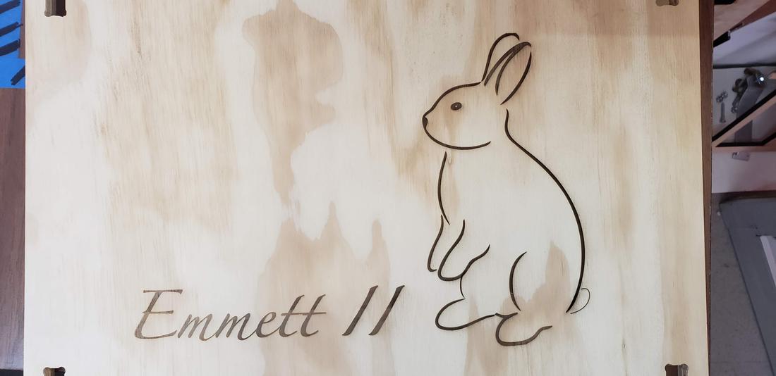
Finally, I wanted to make an engraving, so I designed in Illustrator a vector of my rabbit standing on 2 legs, with his name on one side, Emmett II.
This technique could have done it in the same router but because of the finish, consider that it would be more professional in the laser cutting machine, than better to apply the different techniques learned.

Below you can find the download links of the original files created for this week.