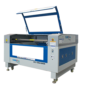
In the fab-lab Puebla facilities, we have two laser cutting machines, the one that is used is the CAMFive Laser Cutting Recorder CFL-CMA1080K, which has a work area of 1.00 x 0.80m, the table can go up and down automatically, besides having a rotating accessory with which it is possible to engrave cylindrical objects.
Below, I list the materials that can be cut and engraved with this machine:
After characterizing the laser cutter, they taught us how to use it, always respecting safety regulations. The first step is to verify that it is connected to the current, then proceed to turn on the power switch of the voltage regulator, which we have configured in 216V input voltage and 220V output voltage.
Then we turn on the machine, release the emergency stop button and insert the key. Turn the intensity knob and press the laser button, which will turn on white, indicating that the laser is active. From here we must be very careful, since the laser is not visible to the human eye.
To make a cut or engraving, there are two options, upload the file directly to the machine through the USB port, or through software that controls the machine. I must mention that the files must be in .DXF format
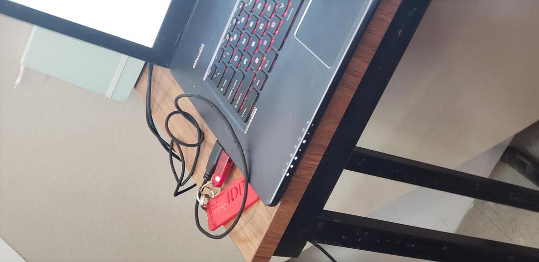
To use the software (SmartCarve), it is essential to connect a usb key, otherwise the software will not open.
Once the software is opened, we proceed to import our file, it will ask us to select the unit of measurement that we need, in our case in millimeters.
The software is very basic, but it has the necessary tools to adjust values or even create a design with primitives such as lines, circles and rectangles. It has a panel where the maximum and minimum intensity values of the laser are specified, as well as the speed, fundamental parameters for cutting or engraving.
It is possible to assign several layers with different configurations, this is useful, for example, to assign a layer for cutting and another for engraving. Note: The engraving must be first and then the cut, for this you can assign priorities from the control panel.
After assigning the drawing to the software and having configured the parameters, we can press the Start button, it will be loaded to the cutter and proceed to perform the magic.
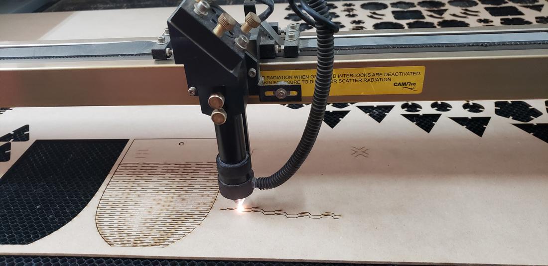
I must mention that we must configure the height of the laser tip between 5mm to 6mm with respect to our material, which we must place on the base of the cutter. The tests were made in 3mm MDF.
Test //
After characterizing the cutter, as a team we made some tests for cutting and engraving with different configurations and in this way, obtain the ideal configurations for the individual activities. We decided to create a document with our names with different configurations, varying between maximum and minimum power, as well as speed.
An important step is to calculate the kerf, which is a small part of material burned by the laser that we lose when making a cut. This kerf is presented on both sides where the laser passes, half and half. We must calculate this small measure to take it into consideration in our cuts, for example, in a press-fit is very important to fit perfectly our pieces.
Different materials and configurations of the cutter influence to a greater or lesser extent the kerf.
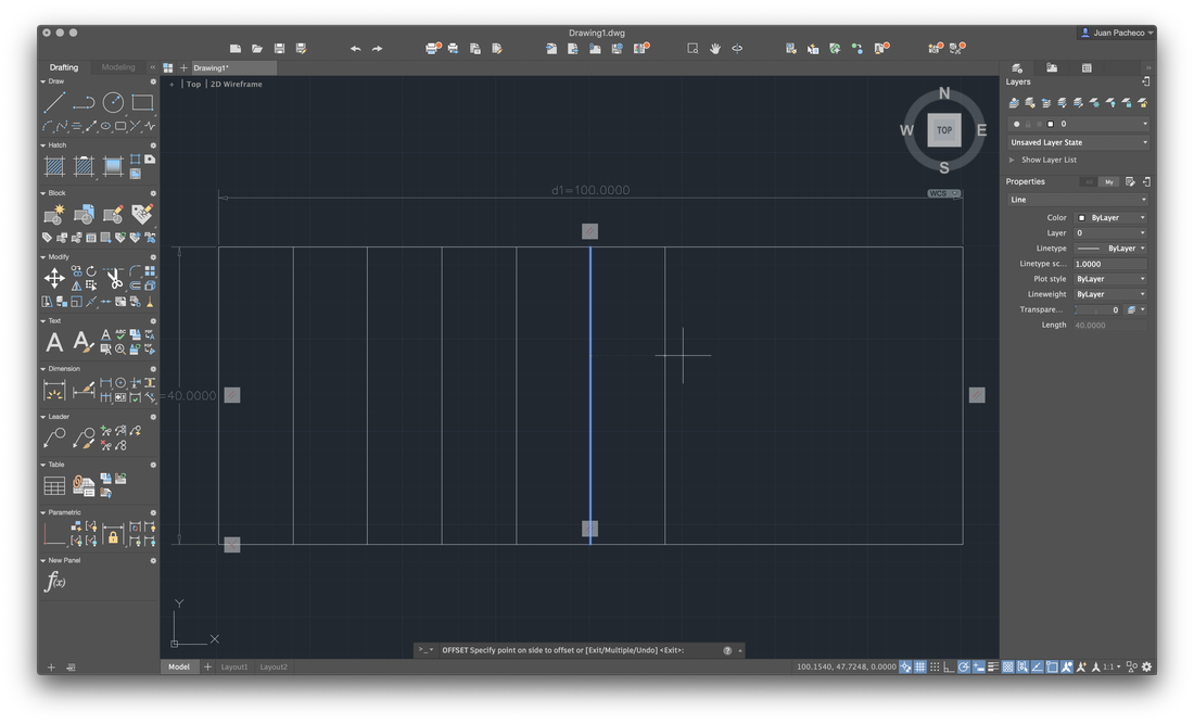
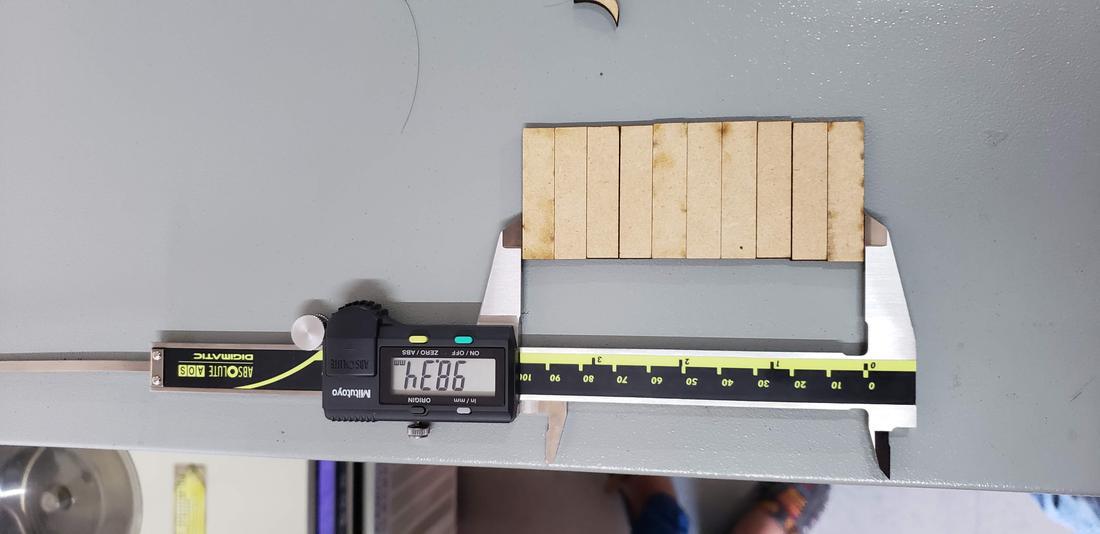
In order to calculate the kerf in the laser cutter, after having obtained the optimal cut values, we performed the following experiment. We draw a small grid of rectangles to proceed to cut them, then we join the rectangles and measure the space left over. The model was built in Autocad, a rectangle of 10mm * 40mm which contains 10 rectangles
Cut 10 rectangles result 11 cuts, LOL.
After cutting them, we put the pieces together and measure with a vernier. The formula we applied was the following: ((100-98.25) / 11) / 2 = 0.0795 value that we decided to round to 0.08 mm.
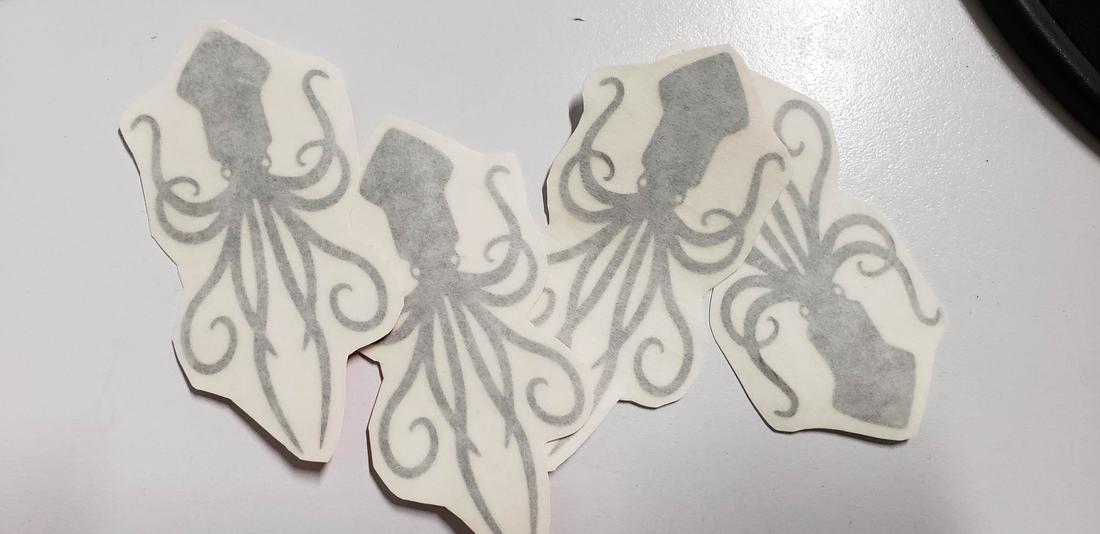
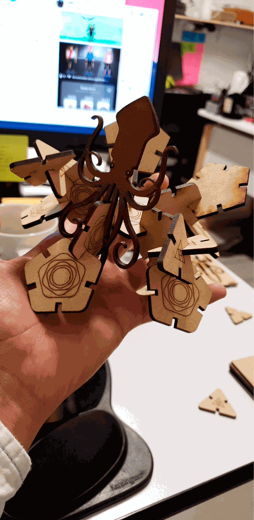
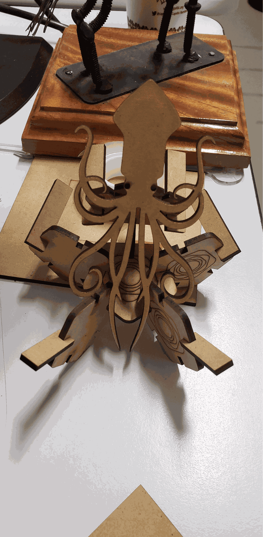
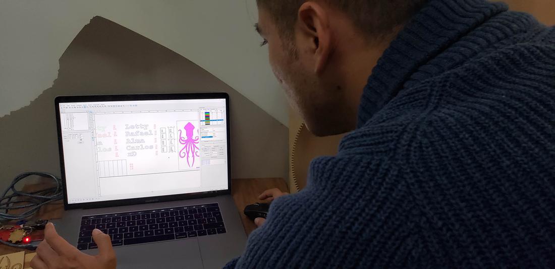
In addition to our names, configurations and table to calculate the kerf, I decided to incorporate a kraken that I previously vectored in Illustrator, as part of the team test.
In these four layers, which number is 11. 12 13 14, were set up in four fixed processing mode.Vetor graph in the layer, where there is a bitmap or a fill graph.or which is in scan mode, processing will not work. Please place them in different layer, and choose cutting mode for vetor layer.
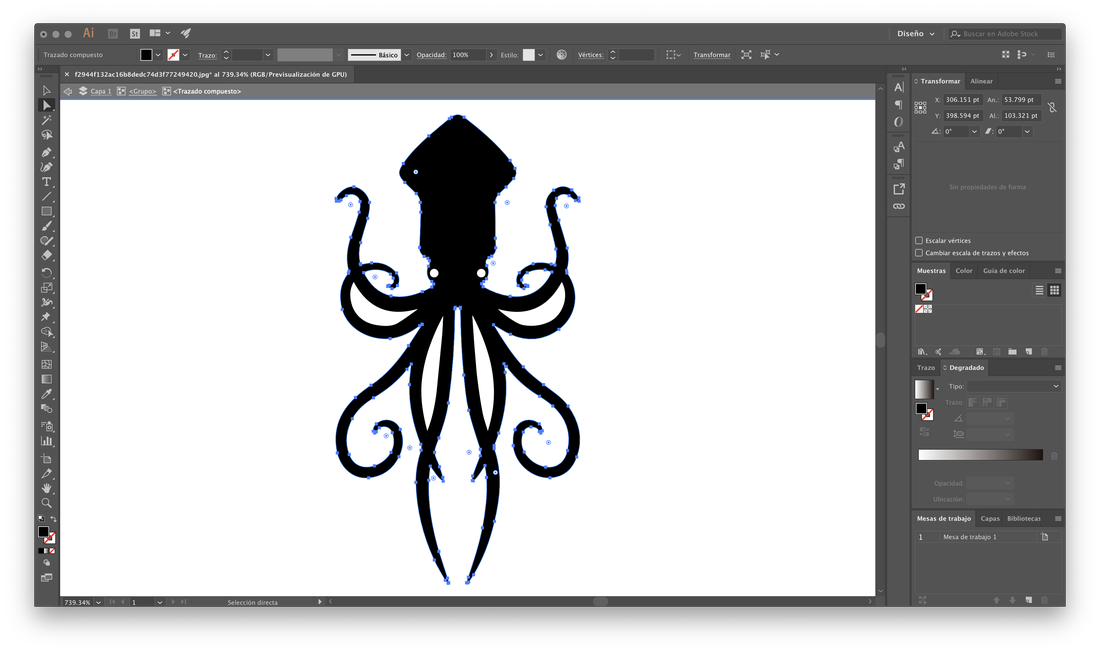
To be able to cut a drawing, it is necessary to vectorize the source image, for this we use Adobe Illustrator software and save it in .ai format in version 8, since it is up to that version it supports.
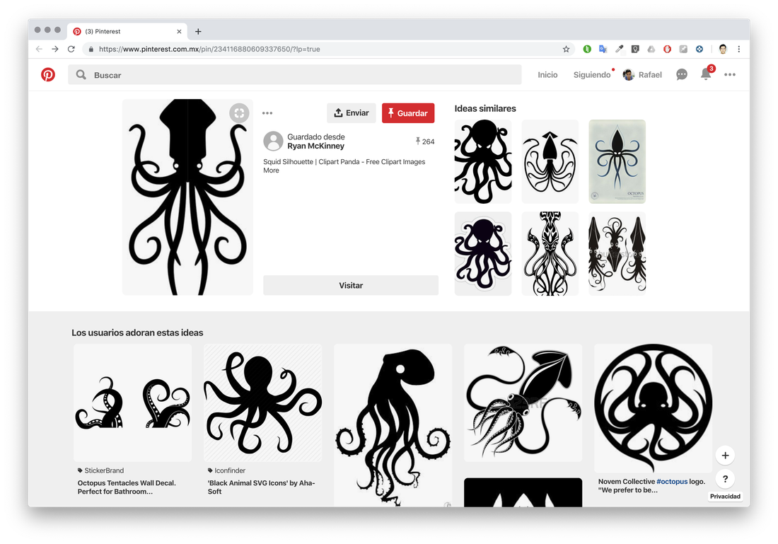
I decided to use the following image in jpg that I found in pinterest, to proceed to vectorize.
In Adobe Illustrator, load the image and proceed to vectorize using image tracing and. playing with the configurations I get the vector.
It is worth mentioning that there are other techniques to vectorize, for example, use the pen tool and follow the layout of the drawing, adjusting the Bezzier curves.
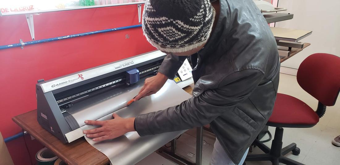
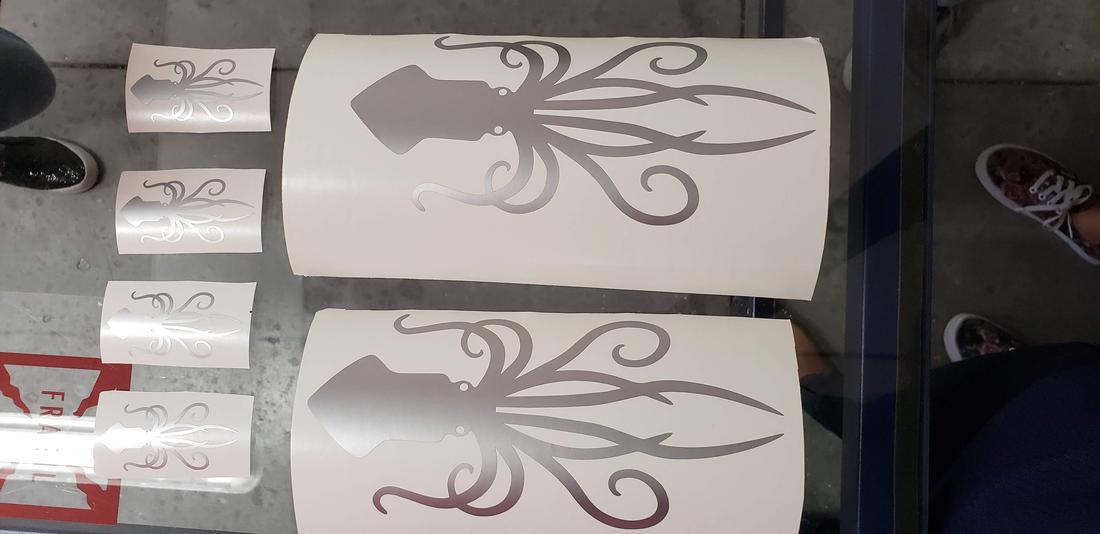
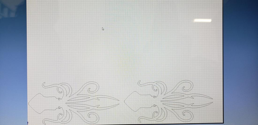
Then I saved my file and went to the vinyl cutter.
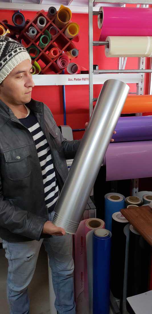
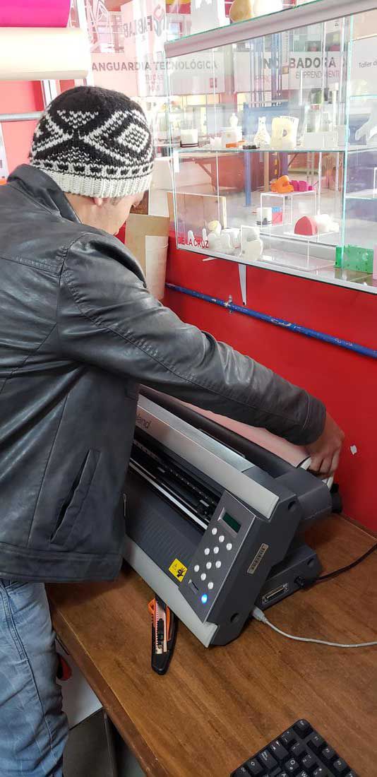
I chose the color of vinyl that I liked the most and put it on the machine, adjust the vinyl to the machine, secure the roll and adjust the clamping rollers. Then from the computer connected to the machine, import my file and proceed to send them to the cutter.
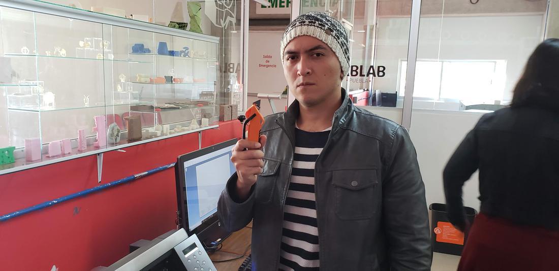
Below is a summary of the cutter blade design.
0.5 ±0.05 Offset: Distance from the center of the blade to the edge of the blade. The offset determines the
blade’s turning radius and how it compensates for distance while turning corners. Offset is specified by the
blade manufacturer.
55° Angle: The angle is specified in the measurement of degrees. The blade below is a 55-degree blade.
Ø1.0 Circumference: Lists the circumference of the blade tip.
Blade Settings
Below lists the optimal blade settings by application. These are general guidelines only and it is always recommended to send a cut test before sending any jobs.
Material
Cutting Force
Cutting Speed
Cardboard
250 - 400 gf
≦ 20cm/s
Flock
80 - 160 gf
≦ 20 cm/s
Floor Laminate
100 - 350 gf
≦ 30 cm/s
Heat Transfer
30 - 100 gf
≦ 30 cm/s
Magnetic
150 - 600 gf
≦ 10 cm/s
PerfCut
100 - 300 gf
≦ 30 cm/s
Reflective
100 - 350 gf
≦ 20 cm/s
Sandblast
100 - 500gf
≦ 20 cm/s
Twill
80 - 250 gf
≦ 30 cm/s
Vinyl ≤ 3 mil
30 - 100 gf
≦ 30 cm/s
Vinyl ≥ 3mil
100 - 300 gf
≦ 30 cm/s
Window Tint
80 - 120 gf
≦ 25 cm/s
I realized that to cut vinyl the machine is very fast, compared to the laser cutter.
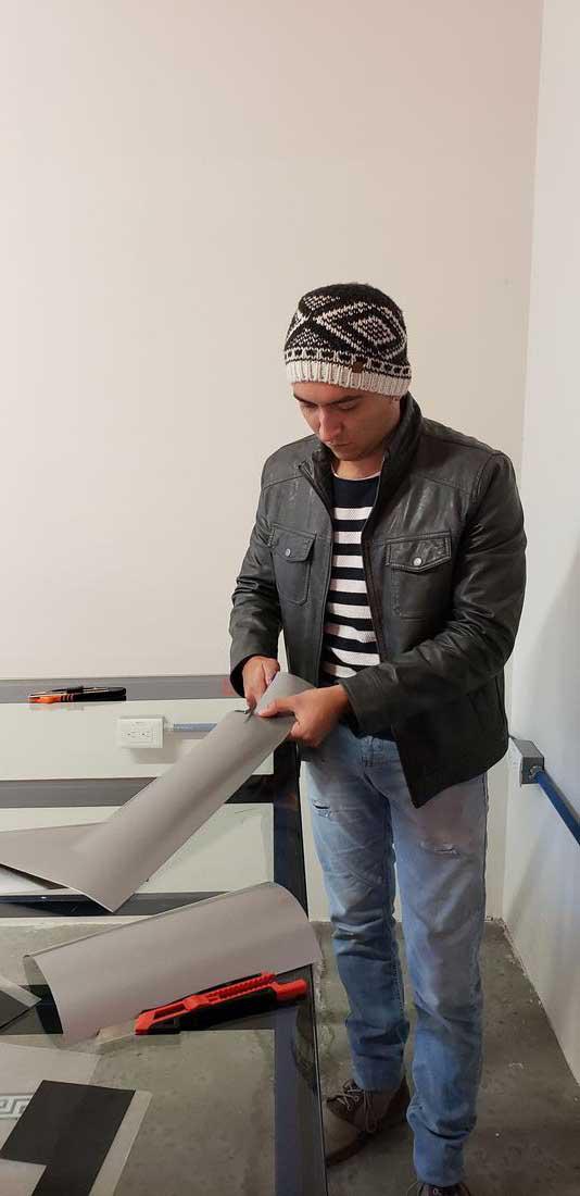
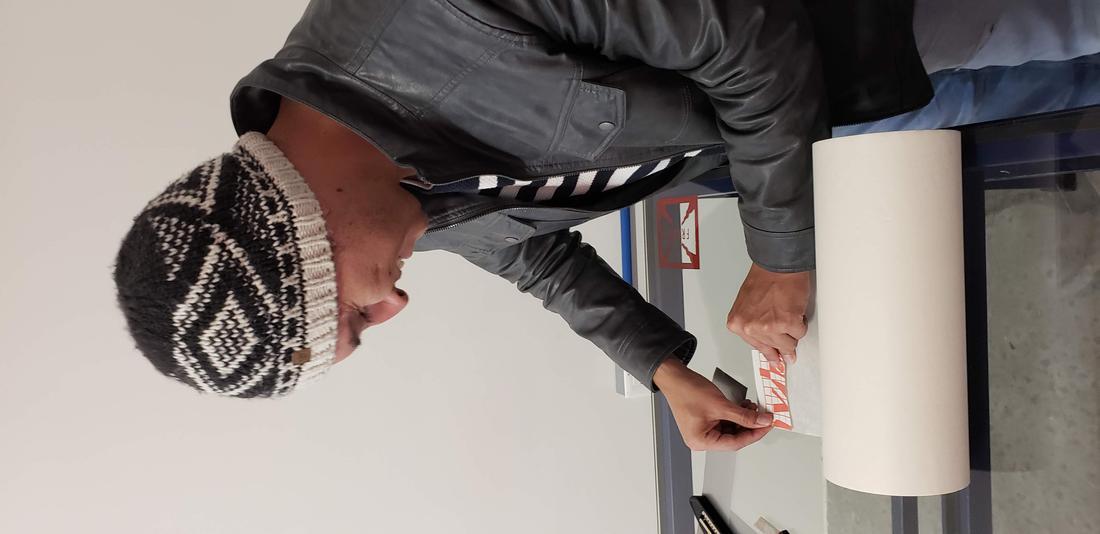
After finished, you should release some vinyl to proceed to cut with a cutter.
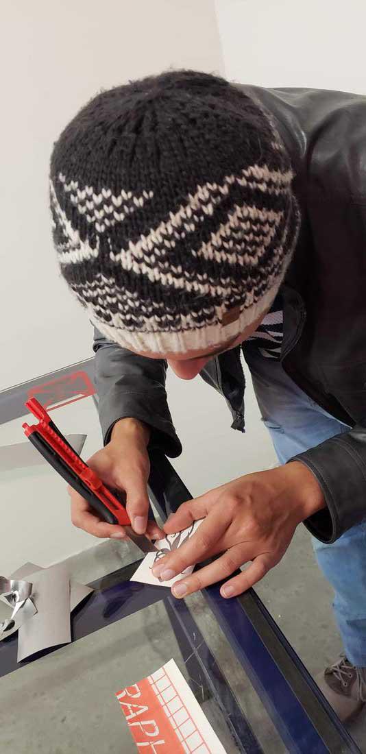
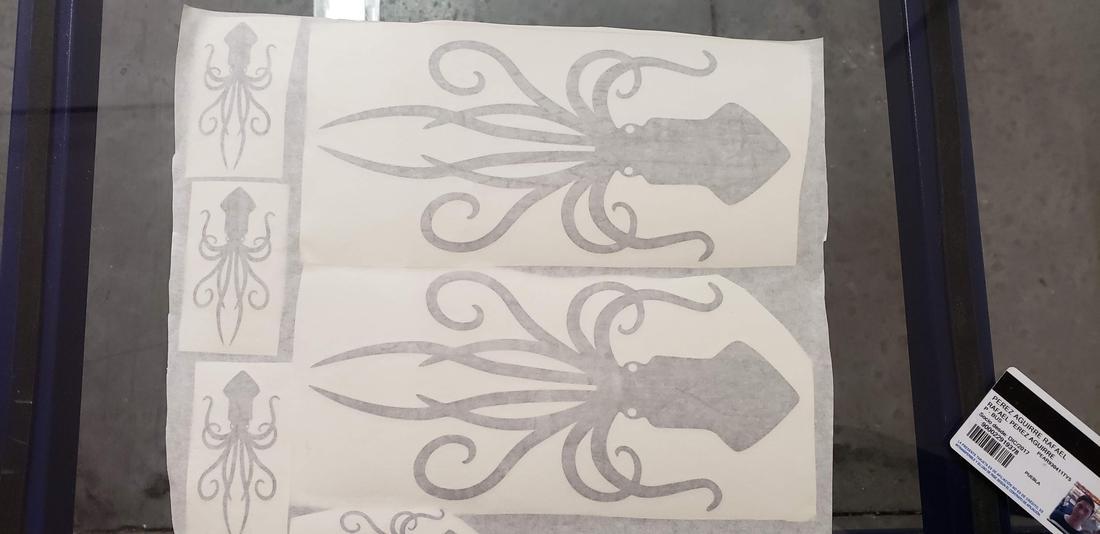
After that, it is necessary to trim the edge of the figure and separate the vinyl from our design and remove the surplus.
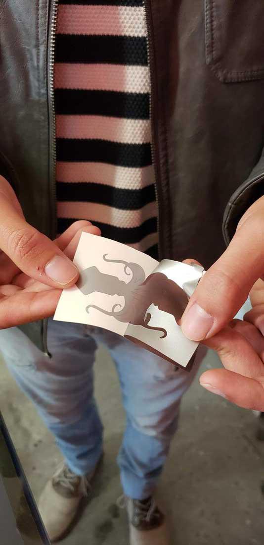
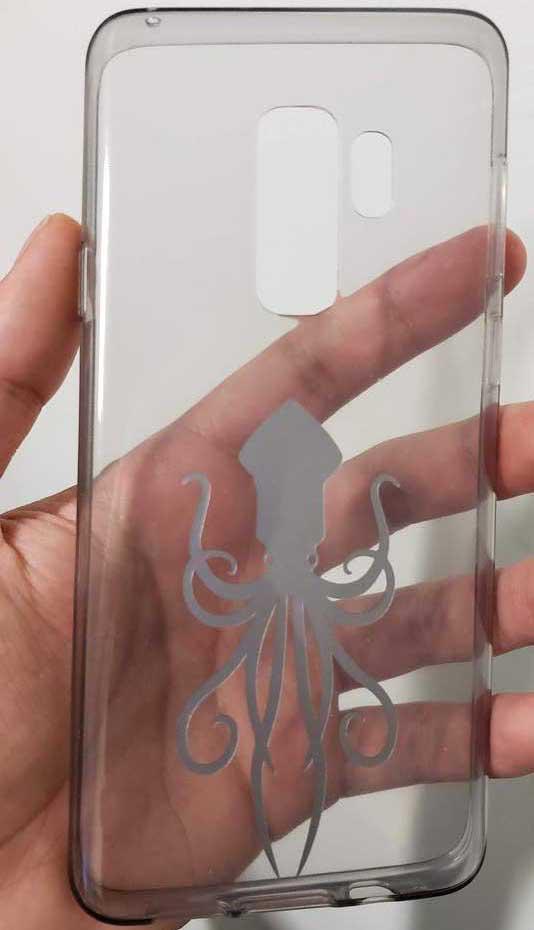
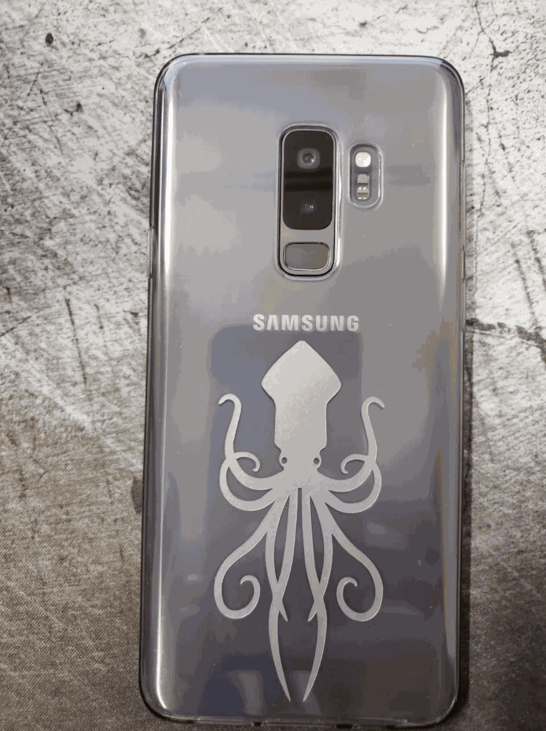
After cleaning the stickers, it is necessary to cover yourself with a film.
Finally, it is only necessary to cut them and detail the edges for a professional finish. Below is an example of the sticker stuck on the sleeve of my cell phone.
Press-fit construction kit //
For this activity, design a parametric press-fit construction kit. I decided to use AutoCAD for this task. Being honest I did not know how to design the pieces, that is, what form they would have or what they could form with them. At first I thought about creating a rhinoceros or a car, but these ideas were discarded since they would be unique pieces with only one purpose. So I thought of something more basic that would allow me to build several objects.
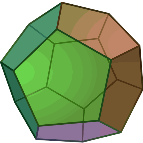
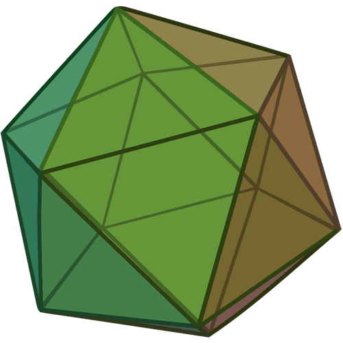
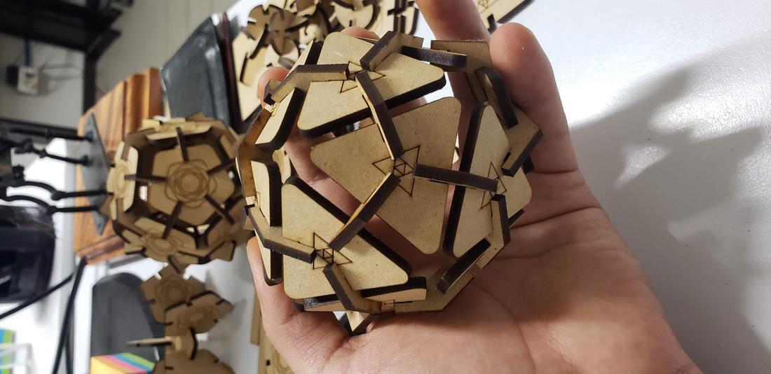
I was inspired by polyhedra, for example a dodecahedron and an icosahedron.
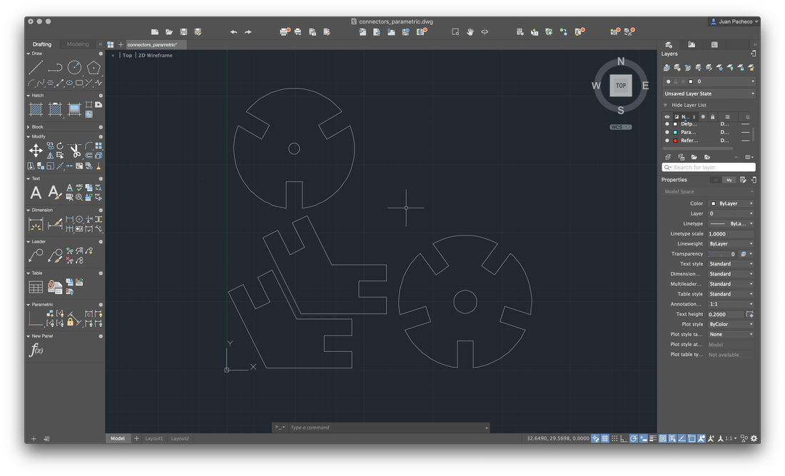
With these figures in mind, I proceeded to create the base in AutoCAD. My base figure was a circle of 25mm radius, with the draw a polygon of 5 sides circuscrito to the base, then create a small rectangle which placed at the base of my figure and use the tool ArrayPolar, where you specify the point of origin and the number of times of repetition. Then select the array and explode the element so that the pieces remain independent.
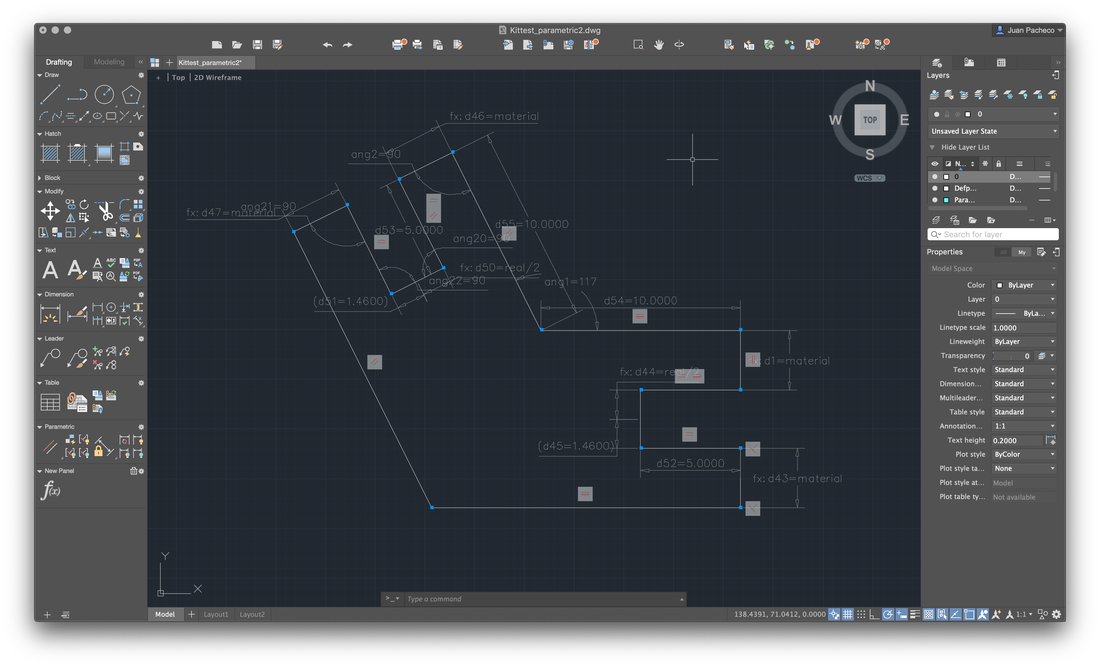
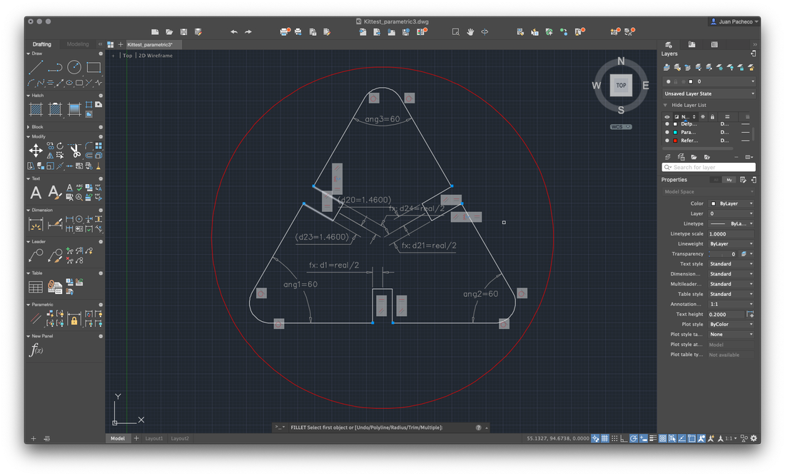
For the design to be parametric, you must add constraints, many constraints! Use the Parameters Manager where you defined the following:
Parameter: material Expression: Value: 3.0000
Parameter: kerf Expression: 0.08 Value: 0.0800
Parameter: real Expression: material-kerf Value: 2.9200
Parameter: max Expression: Value: 25.0000
With these measures as a basis, I put them to the different strokes of my drawing.
In this way, if the material were to change, for example the thickness to 6mm, just change the material variable to 6mm, in automatic rescale my drawing. The same thing happens if I had to modify the value of the kerf.
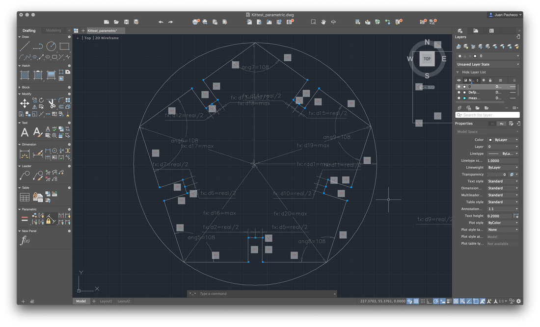
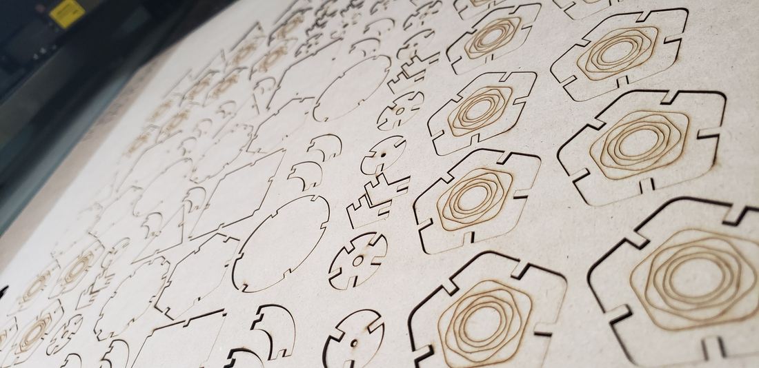
In addition to these pieces, I decided to create connectors that would allow me to form a dodecahedron, among other figures. To do this, draw the following figure, giving an angle of 117º.
Not in accordance with the design of my piece, I decided to apply a fillet to the edges and add a small drawing to engrave the pieces.
Add other small pieces as extra connectors, in order to increase the ability to create figures and pieces in the form of a triangle.
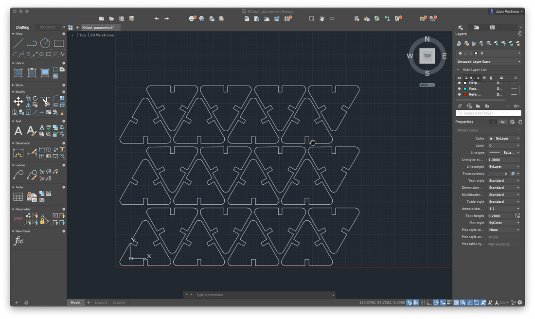
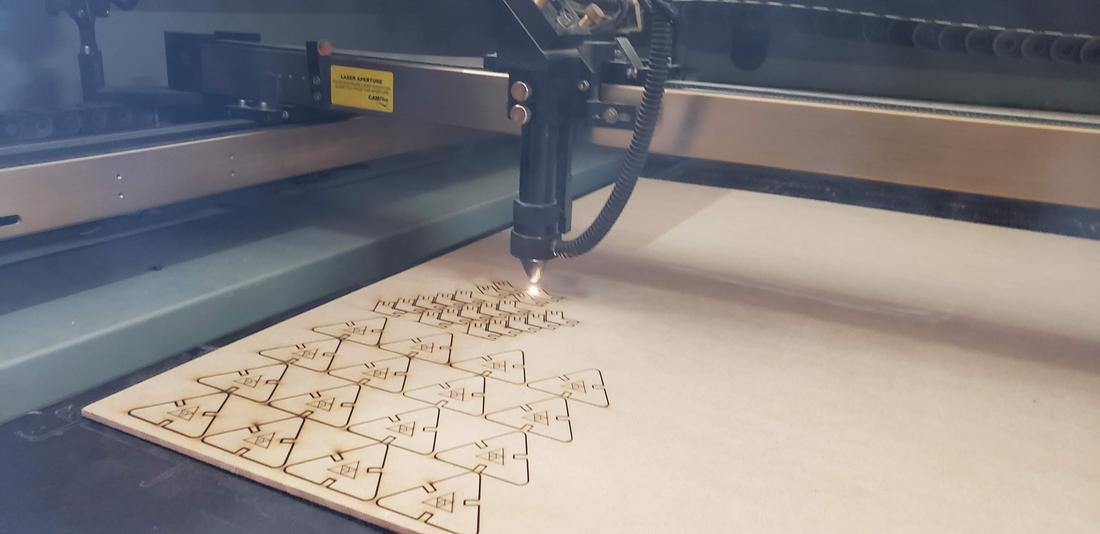
At the end, replicate and adjust the pieces to form a construction kit and save the file in .DXF format
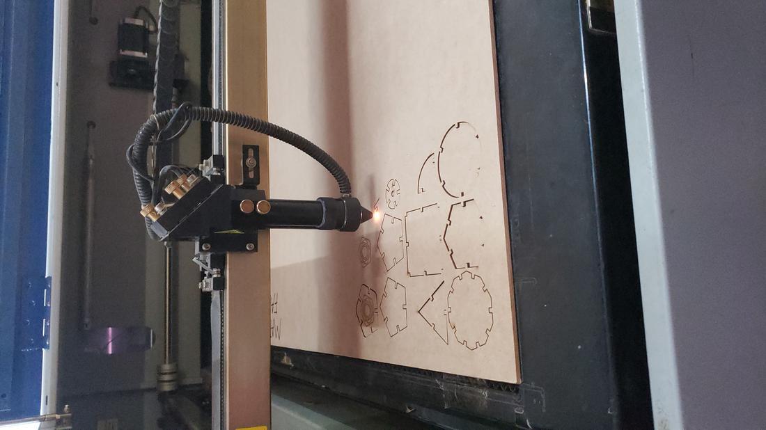
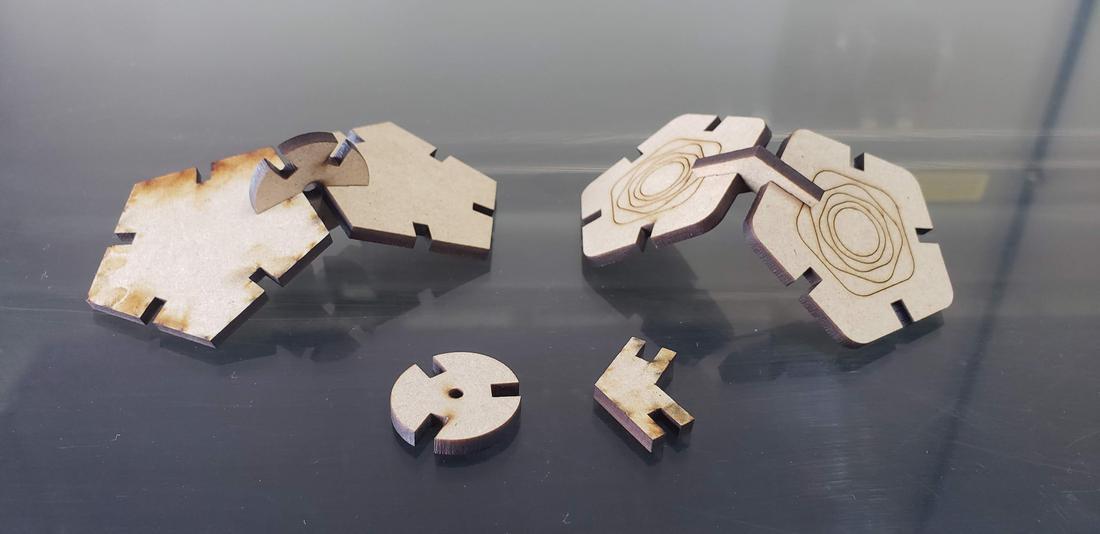
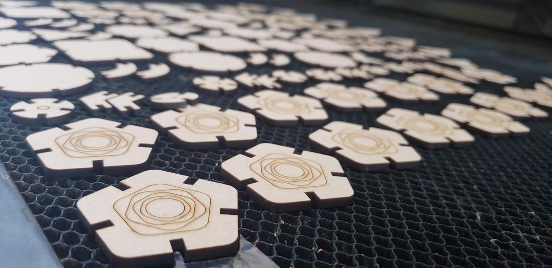
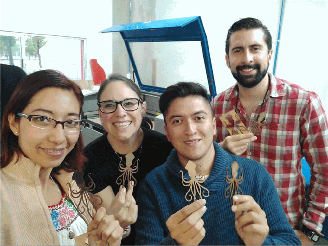
The first batch of pieces I cut with my partner Lety, cutting only a few to verify that they could assemble correctly. The result was successful, so I duplicated several pieces for my kit.
The parameters used for cutting were Max Power 60, Min Power 50 and Work Speed 18. For engraving were Max Power 25, Min Power 20 and Work Speed 40.
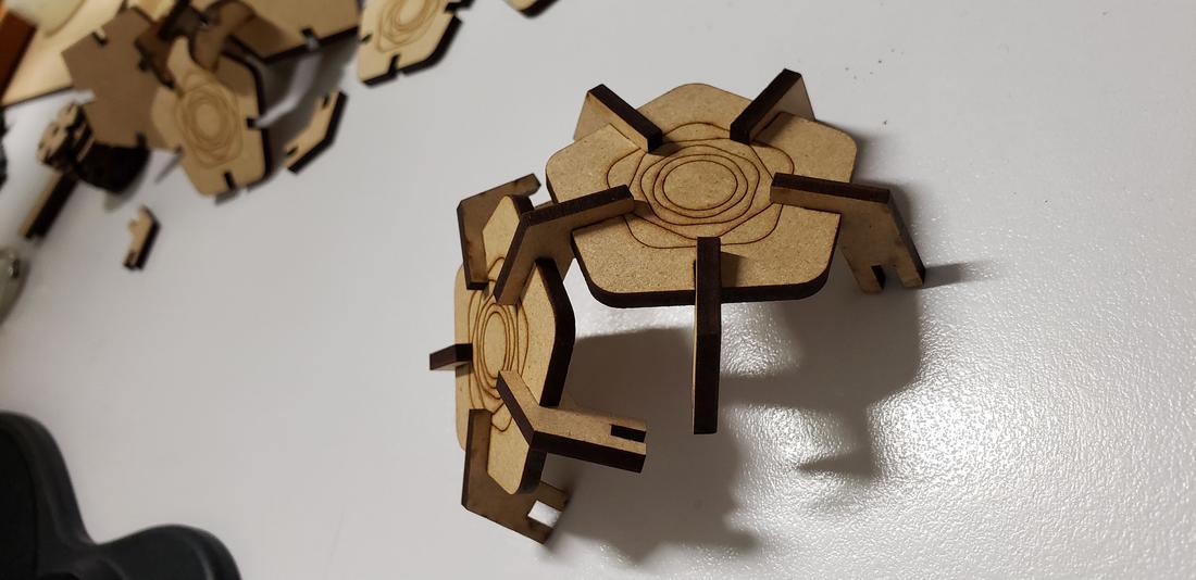
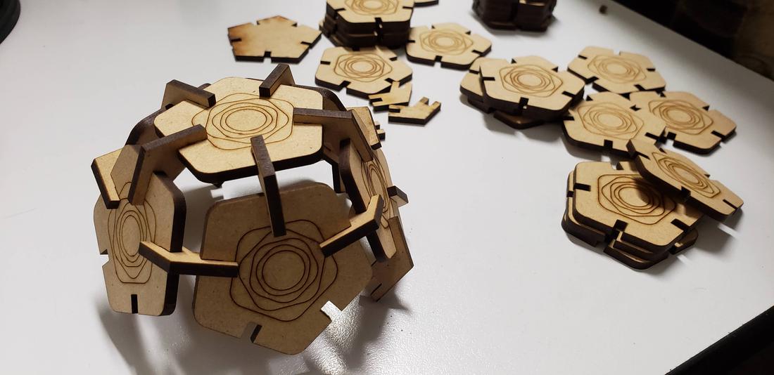
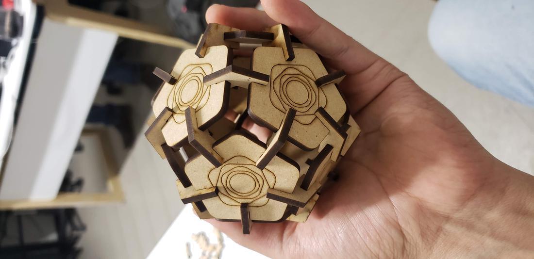
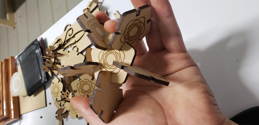
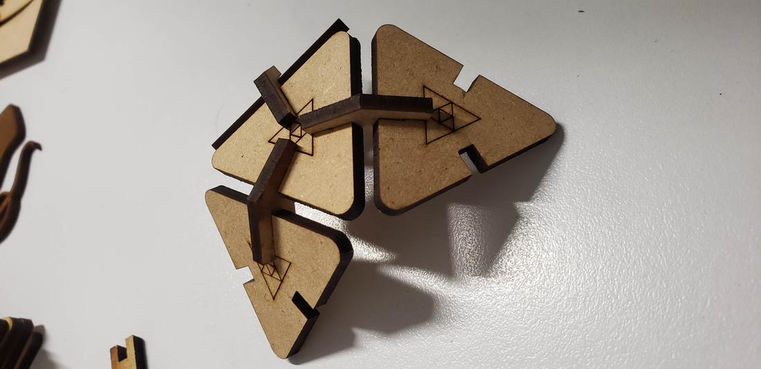
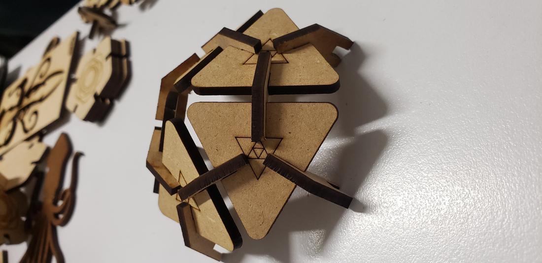
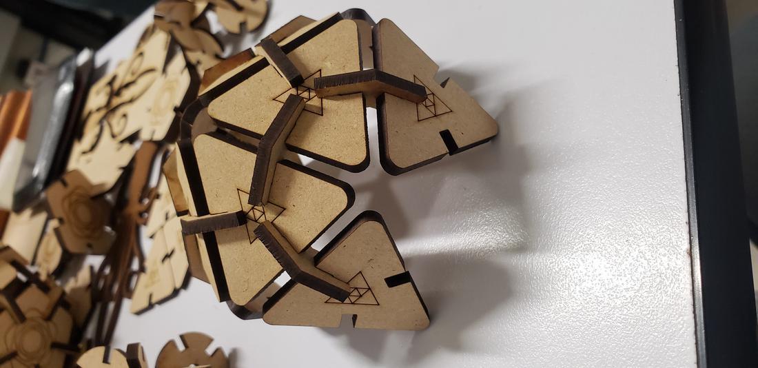
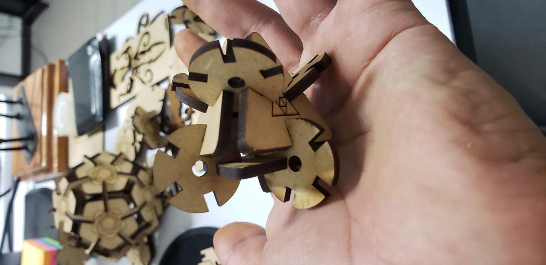
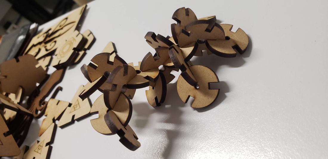
Next I show some formed figures:
Finally, I cut the second set of pieces for my kit, in addition to adding a living hinges design in order to play with the flexibility that can be given to a solid object. It is worth mentioning that this part of living hinge is not designed by me, it was a design I found on the internet, but it allowed me to know this technique and check several flexible designs.
Finally, I show some more figures that are possible to put together with my press-fit kit, in the end your imagination is the limit of figures that you can create!
The files //
Below you can find the download links of the original files created for this week.


 16.11.22.png)