Week 8. Computer Controlled Machining
Go to:
1. Group work
Task: Test runout, alignment, speeds, feeds, and toolpaths for your machine.
This week the group was all Oulu Fab Academy students together. The pictures are taken by Jobin.
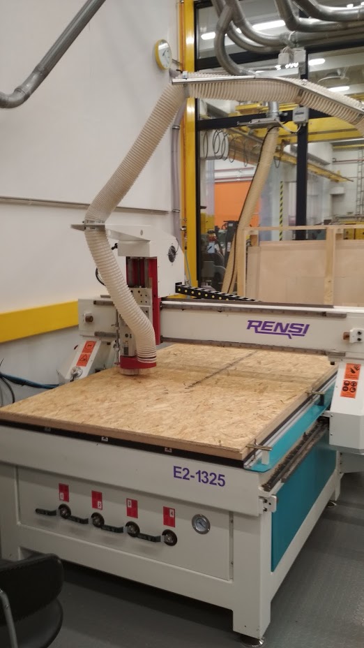
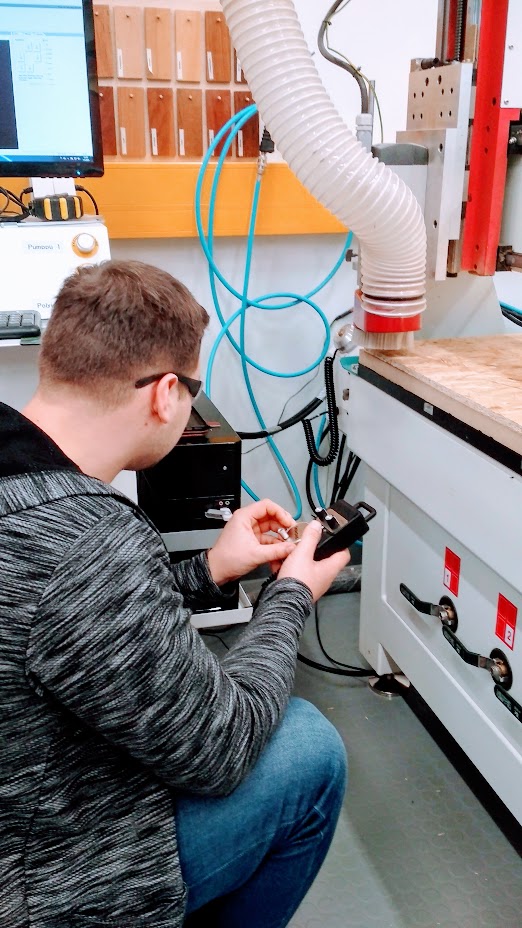
Eino showed us the CAM operations needed to prepare nc-file for cutting. He also showed how the machine works and gave the safety instructions. You always need to have safety glasses on when using machine. Also hearing protection is needed.
We went through following issues:
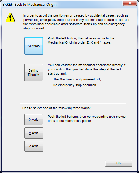
- Starting (powering on)
- Software
- Resetting axels
- Moving spindle (X, Y, Z), Computer & Hand wheel
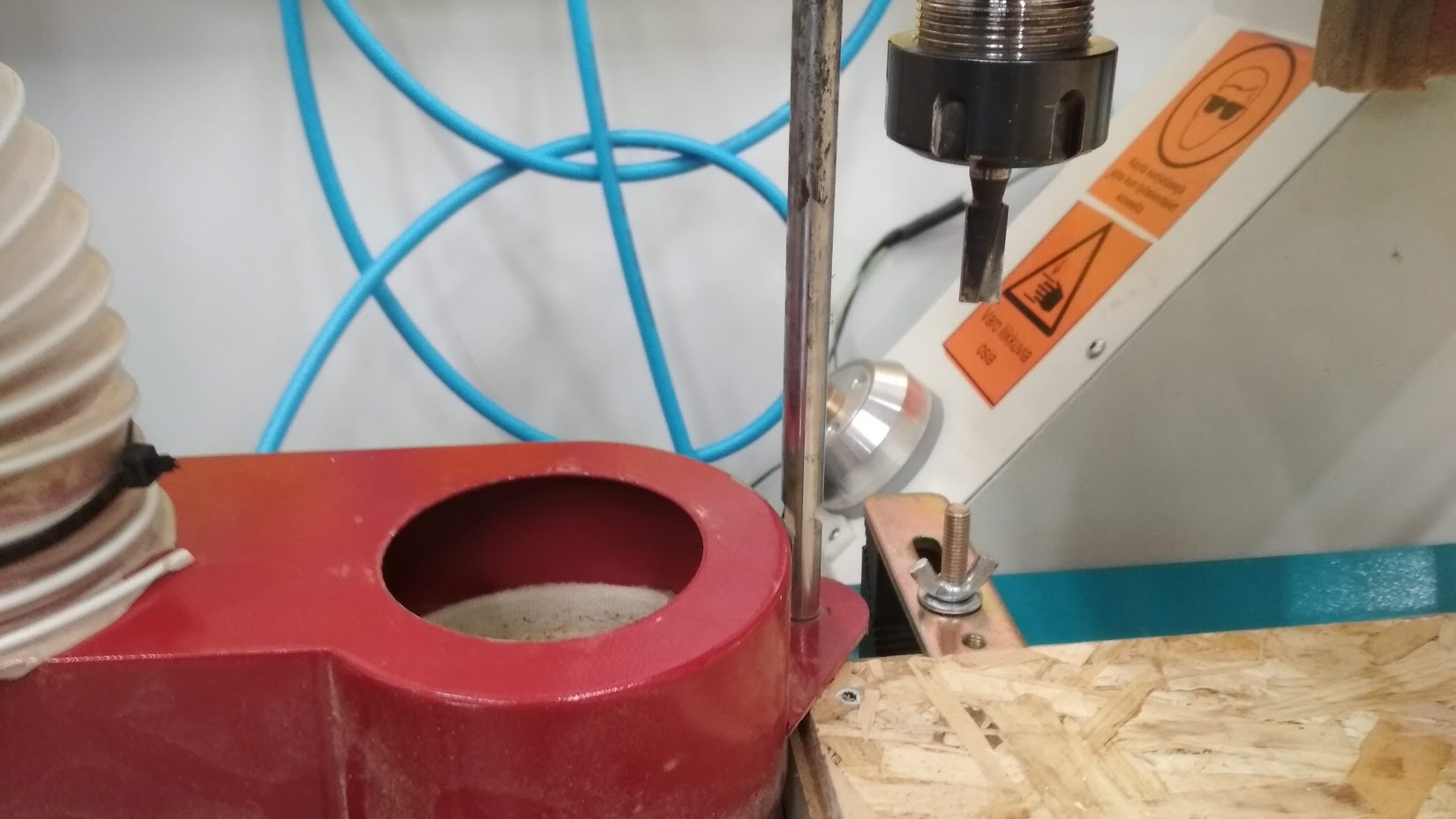
- Changing tool
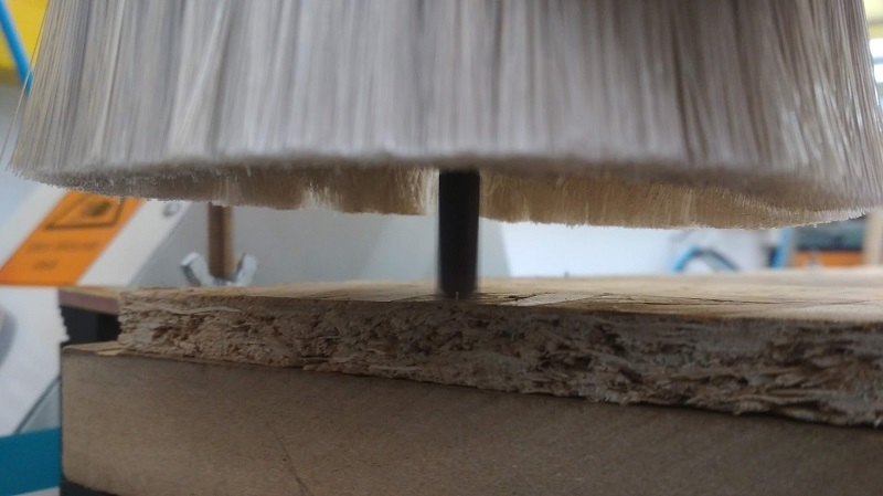
- Setting and fastening of Stock piece
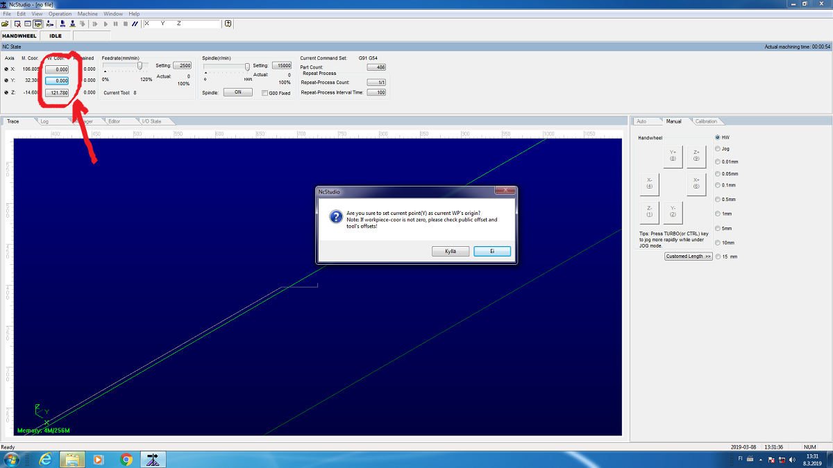
- Setting origo (X, Y, Z), Z with mobile calibrator and manually
- Loading nc code
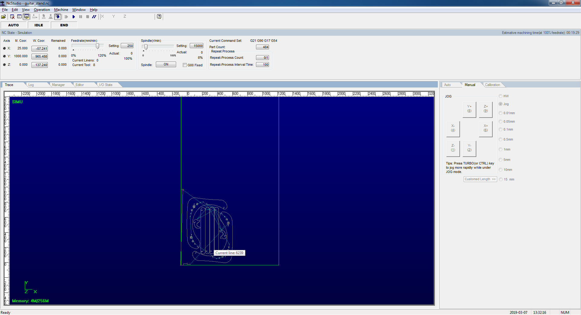
- Simulating
- Machining test model
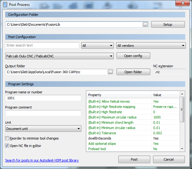
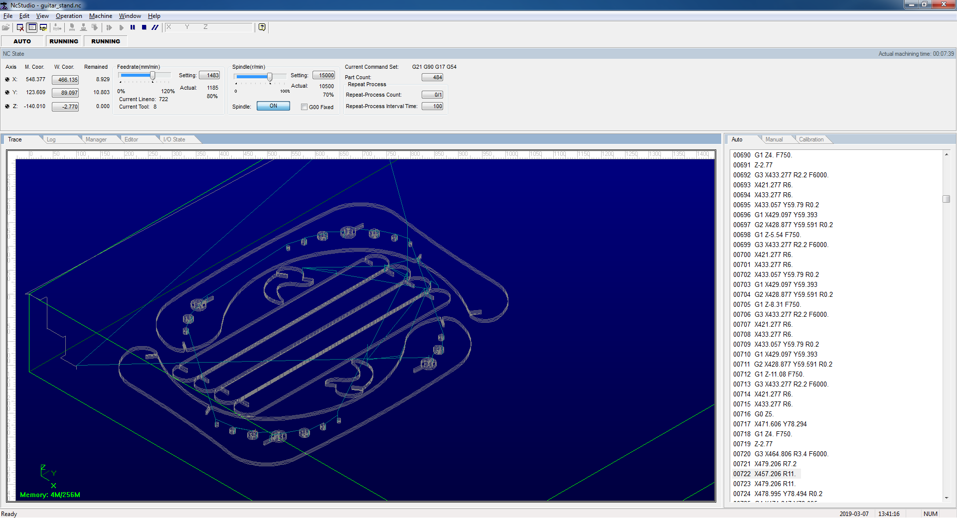
We used Fablab CNC machine and NC Studio software.
.jpg)
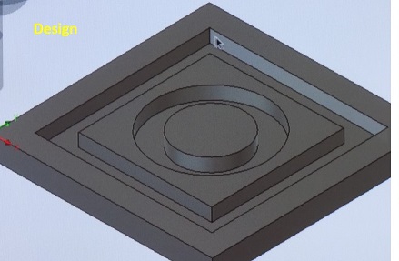
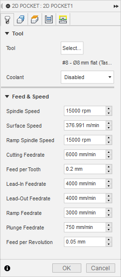
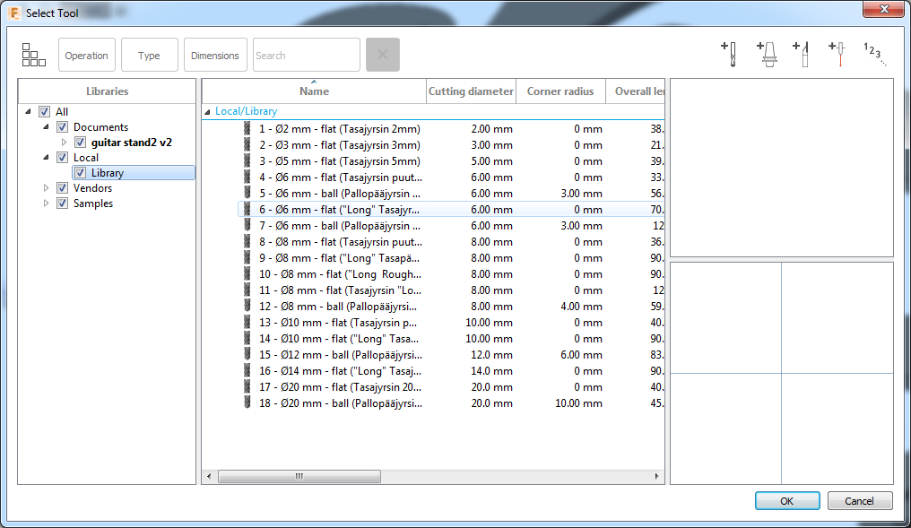
We opened the design file that supports CMC machine (NC file). We connected the flat milling bit of size 8 mm, the feed rate was 80% of the maximum 6000 mm/min to 4800 mm/min. Spindle speed is 80% of the maximum 15000 rpm-12000 rpm. We chose the board for cutting and fixed it on the table with screws. We set the Z origin both manually and automatic to the learn the process. XY position was set to zero avoiding screw region.
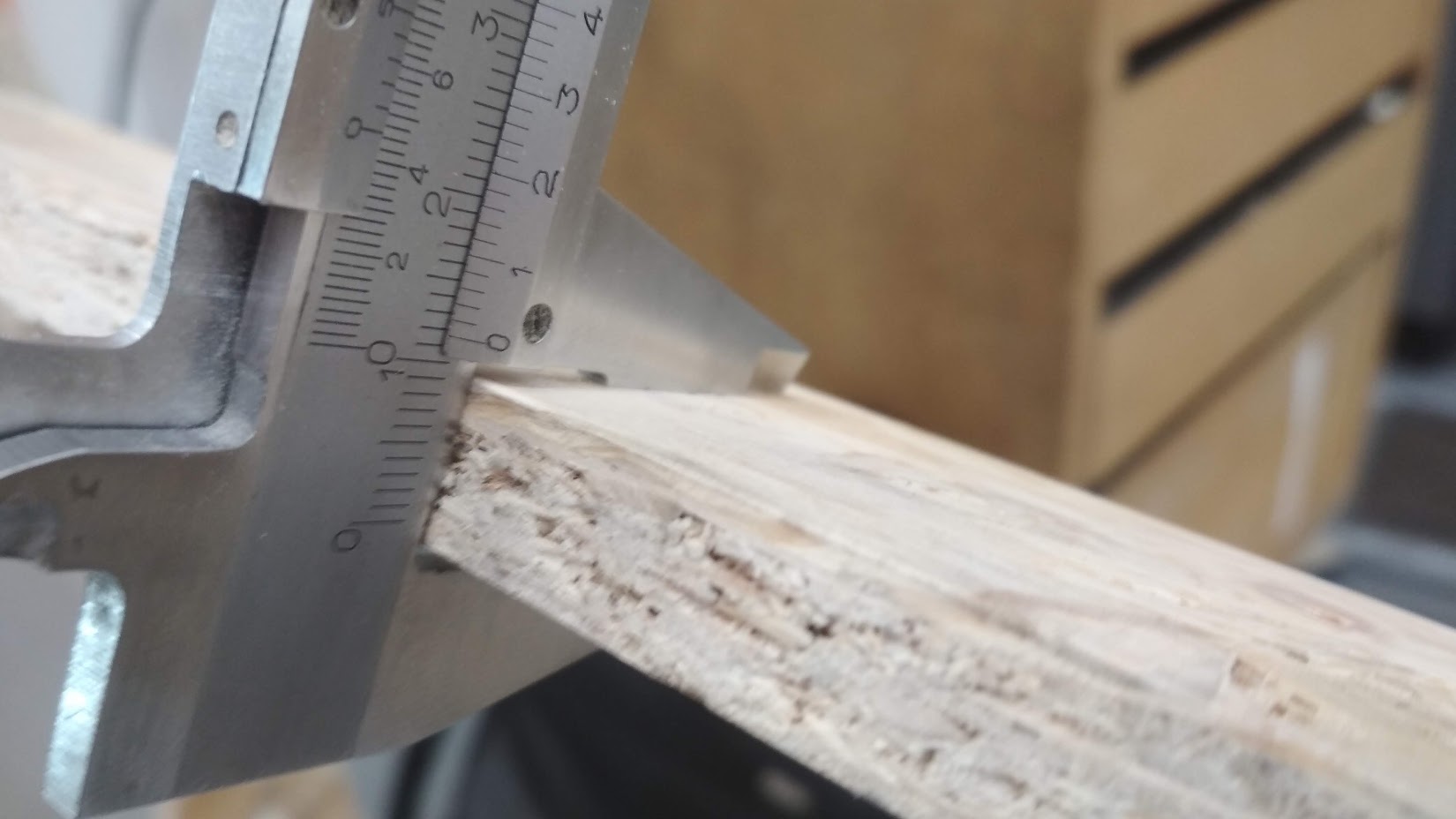
Cut piece and measuring.
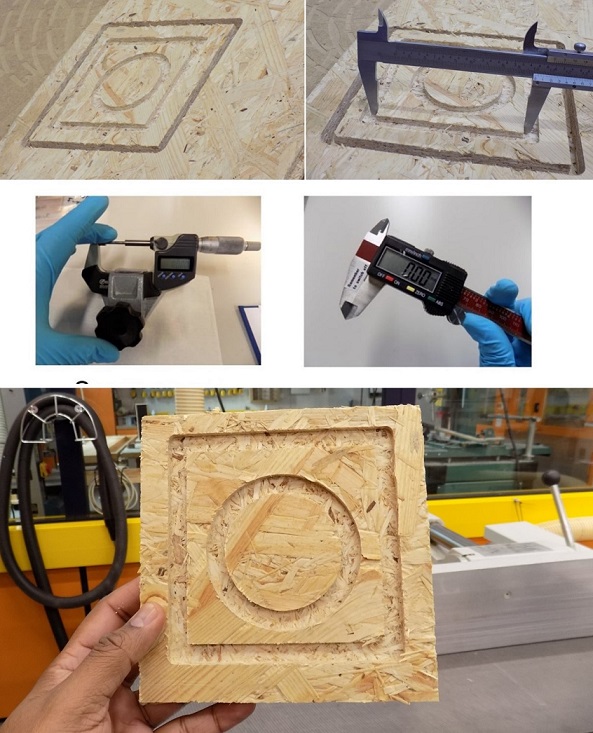
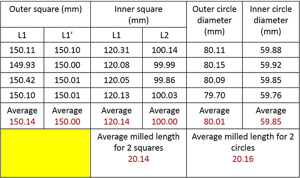
We easured the average milling length for 2 squares is 20.14 mm while the average milling length for the 2 circles is 20.16 mm. Both values are close and error is minimal in comparison with the 3D design file.
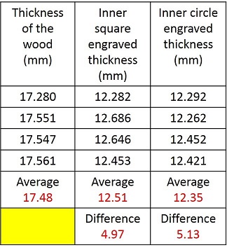
We also documented the engraved area from the square, and circular engrave thickness measured before and after milling using digital screw gauge. See the results and difference in thickness from the square area and the circular area from the below table.
2. Model
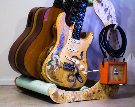
Task: Make something big on a CNC machine.

The idea of this project appeared about six months ago. The design was made in collaboration with my good friend and talented engineer Mikhail Lebedev. It is a press-fit guitar stand. I even cut a test version on the laser cutter from 6mm plywood. But to cut through 6mm plywood I did about 10 passes with the laser. So the kerf was terrible. I assembled it anyway, but 6mm plywood wasn't enough to make the whole construction stable. So the project was waiting for this week for a while.
|
|
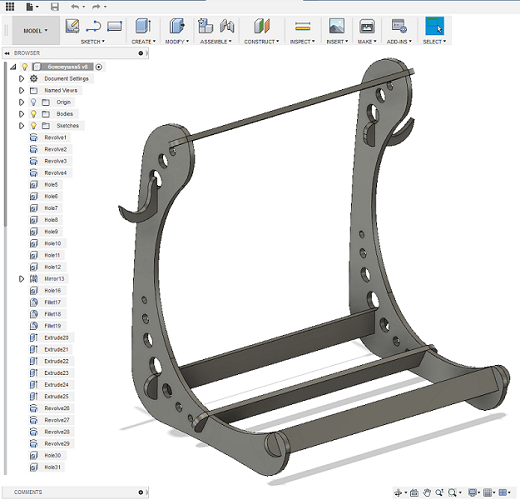
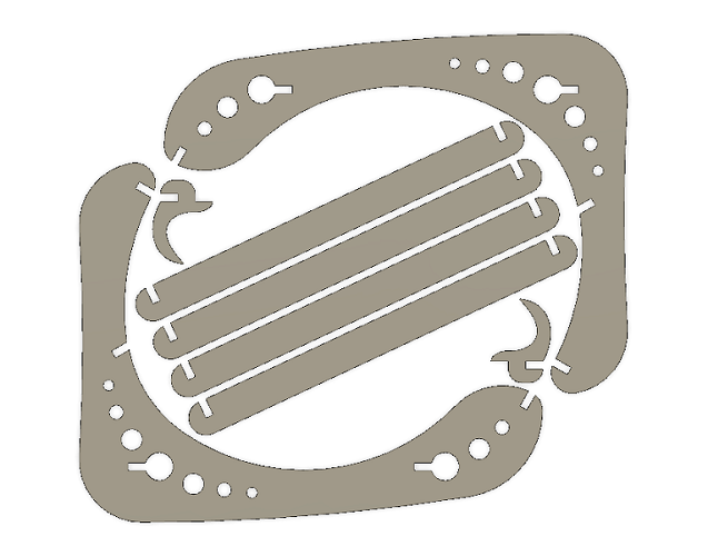
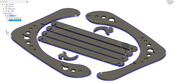
The original design was made in AutoCAD but I don't have a lisense anymore. So I imported side part into Fusion 360. I used Find Features command trying to edit the geometry. But I failed to get a sketch from it. So I Extruded geometry up to 11mm and using the Move command adjusted all joints to 11mm. We measured the thickness of the material earlier and I wanted the joints to be as stiff as possible, so I have not added any kerf number. Then I sketched a hook and a slat. Then I copied elements and Aligned them first into a model and then on one plane. And then I moved to Manufacure part.
|
|
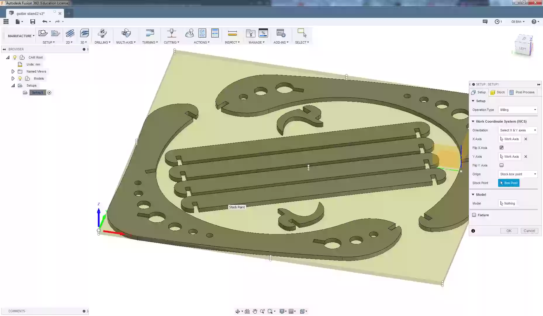
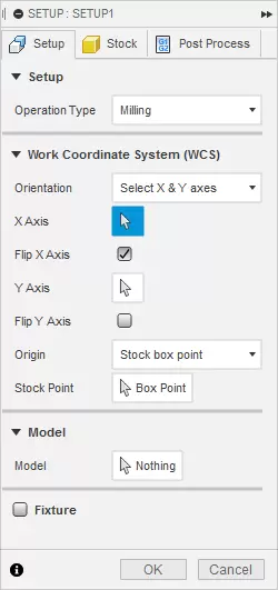
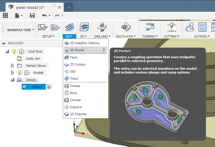
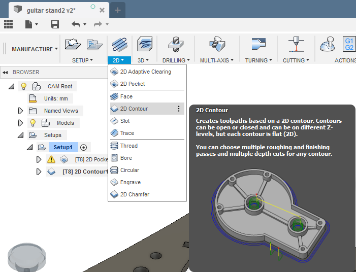
3. Manufacture
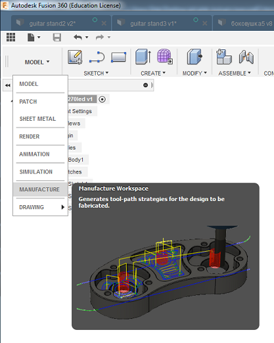
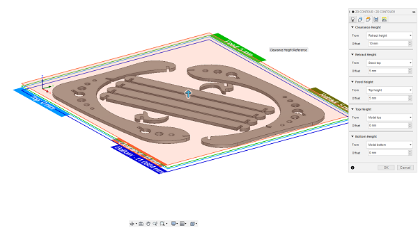
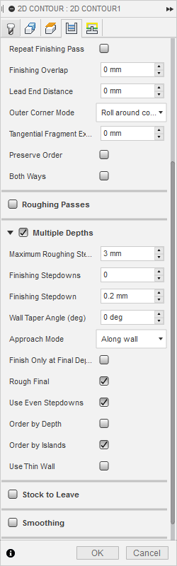
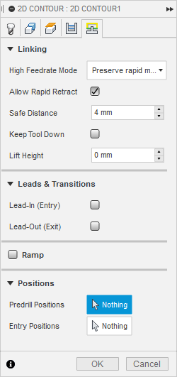
In toolbar SETUP/New Setup
|
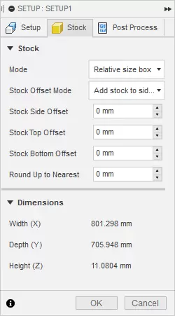
|
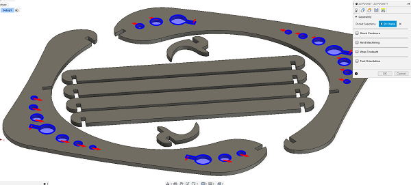
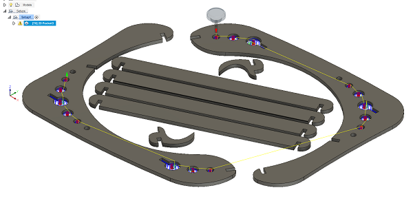
Simulation of the process. Looks nice!
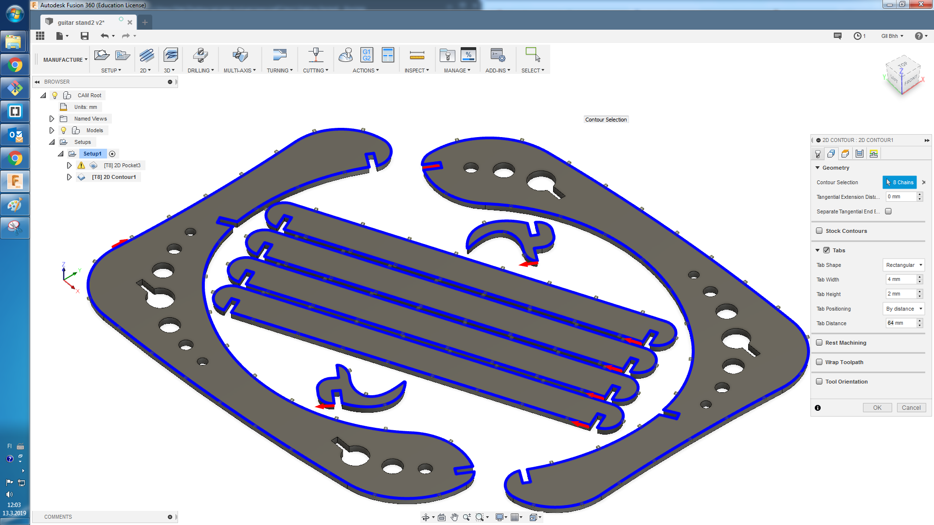
I did all the same the next day and cut another piece. I used leftovers from the material so I rearranged details on the plane. I increased tabs width a little bit.
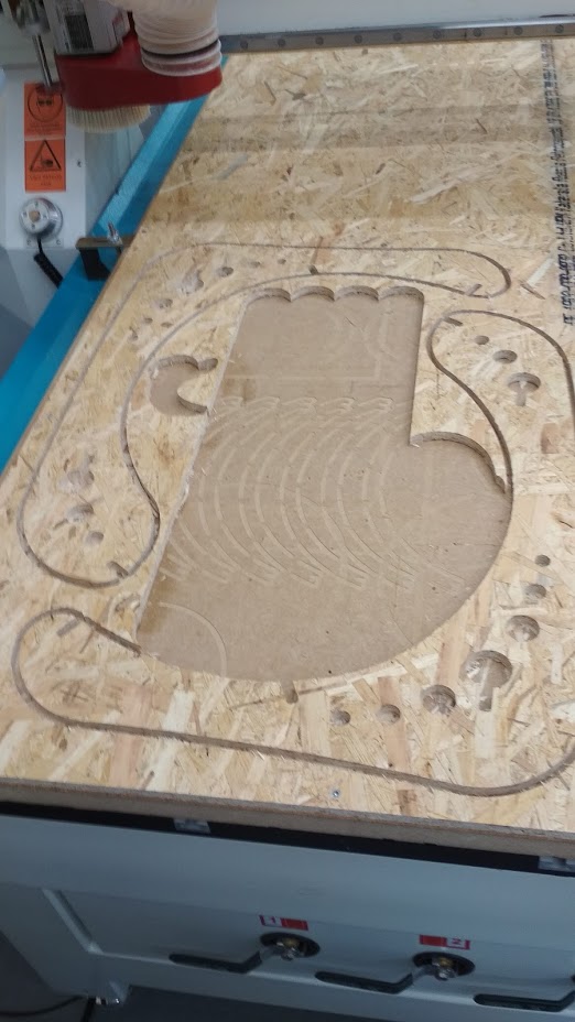
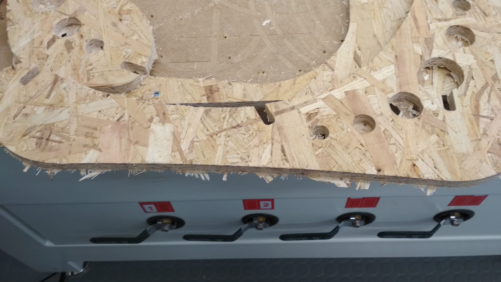
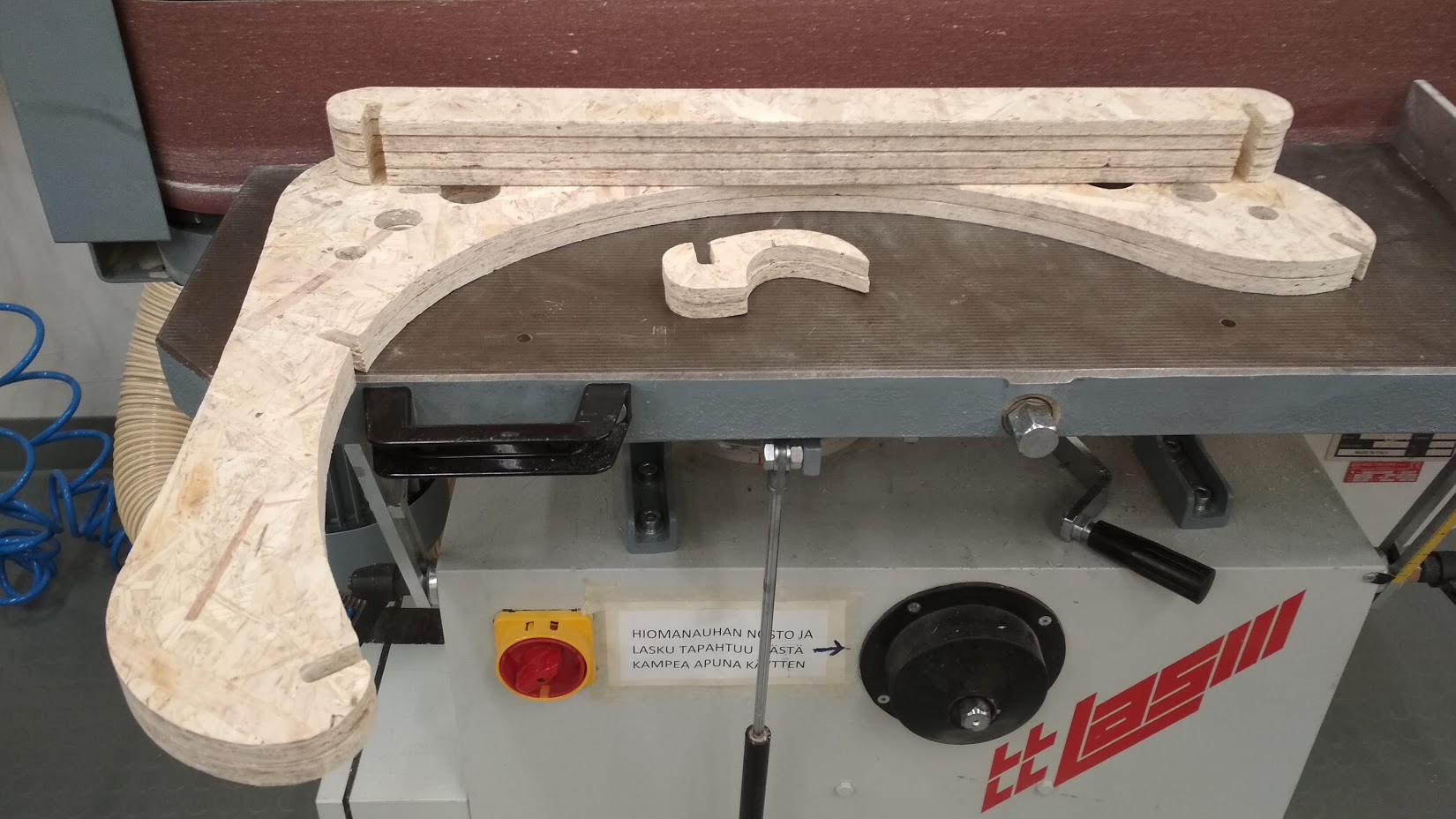
4. Machining
|
|
|
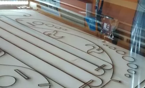
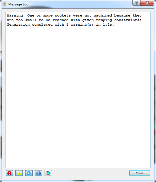
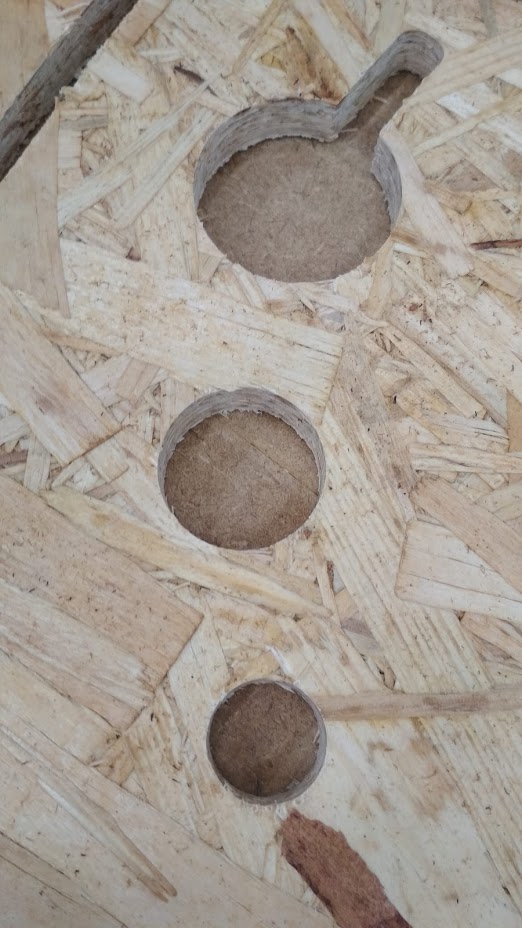
The tabs I created were too small. Because of the material structure on some parts the tabs were cut trough. So for a few times I paused the process and removed parts with a carpet knife. Pockets were cut perfectly.
|
|
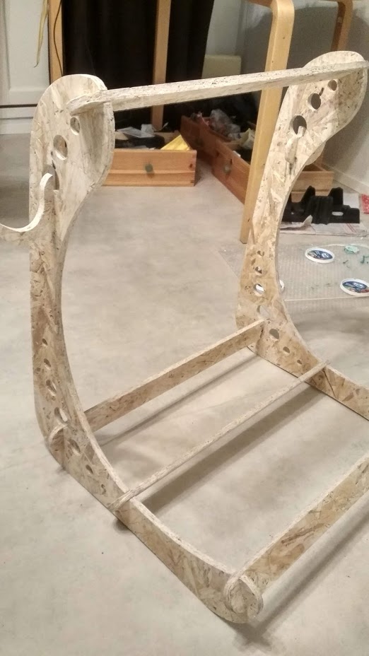
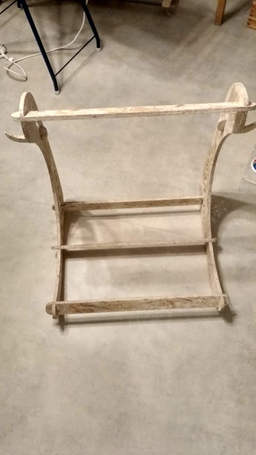
5. Results of the week
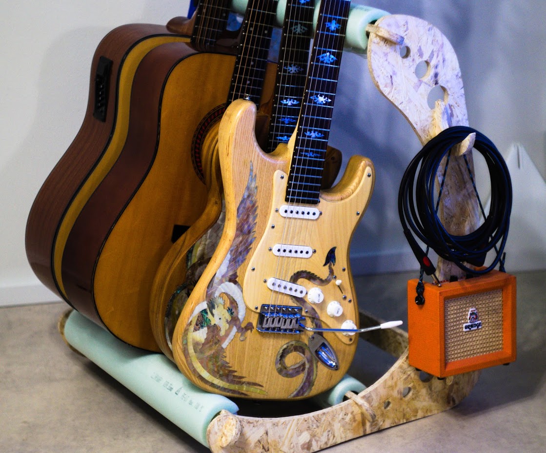
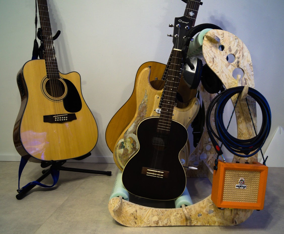
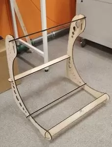
- Guitar stand project came out very nice. I'm very satisfied with the job done.
- This week I tried to use new to me image format .webp. If this test run will work I'll use it on my further assignment pages.
- The final project idea was supplemented with a few new ideas. I'll update Final Project page soon.
- Working on the feedback given earlier takes a hell of a time.
- I ordered LED-stripes for my final project.