Week assignments
- Model experimental objects/part of a possible project in 2D and 3D software
- Show how you do it with words/images/screenshots
- Includ your original design files
My 3D CAD Design
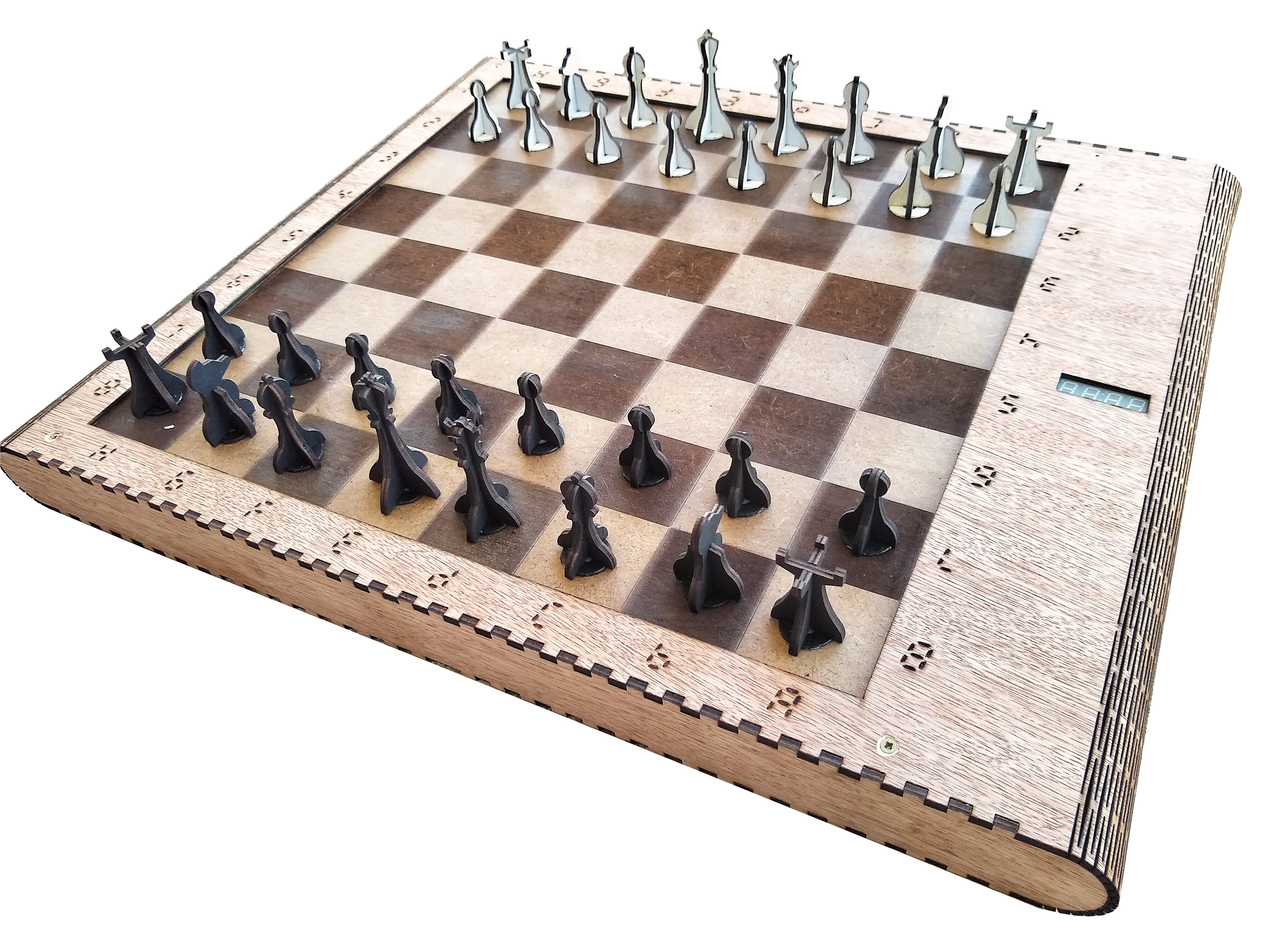
In connection with my final project I show here how I designed a pressfit-kit of my chessboard thanks to fusion360.
Step 1: Sketch and parametrize the notch
Next week, we will have to use parametric design to build our pressfit kit. So, I decided to allready parametrize my design of this week.
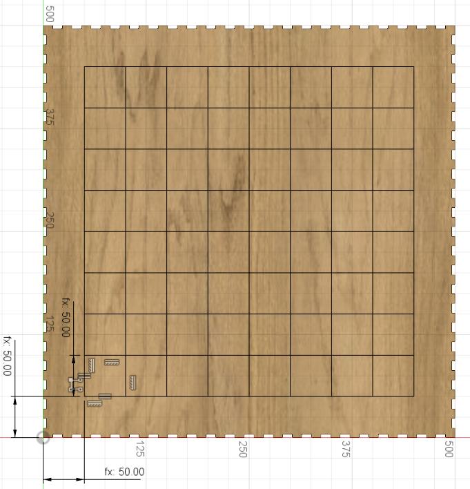
First, I defined 3 parameters as you can see in the image below.
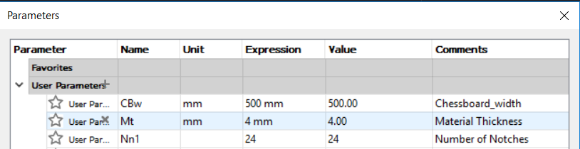
This 3 parameters will allow me to redifine my chessboard width, the thickness of the material that I will use and the number of notches that I want on the top part of my chessboard.
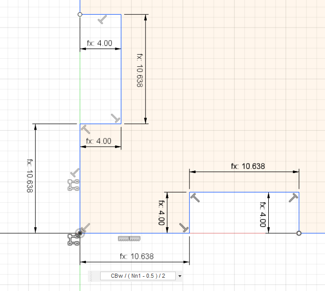
This three parameters are used in the sketch below:
- Material thickness define the deepness of a notch;
- Number of nodes and chessboard width are used in a formula to define the width of a notch.
Step 2: Replicate the notch
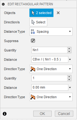
Then, thanks to the rectangular pattern tool, I can replicate my notches as many times as I need.
I do it for the four sides of the chessboard filling the parameters as shown in the picture below.
Step 3: Extrude the sketch
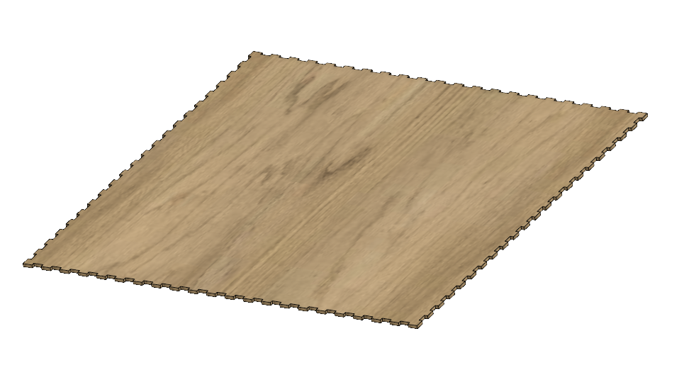
I have a closed sketch that I can extrude with the material thickness parameter. By a right click on the new body, then Appearances, I can give a plywood aspect to the bottom part of my chessboard.
Step 4: Duplicate the bottom part and draw the squares
As I want to draw the squares on my chessboard I duplicate the bottom part thanks to the move/copy options and I move it 50mm above.
I use the top plane of the new body to sketch the squares. I created a new parameter for the square size which is defined as a tenth of the chessboard width. Given the fact that there is eight rows and columns on a chessboard, this allow me to easily center the squares on my board.
Step 5: Rendering the squares
Next week, I will cut my chessboard with laser-cutter. I want to mark the white squares and engrave the black squares. To have a preview of what it will look like a proceed as follow :
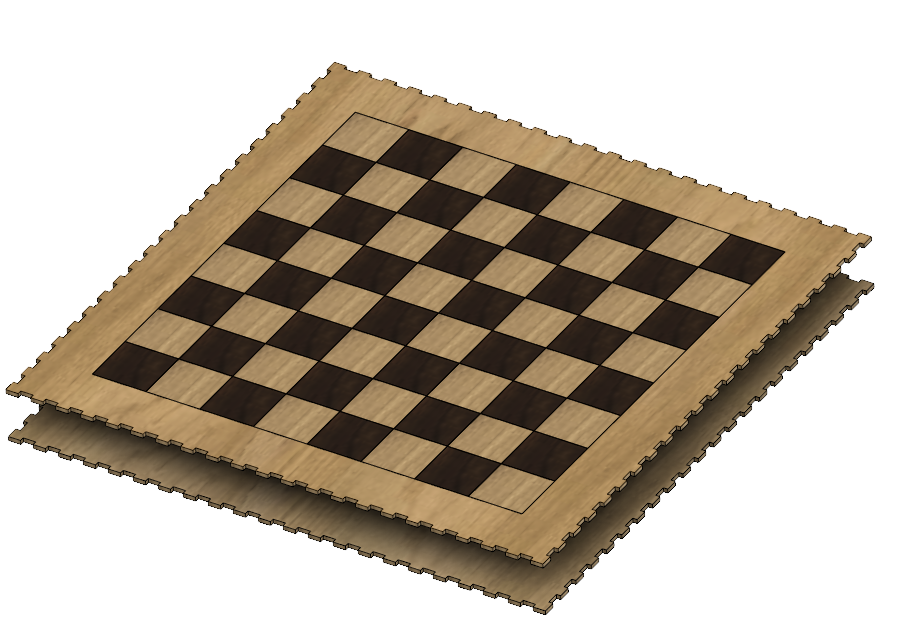
I extruded the black squares of 0.1mm to create a new body that I rendered in black. I did the same for the white squares but leaved them as ply wood only to highlight the mark of the laser.
The final render is given below.
You can find my files here.
My 2D raster CAD trials
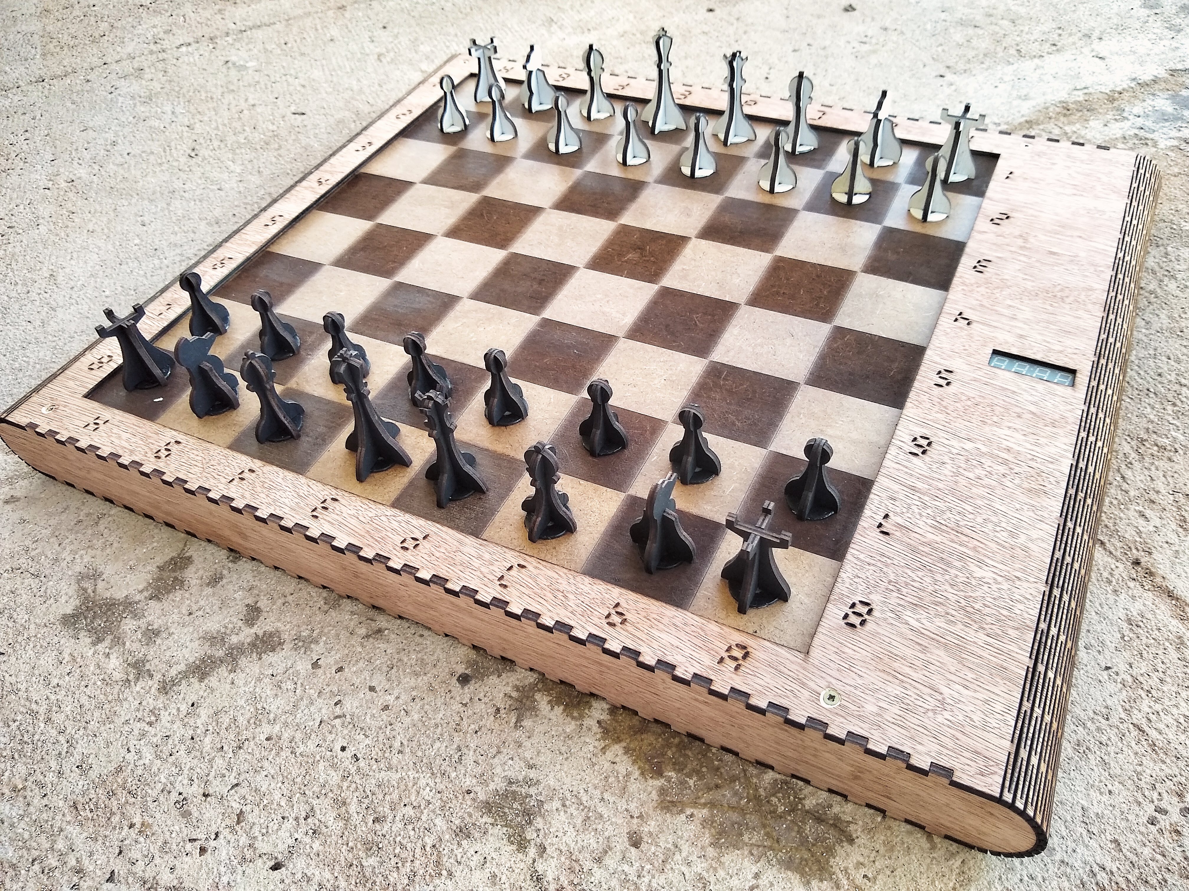
For my final project slide I have a good picture of my chessboard and I used GIMP to cut it out.
I used the smart cisors to remove the background, adding point where the engine couldn't guess the limits and correcting the stroke when it went into the chessboard.
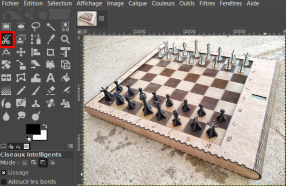
And here is the result of the cutout:
My work on a 2D vector software
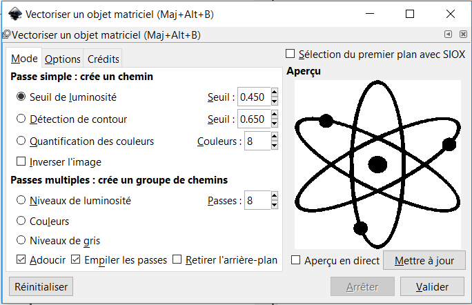
On week 4 I worked on Inkscape and here is a copy of what I did on this project.
I really like the big bang theory TV show. This is why I decided to cut the logo of the show. I found this image on internet. I have to resize it and modify it. Since I want to still be able to see the brand of my computer, I had to delete the point at the middle and find the good dimensions for the lines not to cross the brand.
![]()
Working in Inkscape
First I had to vectorize the picture:
Then I had to separate the different elements to be able to remove the central point.
![]()
And finaly I resized the logo that you can find here.