Summary
- Resign the hello world board
- Creat New Project & Sketch KICAD
- Import Fab Library
- Import Components
- Connect Components
- Give Compoents correct name and value
- Annotate the design
- Assign Footprint to Symbols
- Generate Netlist
- Open Pcb New
- Read in Generate netlist
- In Pcb New Set Design Rules (Setup -Design Rules)
- Rearrange Components and Make Traces
- Place your Auxillary Axis
- Plot Layers
- Flatcam
- Tool dia 0.4
- Cutz -0.2
- Travel Z 2
- Feedrate x y 0.3
- Feed rate z plunge 0.5
- Spindle speed 12000
- Cutout tool 0.8
- Margin 1.5
- Gapsize 0.15
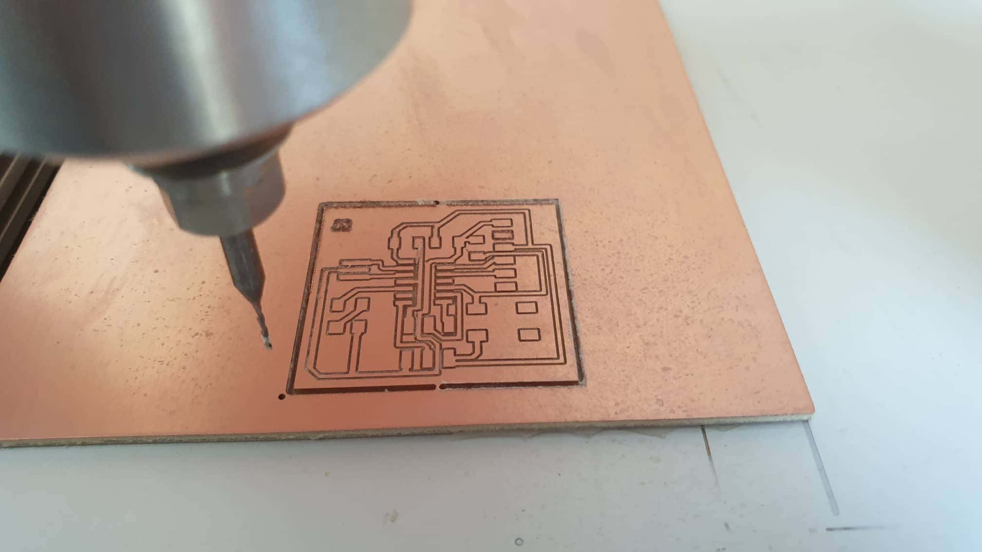
- Milling the PCB
- File formatt Inver z axis
- Coordinates- origin of coordinates
- Mis. Params-Zero Point
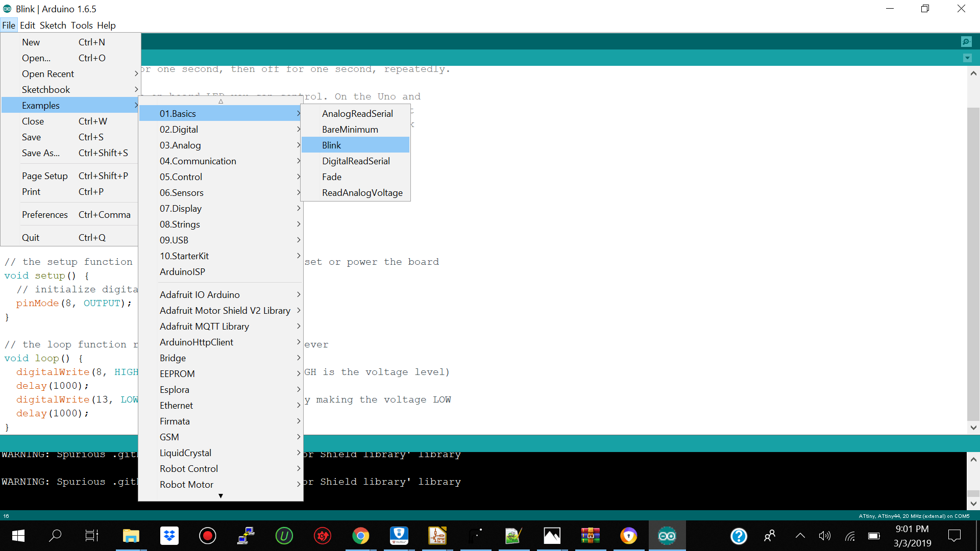
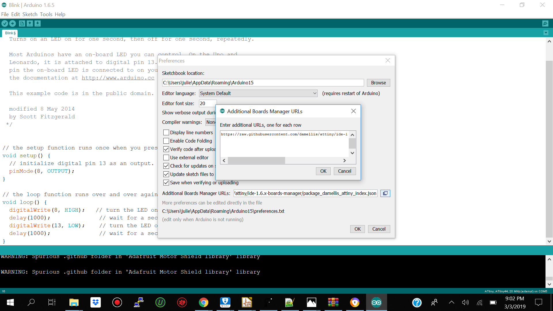
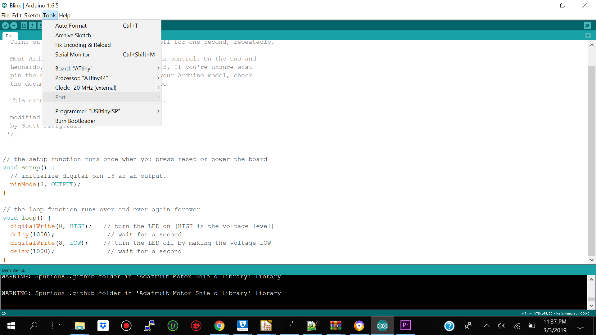
- Programming the Hello World Board Using Arduino Ide
Redesign the echo hello-world board
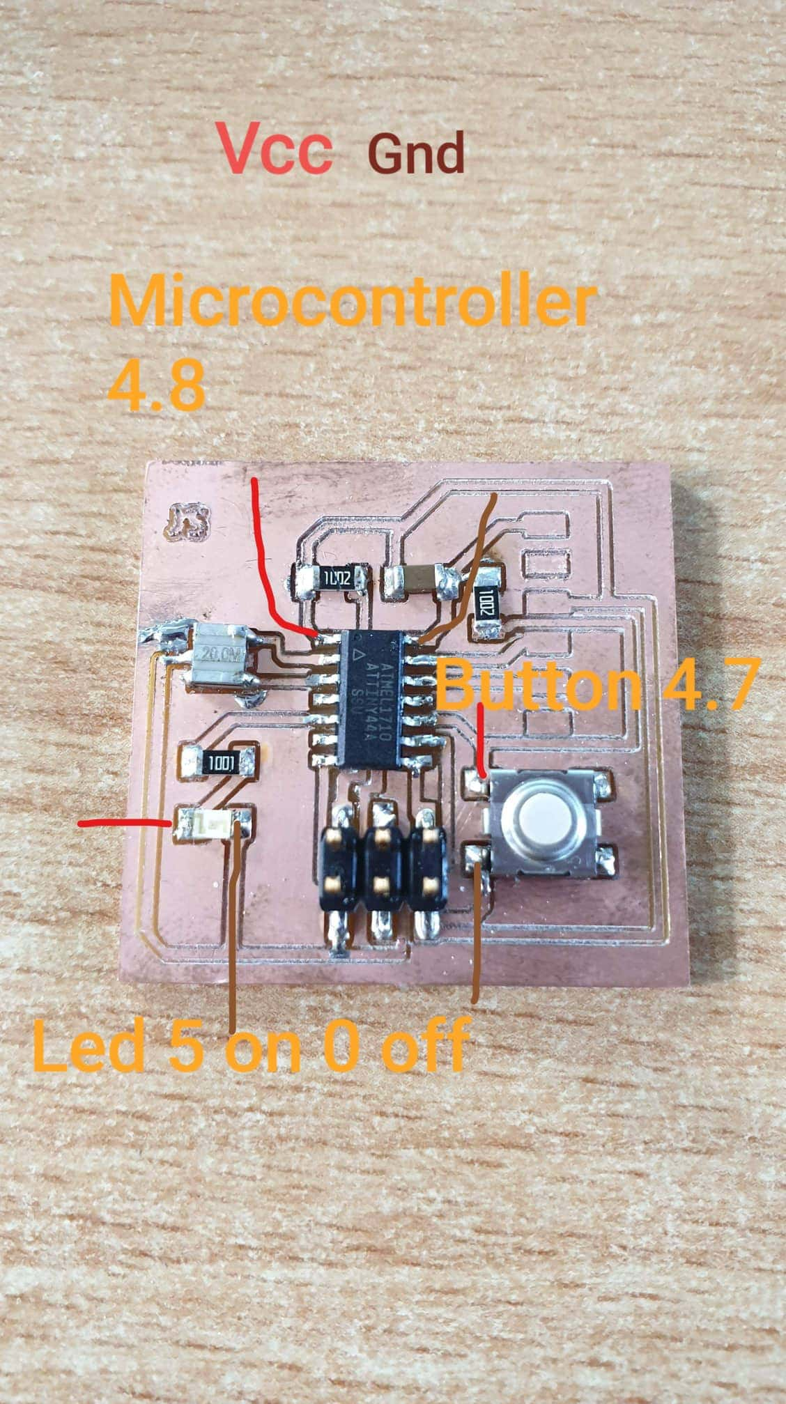
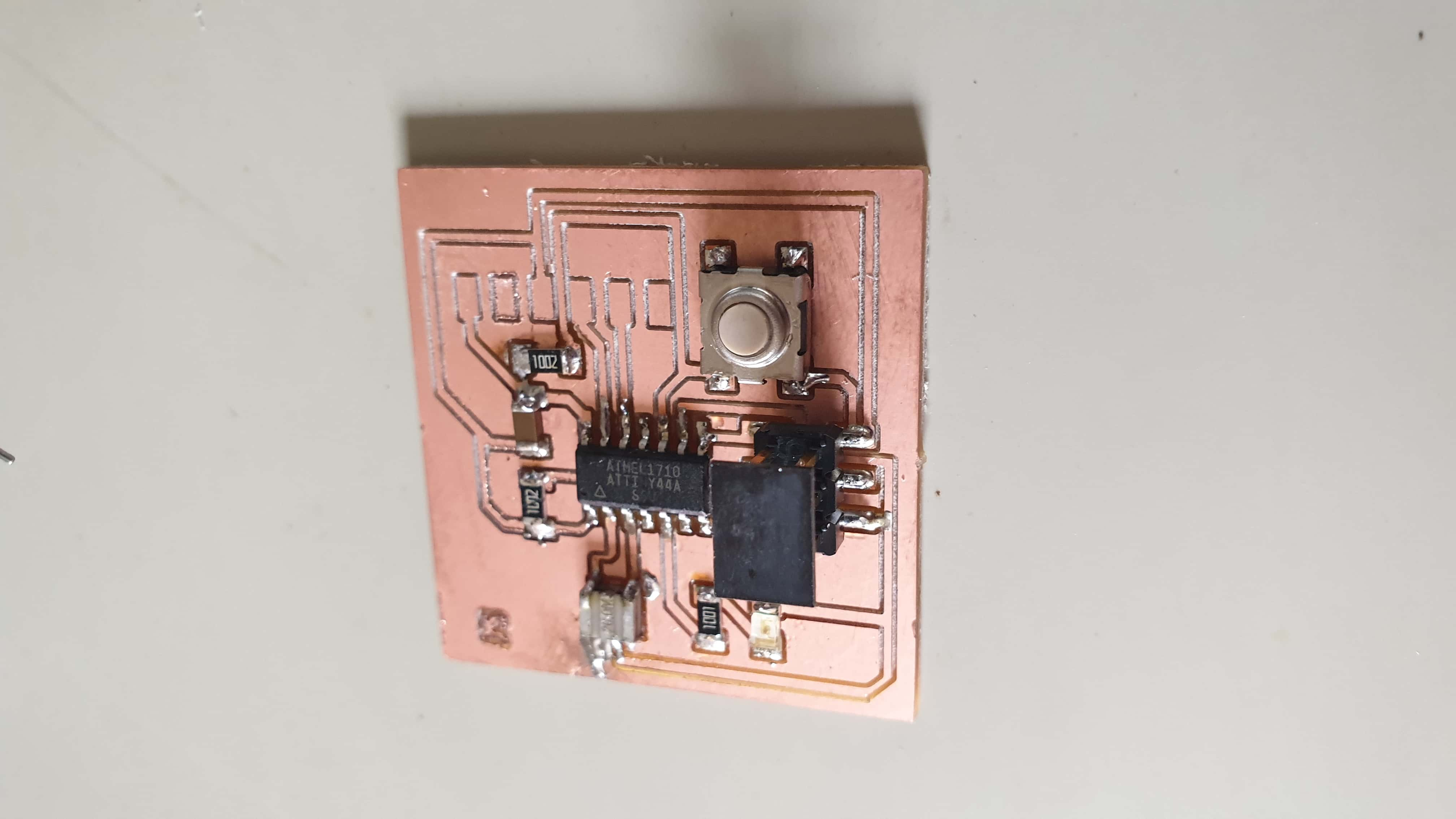
The first thing which we had to do was to redesign the Hello world board and add a led and a button. You can find the link to the board here from fab academy site.
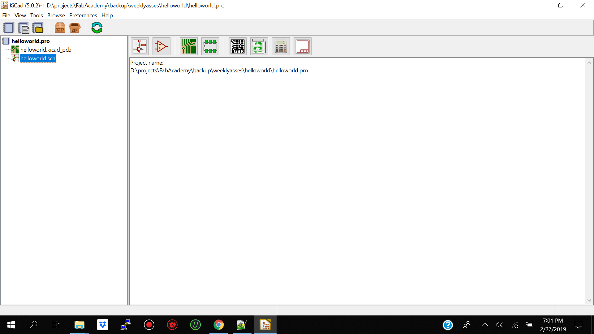
The software which I used was kicad for windows.I started off by making a new project and named it hello world then I selected New --Sketch to make a sketch of my new project.
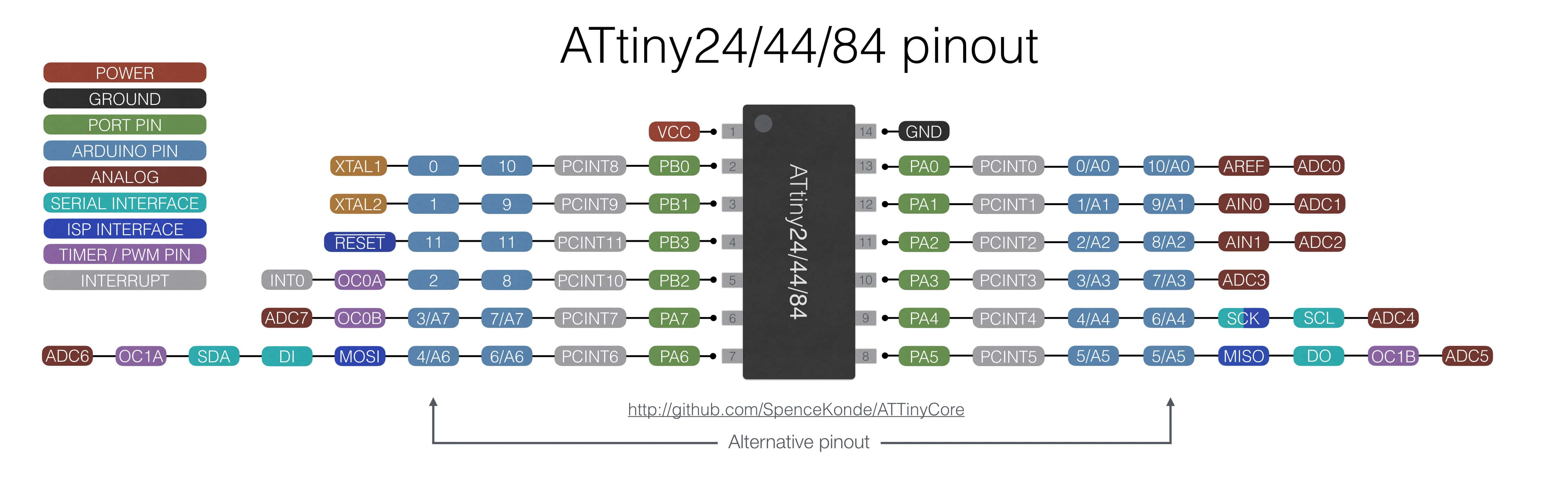
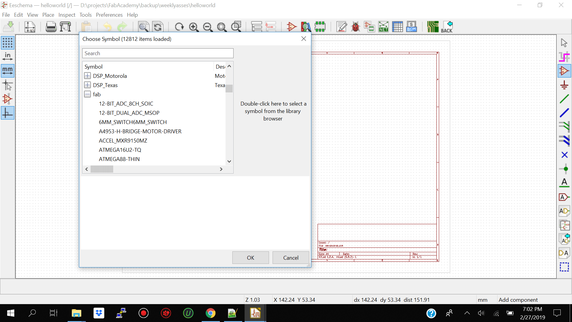
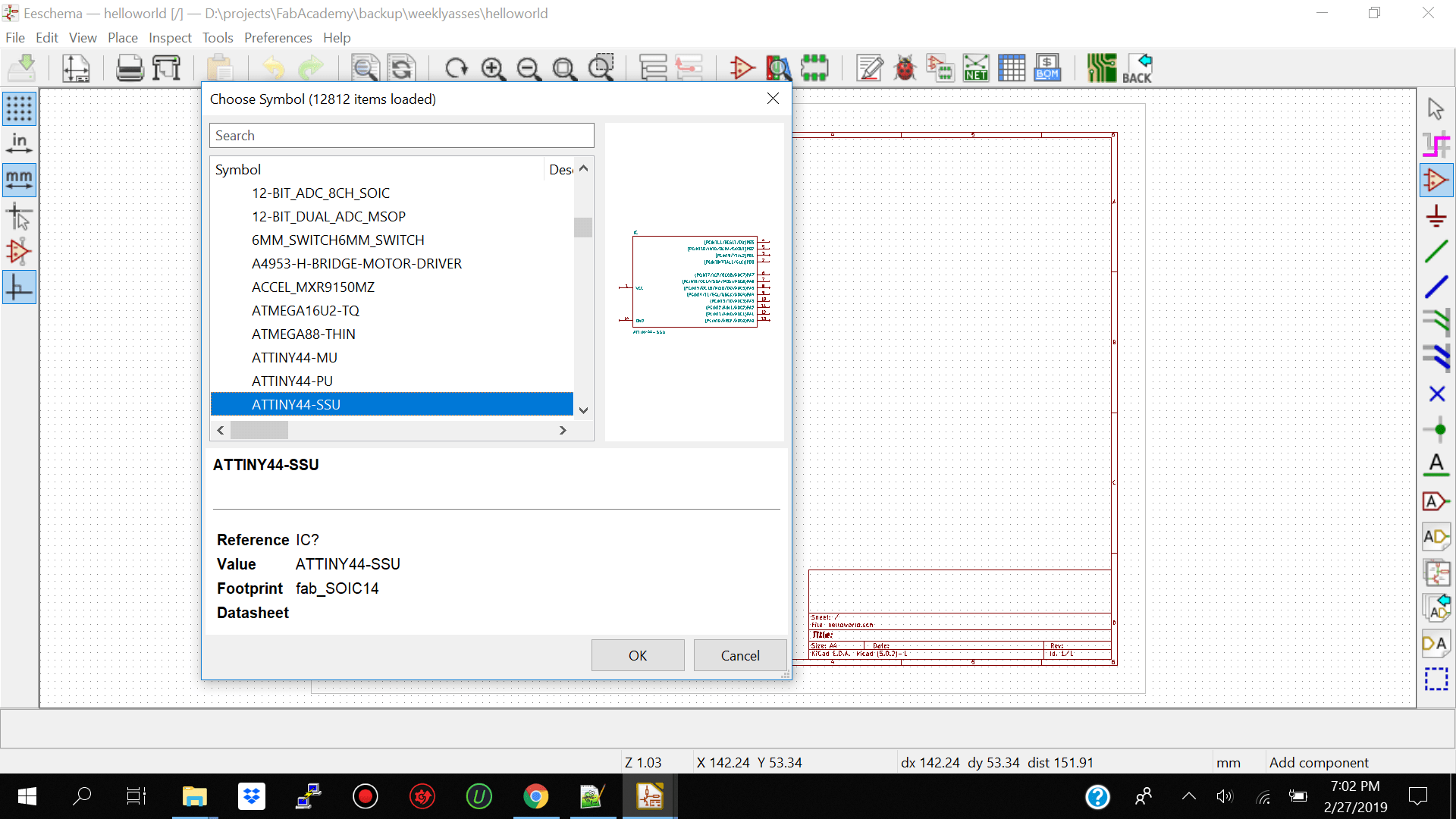
I then went ahead and added my components to my sketch by clicking on the place symbol icon on the right of the workspace. The first component which I searched for was the microcontroller atiny 44a. Before being able to find the correct components from the list you need to head to fab academy site HERE and download the libraries and add it to kicad. After you have your libraries added you scroll down and search for fab folder and inside that folder you will find the correct components by name and size for this assessment.
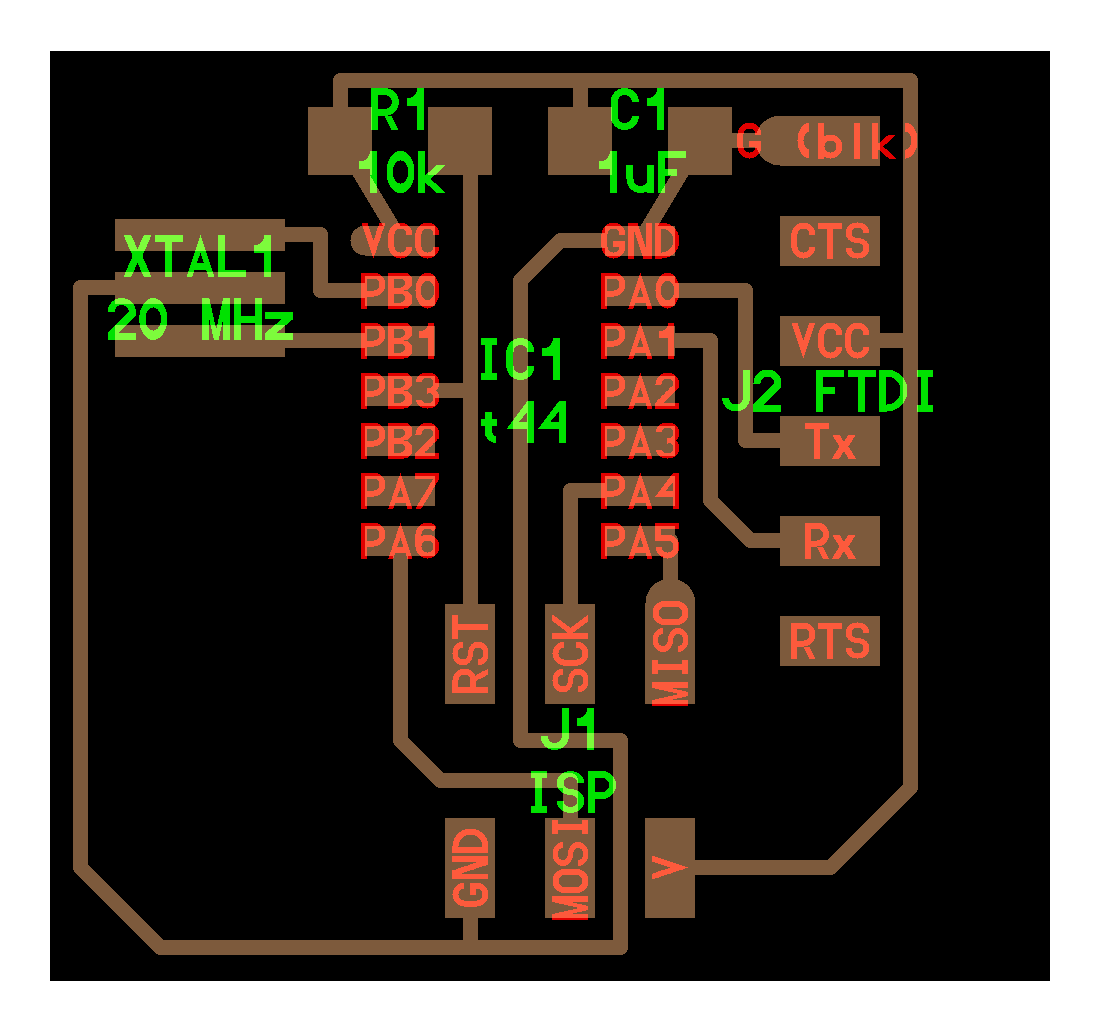
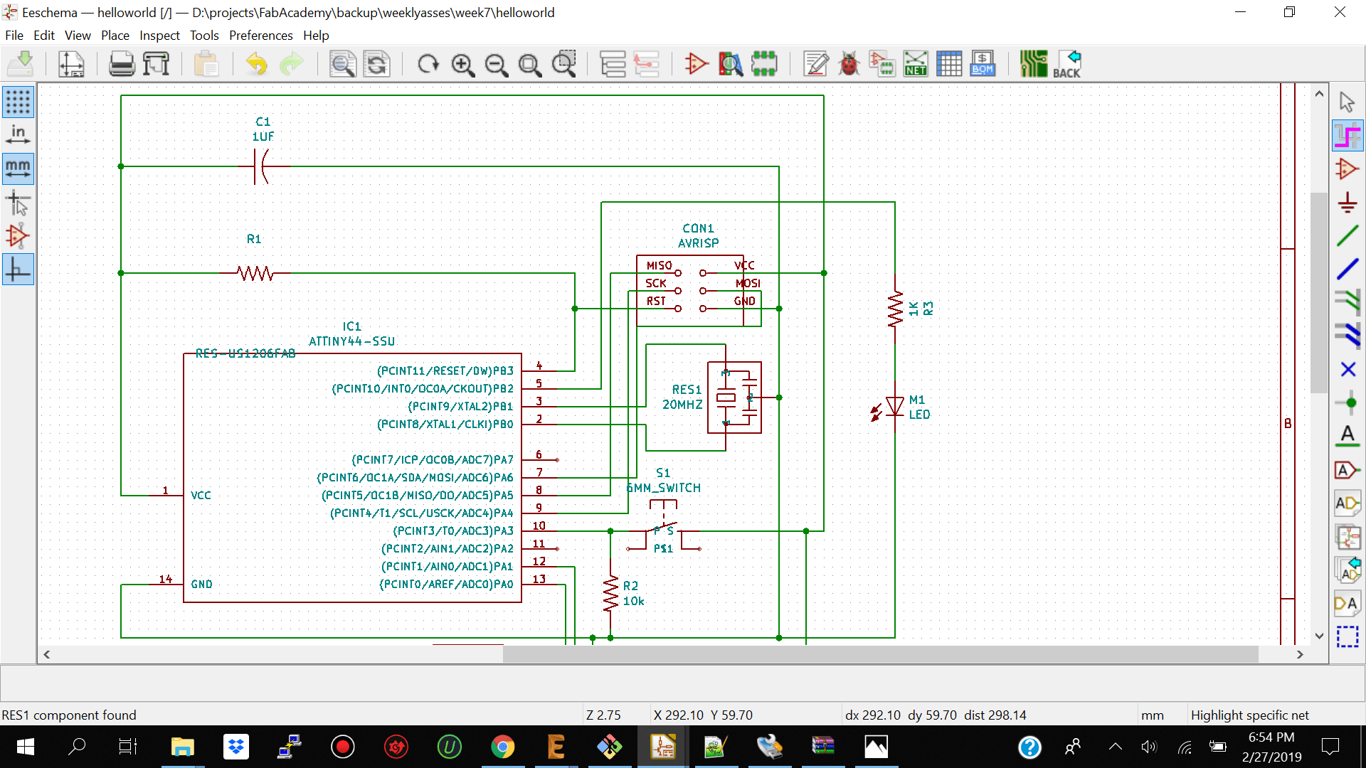
I then went ahead and added the other components from the hello world board and used the place wire tool to make my connections. I also labeled my components according to the sketch by right clicking on the names and selecting edit value. See below the components list
2x10k Ohm Resistors
1x 1k Ohm Resistor
1x Attiny44a Microcontroller
1x Resonator 20 MHZ
1x Avr Isp Connector
1x 6x 1 Pin Connector
1x 1uF Capacitor
1x 6mm Switch
1x Led green
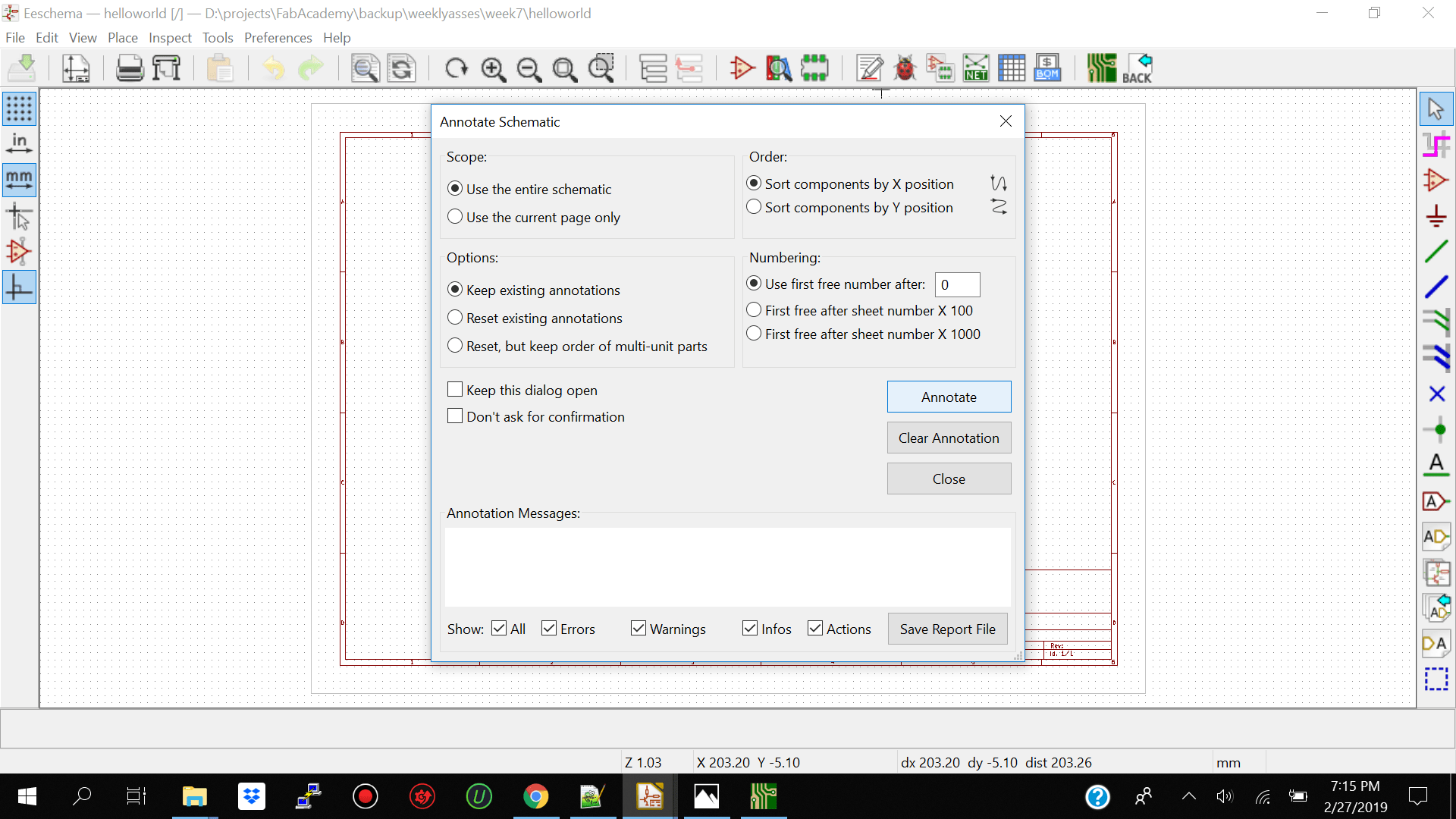
I then went and check if my components were labeled correctly by clicking on annotate schematic symbol and clicking on annotate.
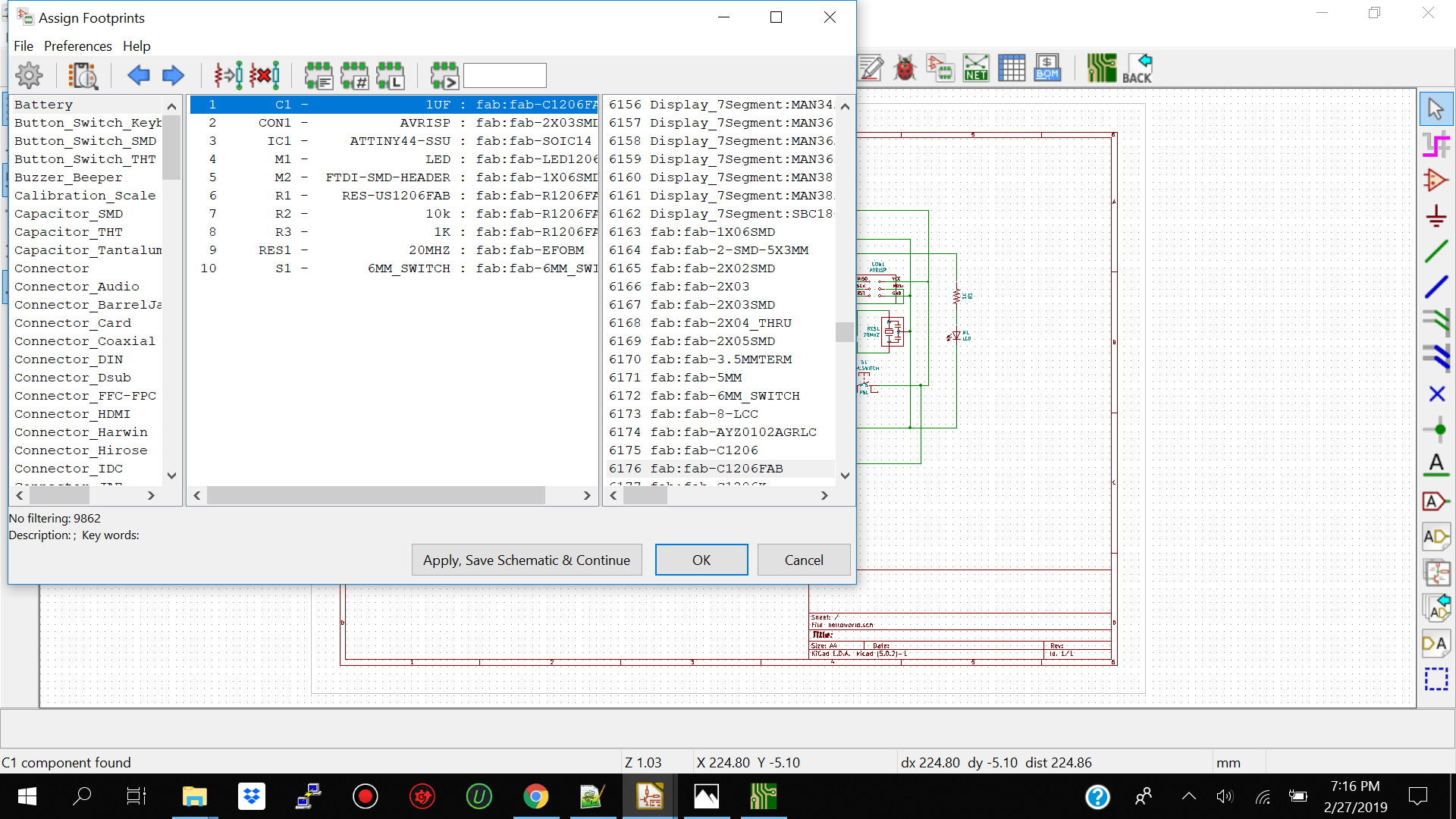
I then went and assigned my pcb footprints to my schematic symbols with the assign pcb footprints to schematic symbols icon on top of the menu.note: make sure to navigate to the fab folder to get the correct footprints.
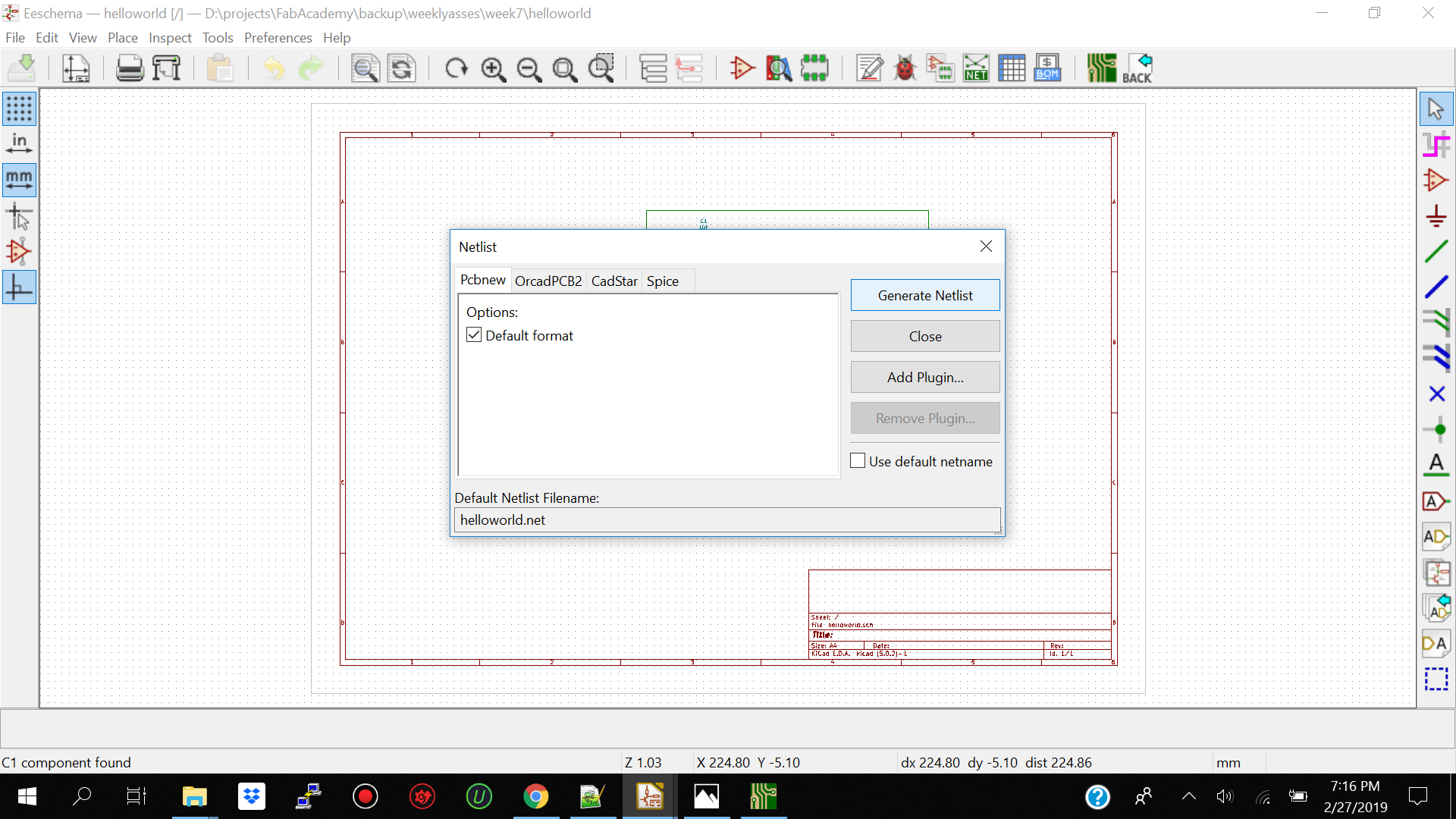
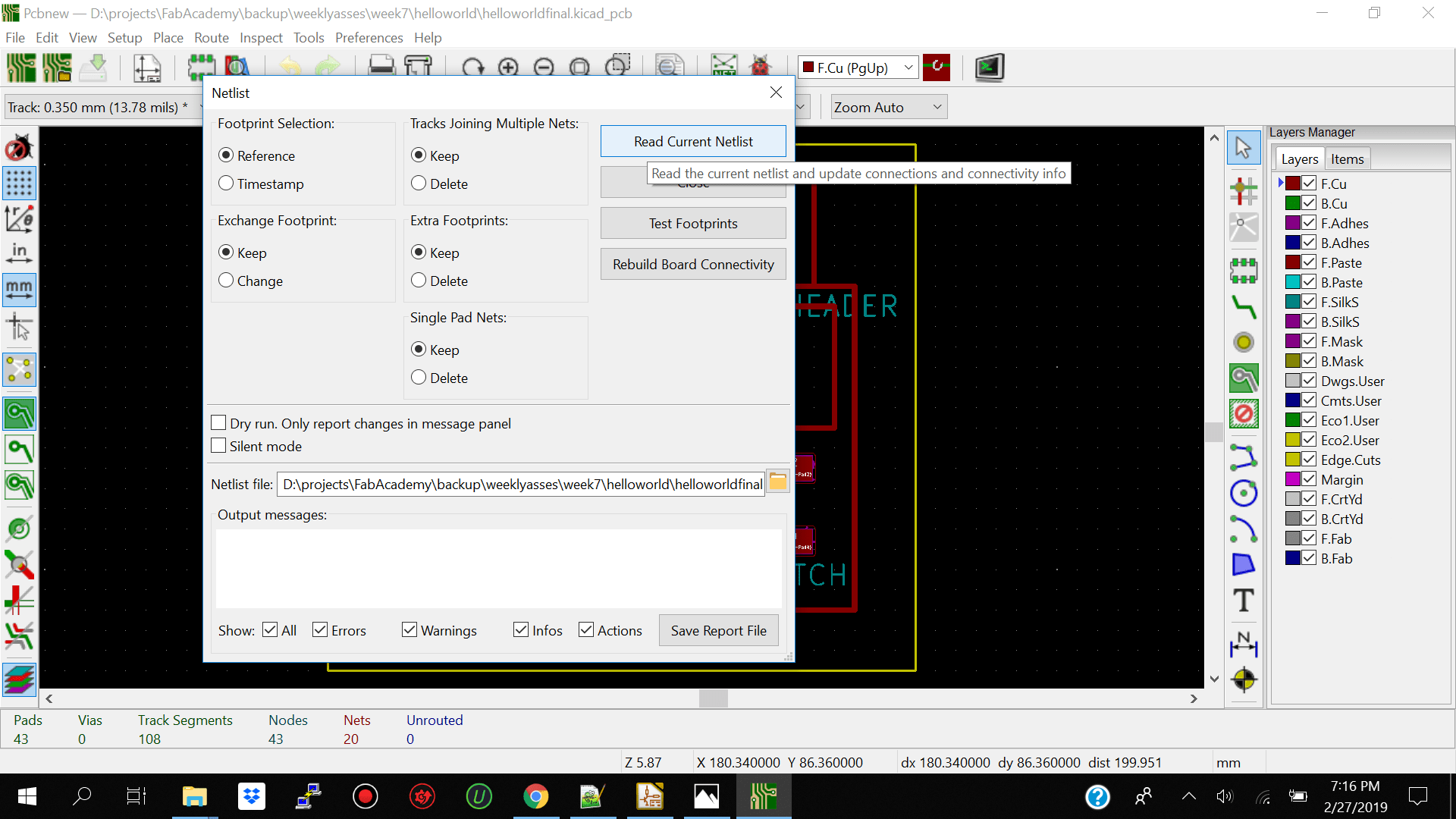
After generating the footprints correctly I went ahead and generated my netlist my clicking the generate netlist tab on the menu on top. I then clicked on the PCBNEW icon to open the new window to import the netlist and I clicked on read netlist above to read the netlis into the window.
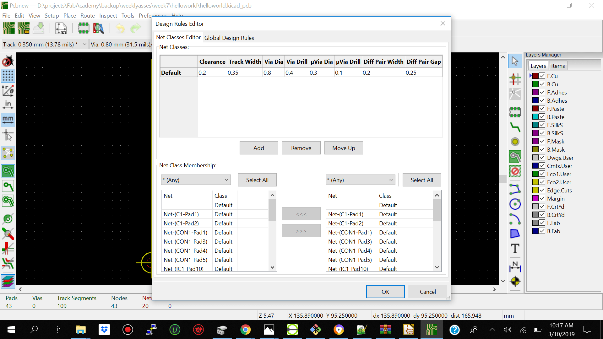
I then went ahead and adjusted the design rules.I adjusted the clearance to 0.2 and track width to 0.35.
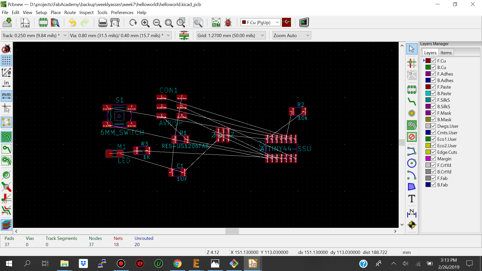
I then arranged my components to match the hello world board. I started off by putting aside the led resistor and pushbutton and arranged the other components to match the hello world board as much as I could.I then went ahead and made the tracks for my routes to connect my components correctly by selecting the rout track menu item and making the connections. Note: The rout tract menu item highlights where you should make your routes so it’s quite straight forward you just have to make sure you dont make your routes too close to each other
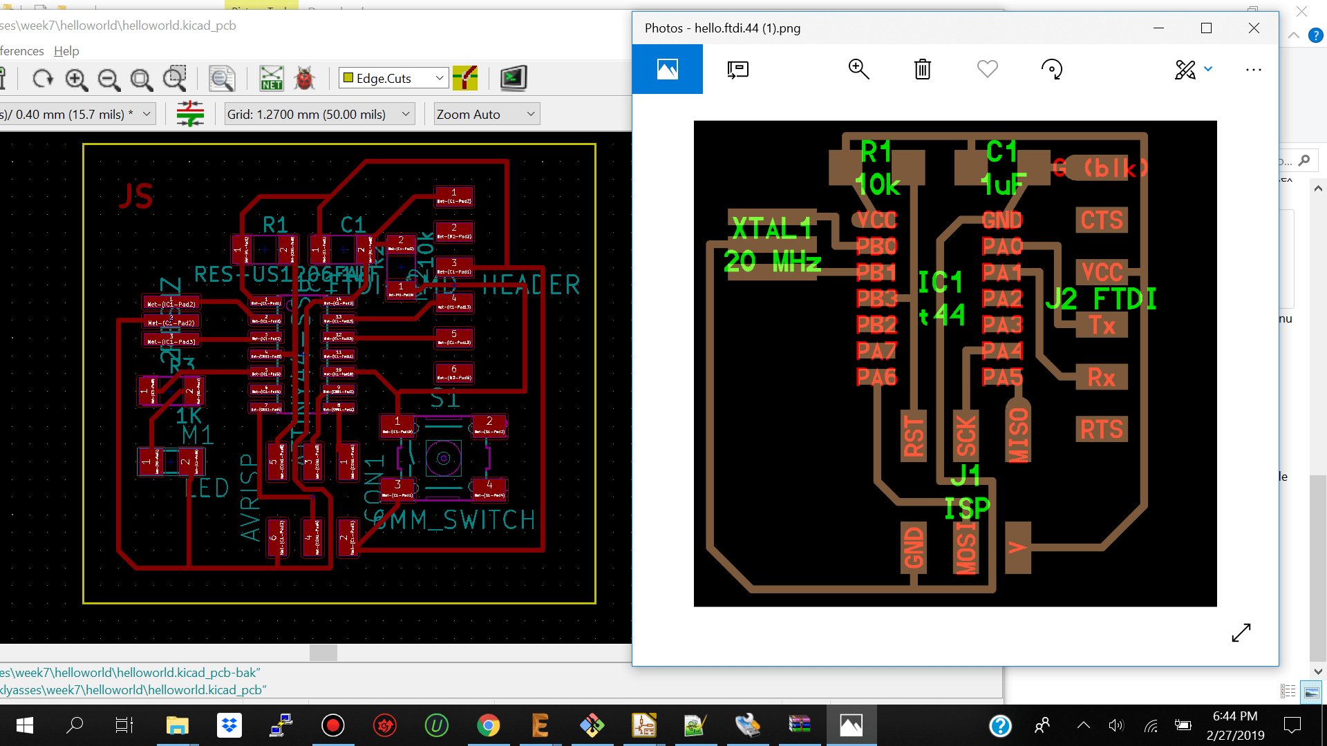
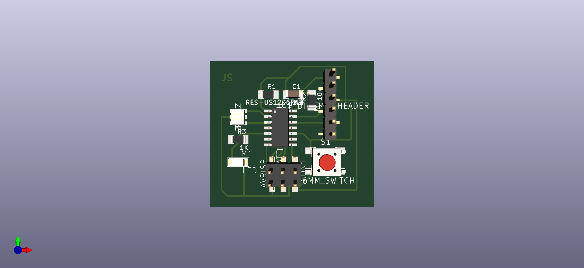
For the fun of it I added the 3d view components to my board and previewed it to see what it would actually look like.I had to double click on my component and add 3D component and search for the right component from the 3d folder.It was abit tedious because we had to manually search for each component and match it by name. For viewing your board in 3d view just navigate on top of your worspace menu and click on 3D Viewer
I then went ahead and exported my sketch and imported it into flatcam to give it the correct parameters to be read by the stepcraft cnc machine. The parameters which I used are below.
| Flatcam |
Selected |
| Tool Dia |
0.4 |
| Cutz |
-0.2 |
| travel Z |
2 |
| End Move Z |
2.0000 |
| Feed-Rate-X-Y |
0.3 |
| Feed Rate Z Plunge |
0.5 |
| Reed Rate Rapidals |
3.0000 |
| Spindle Speed |
12000 |
| Flatcam |
Cutout Tool |
| Tool Dia |
0.8 |
| Margin |
1.5 |
| Gap Size |
0.15 |
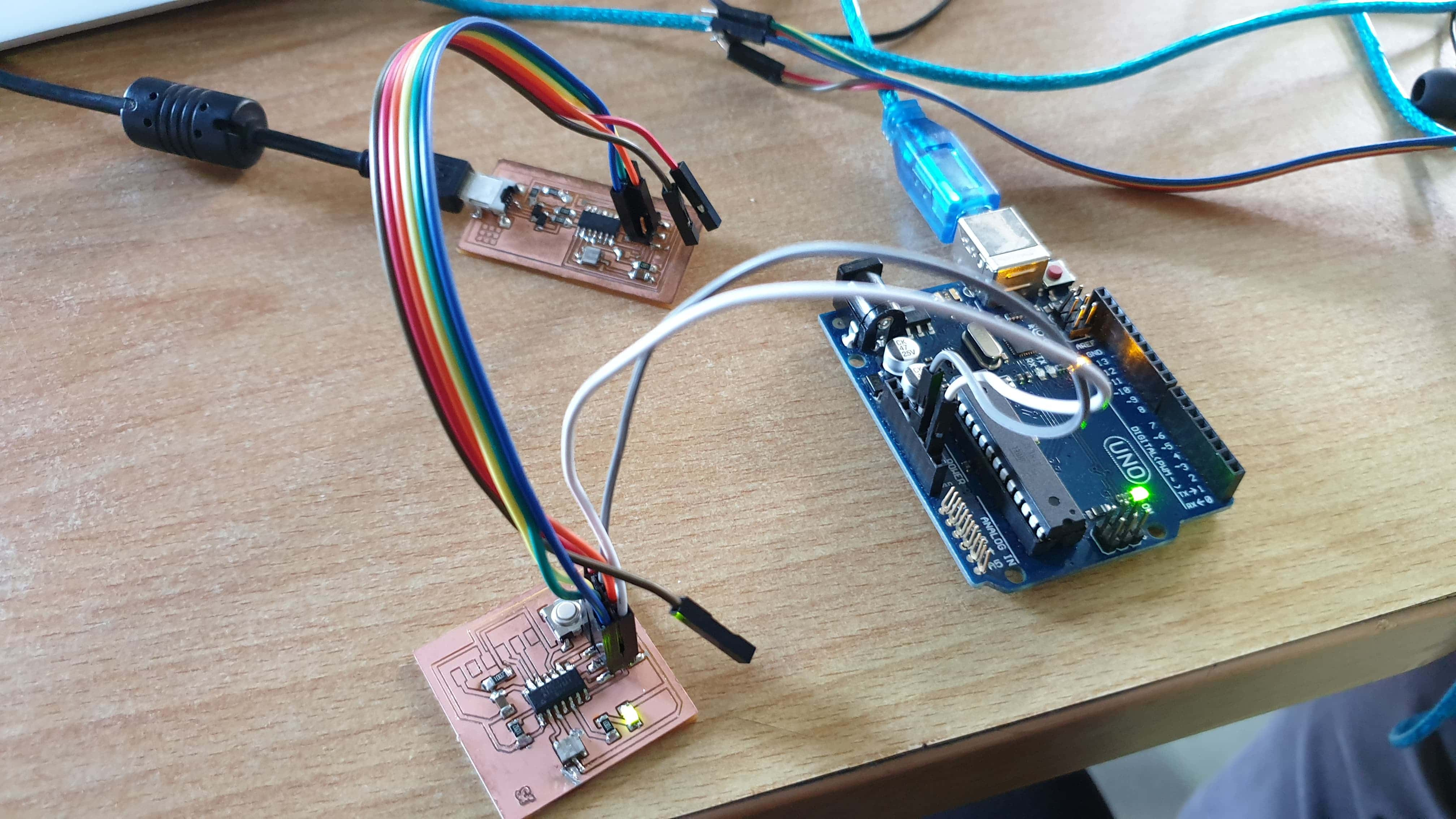
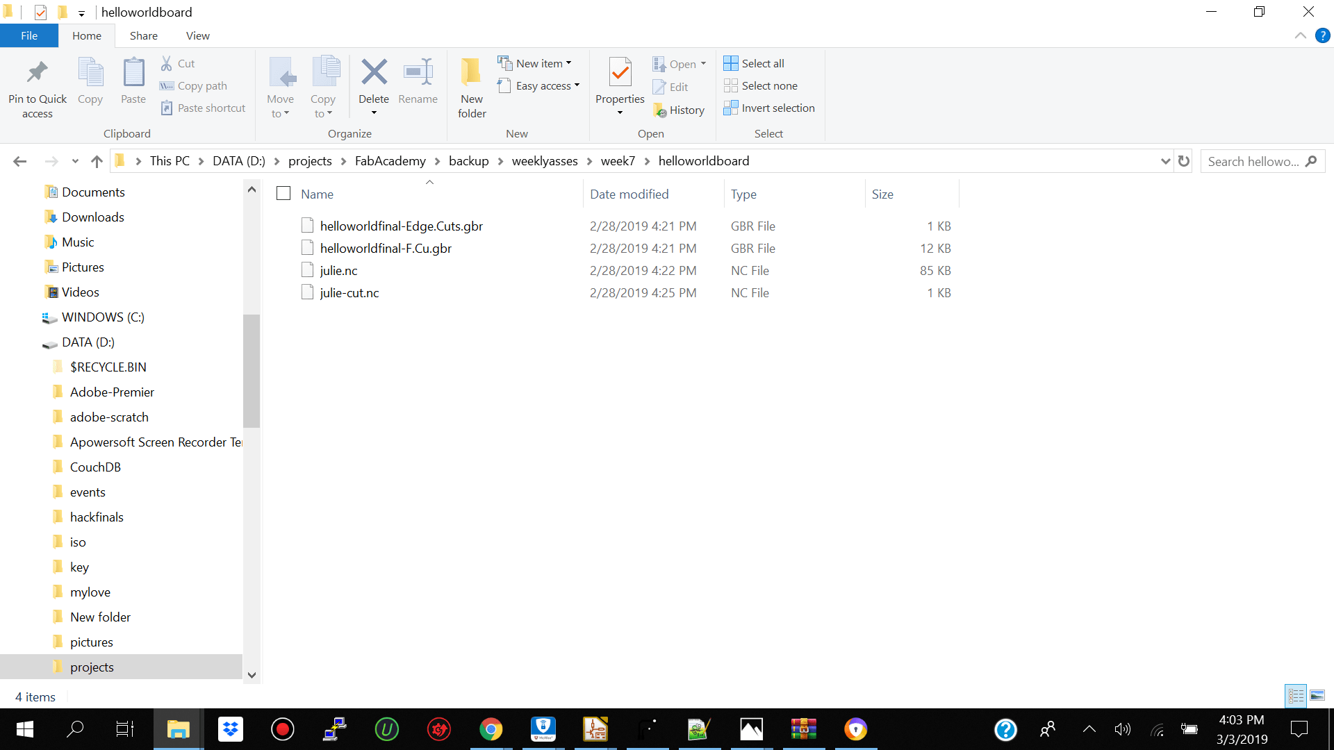
When I was done I went and exported two .nc files.One was the inner cutting of my pcb which I called julie.nc and the other was the outerpart which I called julie-cutout.nc
Lessons
I wasted a lot of time having to change my routes because I placed them too close to each other. When making your route tracks make sure you keep a reasonable amount of space between them so that when it's time to cut your traces out they don't connect.