Assignment
GROUP ASSIGNMENT:
Probe an input device's analog levels and digital signals
INDIVIDUAL ASSIGNMENT:
Measure something: Add a sensor to a microcontroller board
that you have designed and read it
In this week assignment is to conect a Sensor or any input devices
to a microcontroller then Read the values reading by the sensor and
then display the values in PC using a UART communication.
List of available sensors in my lab
- PIR
- Hall effect sensor
- Phototransistor
- Joystic
What I did
- Designed a PCB with a phototransistor using Autodesk Eagle
- Milled using Roland Modela Mdx-20
- Soldered components
- Programed The board using ISP
- Measured analog and digital levels of input device
Input Devices
A component or peripheral device (such as a barcode reader, graphic tablet, keyboard, magnetic-stripe reader, modem, mouse, scanner, or stylus) that feeds data or instruction into a computer for display, processing, storage, or outputting or transmission. Input devices convert the user's actions and analog data (sound, graphics, pictures) into digital electronic signals that can be processed by a computer. Digital data (such as from barcode readers, modems, scanners, etc.) does not require any conversion and is input direct into a computer. It is through input devices that a user exercises control over a computer, its operations, and outputs.
Sensors
In the broadest definition, a sensor is a device, module, or subsystem whose purpose is to
detect events or changes in its environment and send the information to other electronics,
frequently a computer processor. A sensor is always used with other electronics, whether as
simple as a light or as complex as a computer. Learn more from here. We have different type
sensors are available in the market with high quality sensitivity level. But sensors are
comes mostly in two type ANALOG sensor and DIGITAL sensor. The Analog sensors can serve a
percisional reading because it can give us analog output. So a small fluctuations in the sensitiviy
can be read by using analog sensors. But the digital sensor's sensitivity is great, but we could get
the digital reading of the sensor (0 & 1) technically HIGH and LOW values. So in some cases digital
sensors are better to use. But if you need precisional reading its better to use analog sensors. I
will expain more about in the group assignment section.
Source
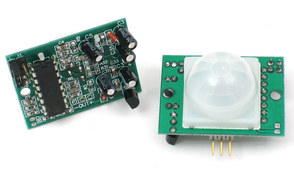
Passive Infrared Sensor (PIR Sensor)
PIR sensors allow you to sense motion, almost always used to detect whether a human has moved in or out of the sensors range. They are small, inexpensive, low-power, easy to use and don't wear out. For that reason they are commonly found in appliances and gadgets used in homes or businesses. They are often referred to as PIR, "Passive Infrared", "Pyroelectric", or "IR motion" sensors.
 Source
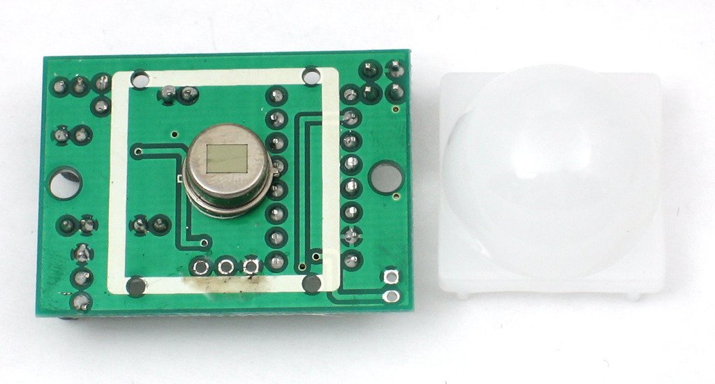
PIRs are basically made of a pyroelectric sensor (which you can see below as the round metal can with a rectangular crystal in the center), which can detect levels of infrared radiation. Everything emits some low level radiation, and the hotter something is, the more radiation is emitted. The sensor in a motion detector is actually split in two halves. The reason for that is that we are looking to detect motion (change) not average IR levels. The two halves are wired up so that they cancel each other out. If one half sees more or less IR radiation than the other, the output will swing high or low.
 Source
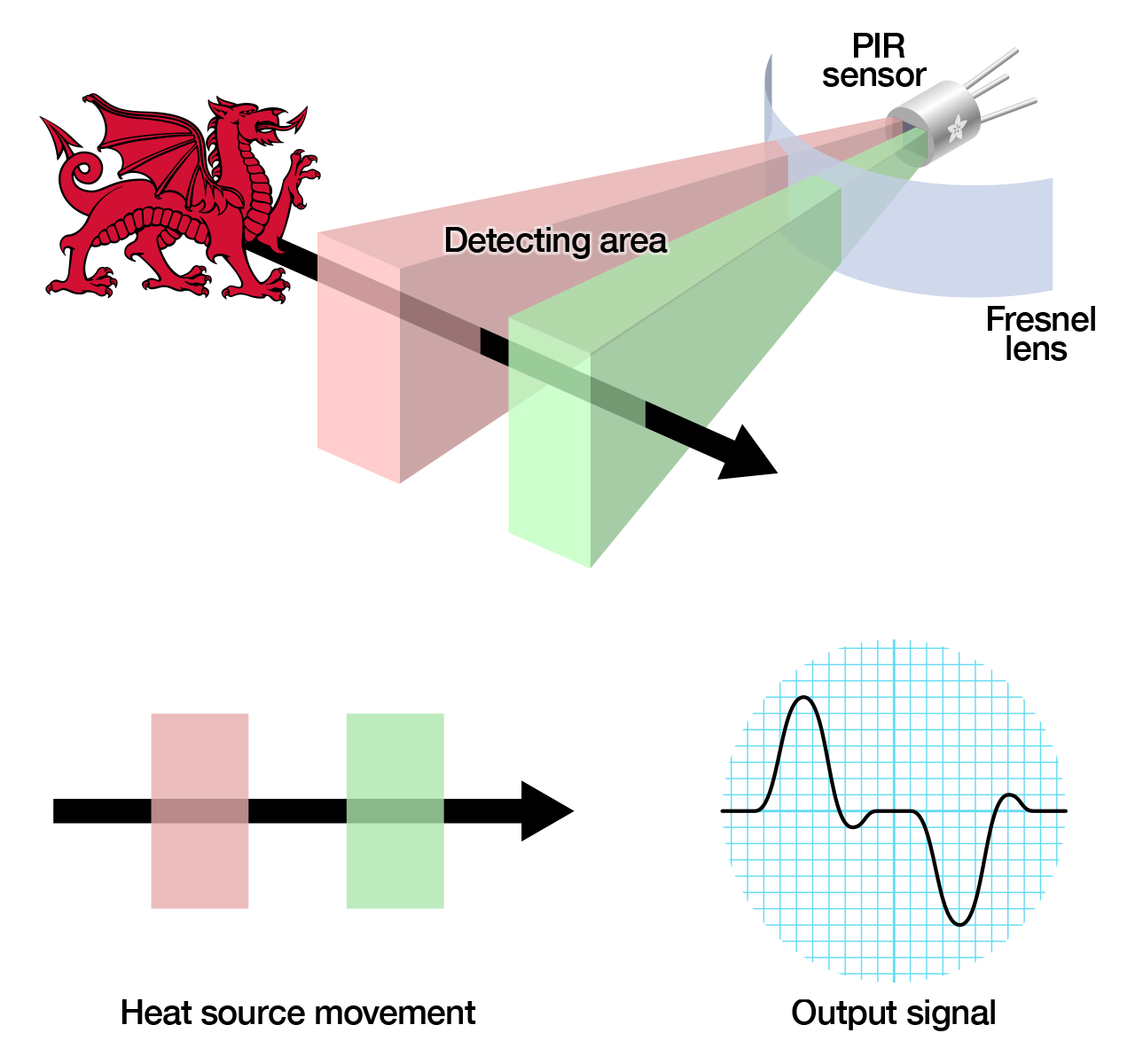
PIR sensors are more complicated than many of the other sensors explained in these tutorials (like photocells, FSRs and tilt switches) because there are multiple variables that affect the sensors input and output. To begin explaining how a basic sensor works, we'll use this rather nice diagram The PIR sensor itself has two slots in it, each slot is made of a special material that is sensitive to IR. The lens used here is not really doing much and so we see that the two slots can 'see' out past some distance (basically the sensitivity of the sensor). When the sensor is idle, both slots detect the same amount of IR, the ambient amount radiated from the room or walls or outdoors. When a warm body like a human or animal passes by, it first intercepts one half of the PIR sensor, which causes a positive differential change between the two halves. When the warm body leaves the sensing area, the reverse happens, whereby the sensor generates a negative differential change. These change pulses are what is detected.
 Source
We have no PIR sensor left, so I decided to use phototransitor
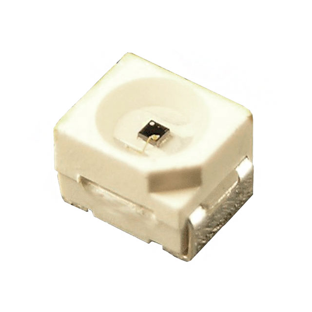
Photo Transistor
 Source
The phototransistor is a device that is able to sense light levels and alter the current flowing
between emitter and collector according to the level of light it receives.The photo transistor
operates because light striking the semiconductor frees electronics / holes and causes current
to flow in the base region.
To learn more about the working of phototransistor refer this
link.
OP580DA (NPN silicon phototdarlington)
Photo darlington devices are normally used in application where light signals are low and more current gain is needed than is possible with phototransistors.
 Source
I'm using OP580DA which is an NPN silicon phototdarlington. The photodarlington photodetector can be used where high levels are gain are needed in a light sensor or detector.
 Source
The photodarlington symbol is a combination of the standard phototransistor symbol and the Darlington transistor symbol.
 Source
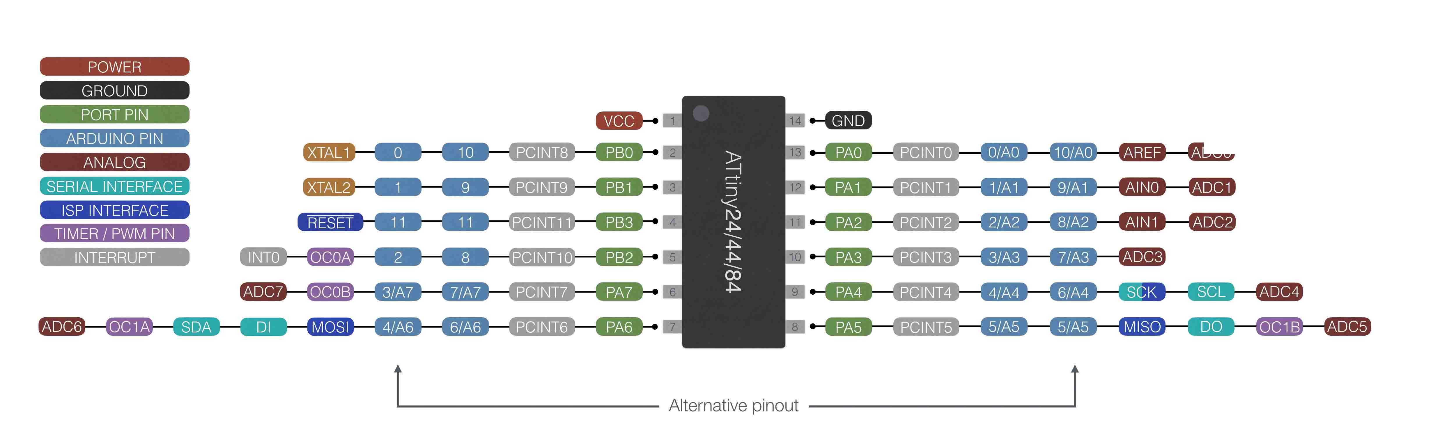
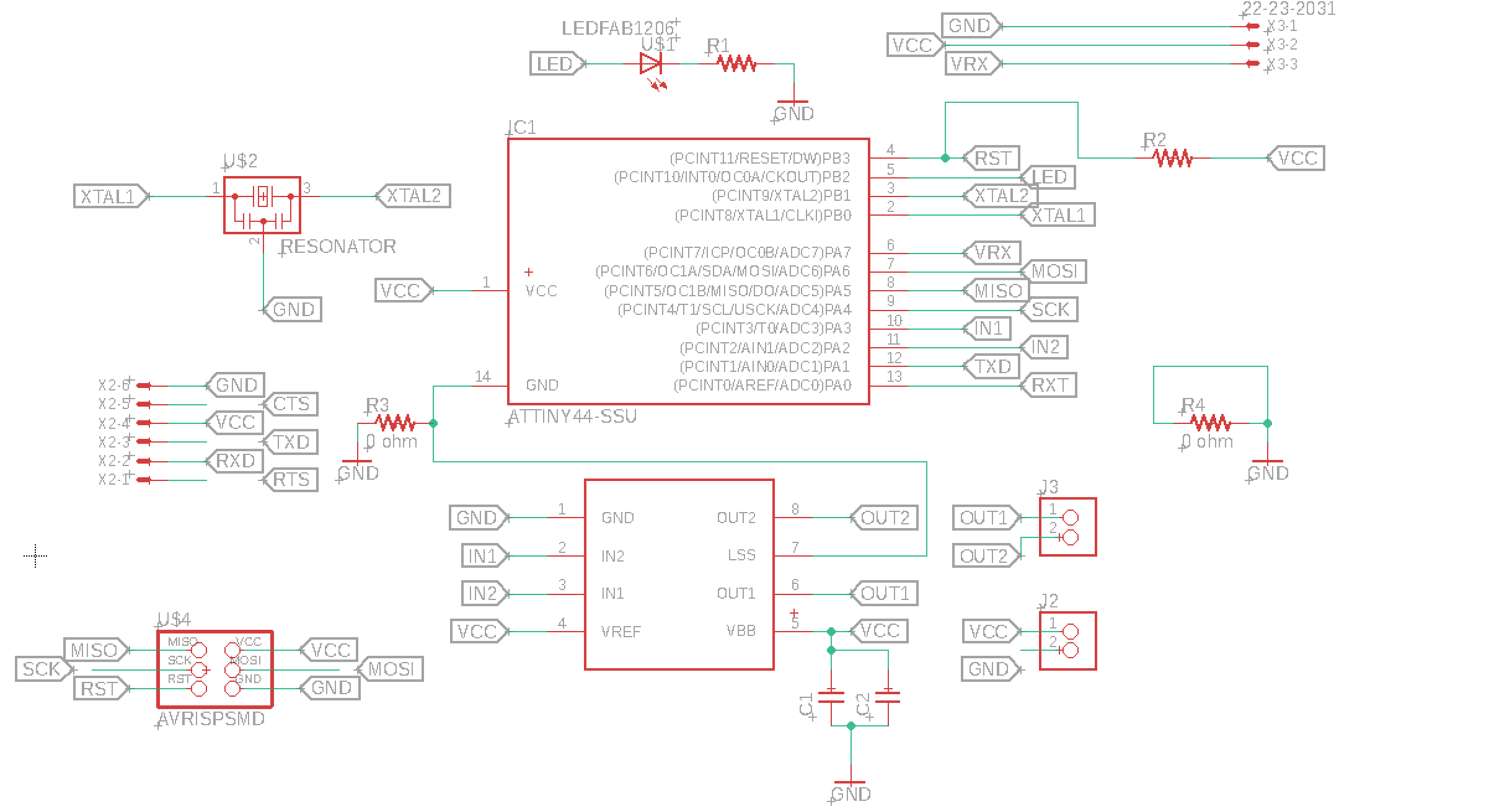
For this purpose I am using ATTINY44 IC. This is the diagram of
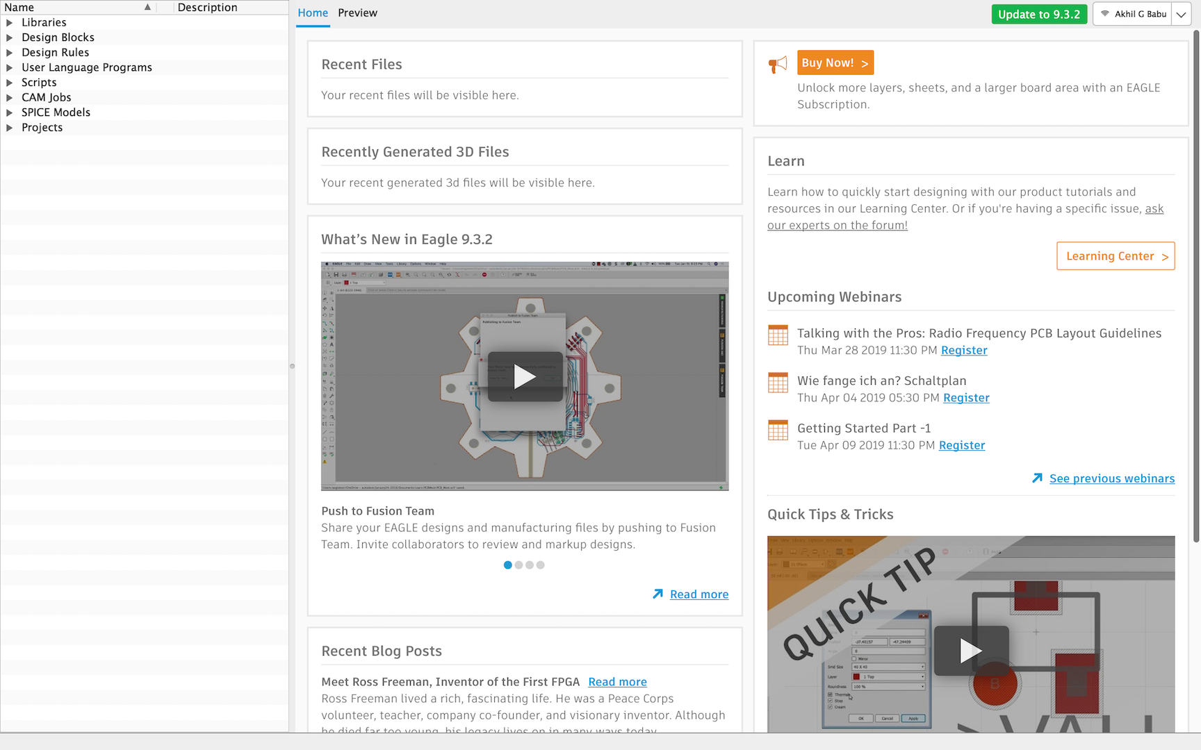
Start designing the circuit board using Autodesk EAGLE. I learned PCB design in Week 7
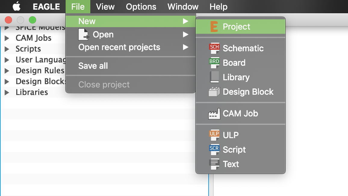
Go to file and create new project
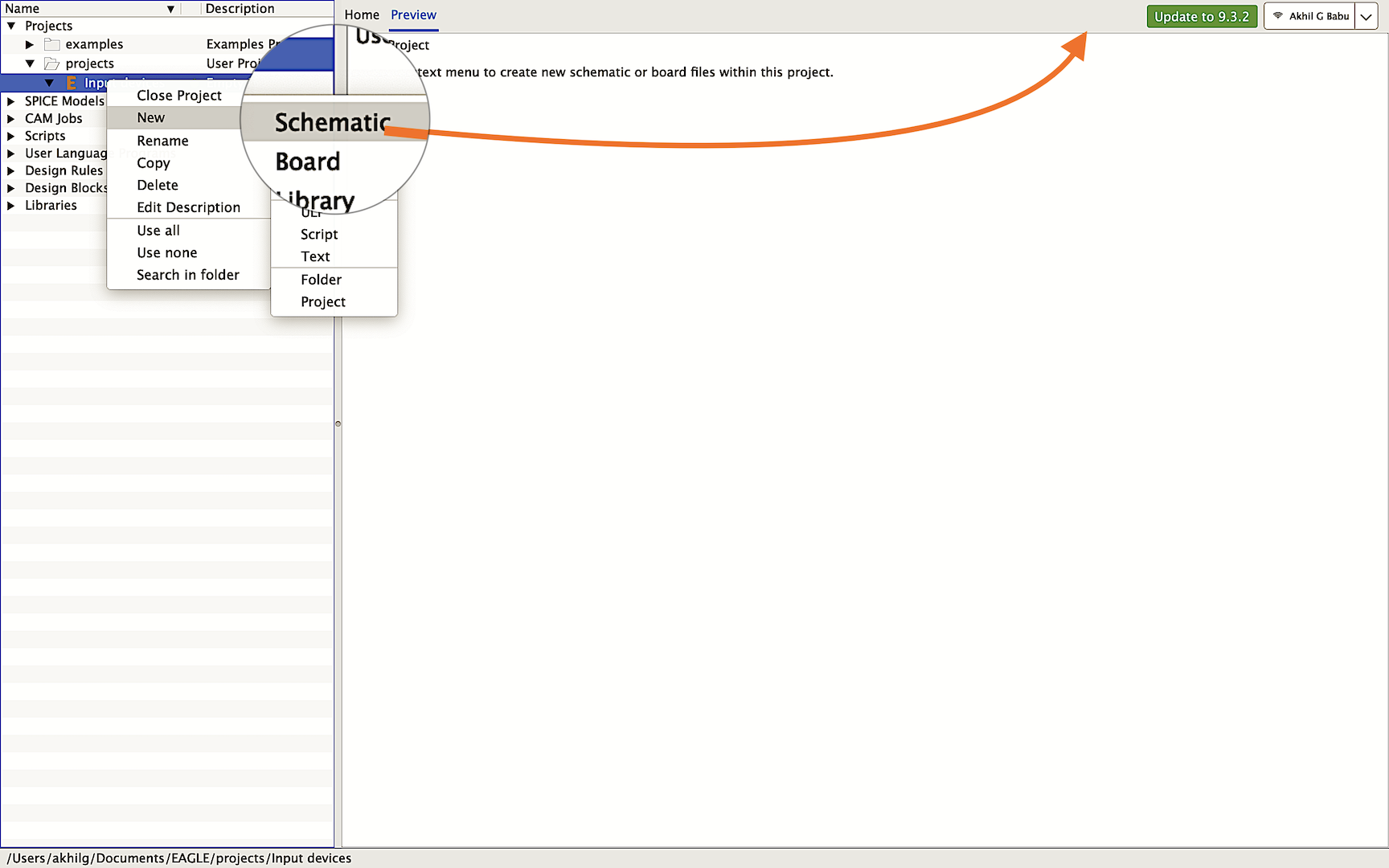
Create new schematics
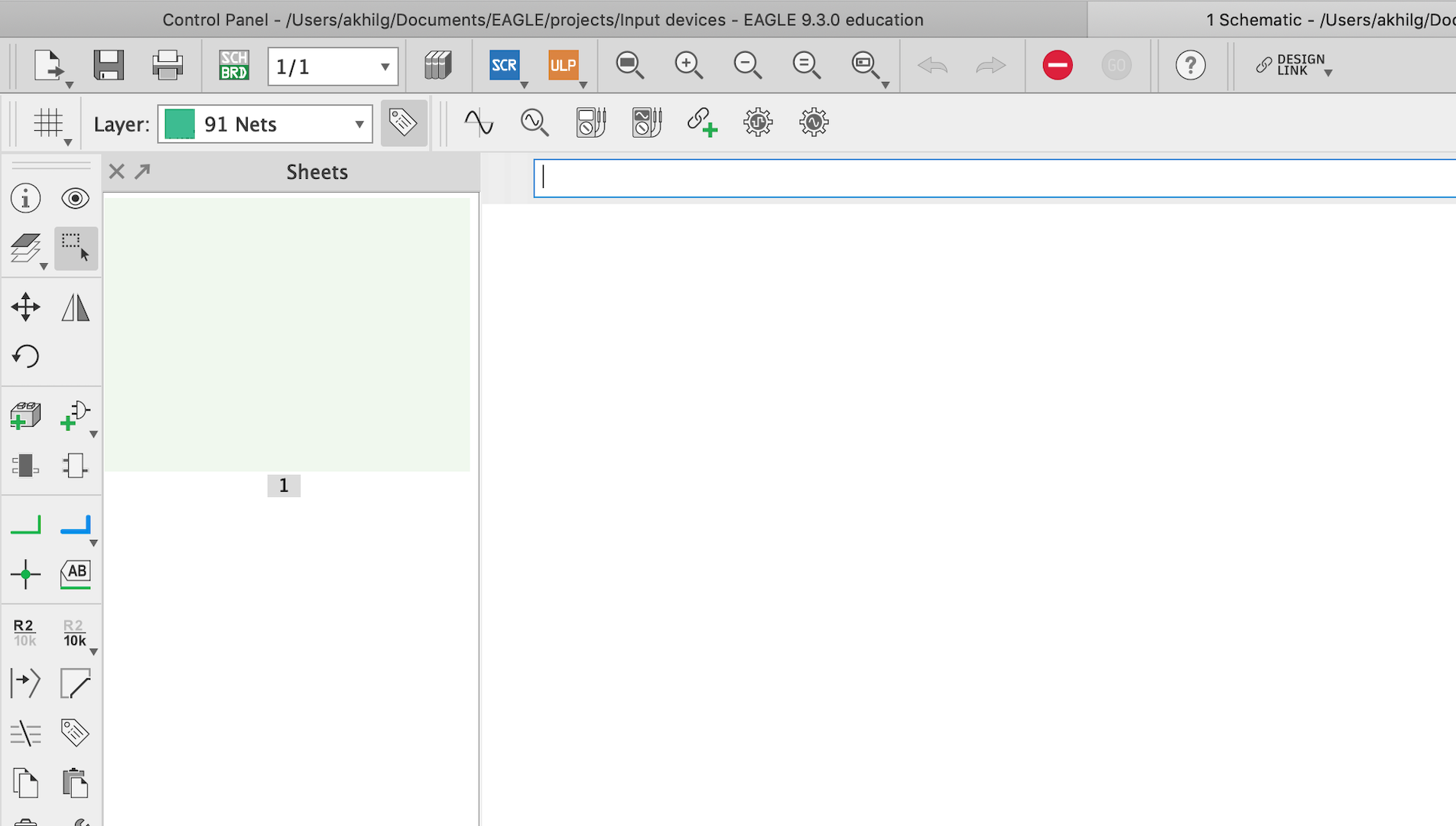
Typeaddto start add components to the schematics
I have not installed the fab library to my ne PC. I will go through the steps to install the library.
FAB library includes the components available in fablab

Download the library from link below to skip some steps
Fab.lbr
Or go to this fab archiveand follow the

Click on raw button to view the library in text format. Copy the text and create a text document in computer then the paste the text and save with the extension ".lbr"
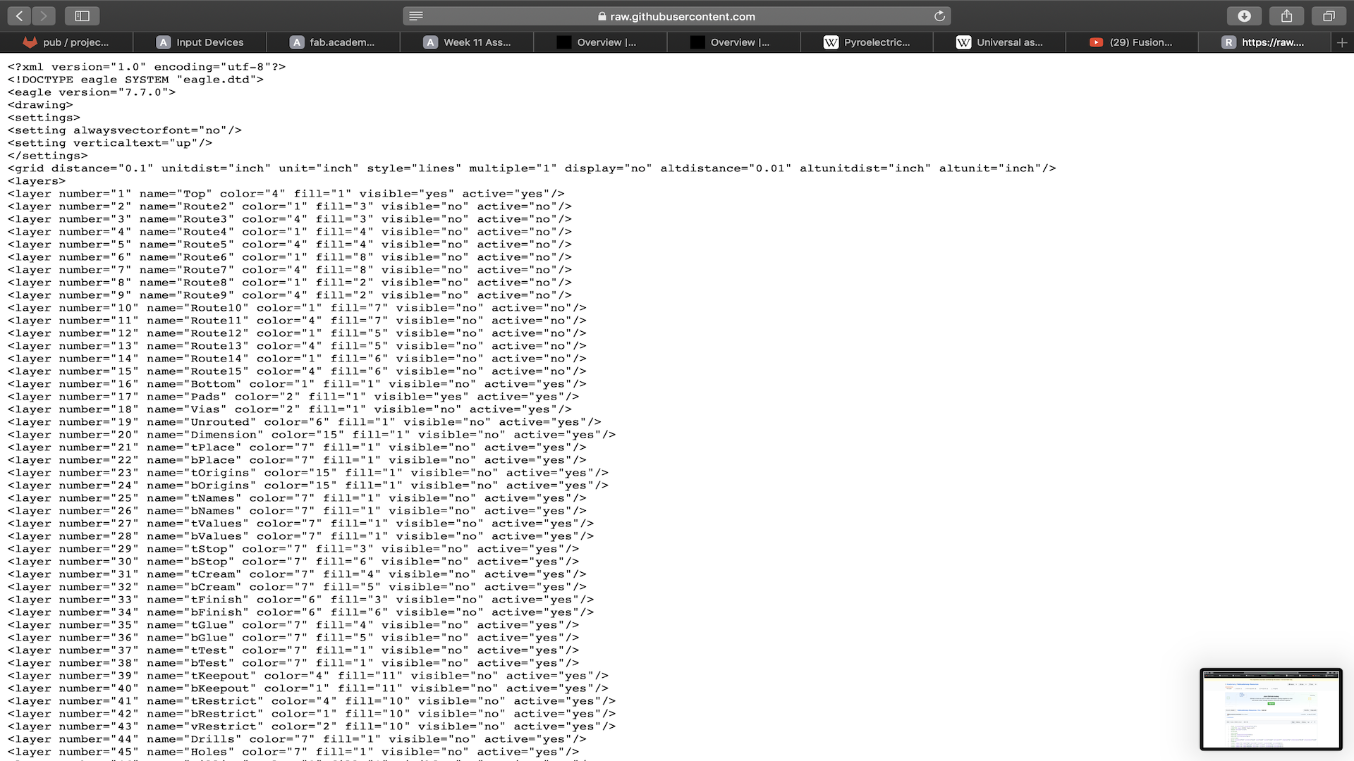 Fab.lbr
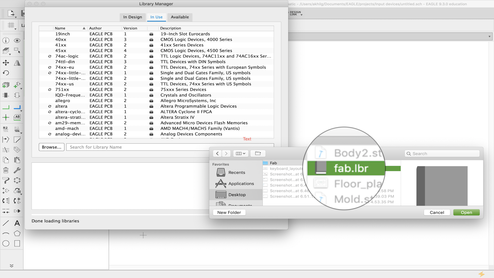
Go to LIBRARY - LIBRARY MANAGER - AVAILABLE - BROWSE
Select the fab library and add
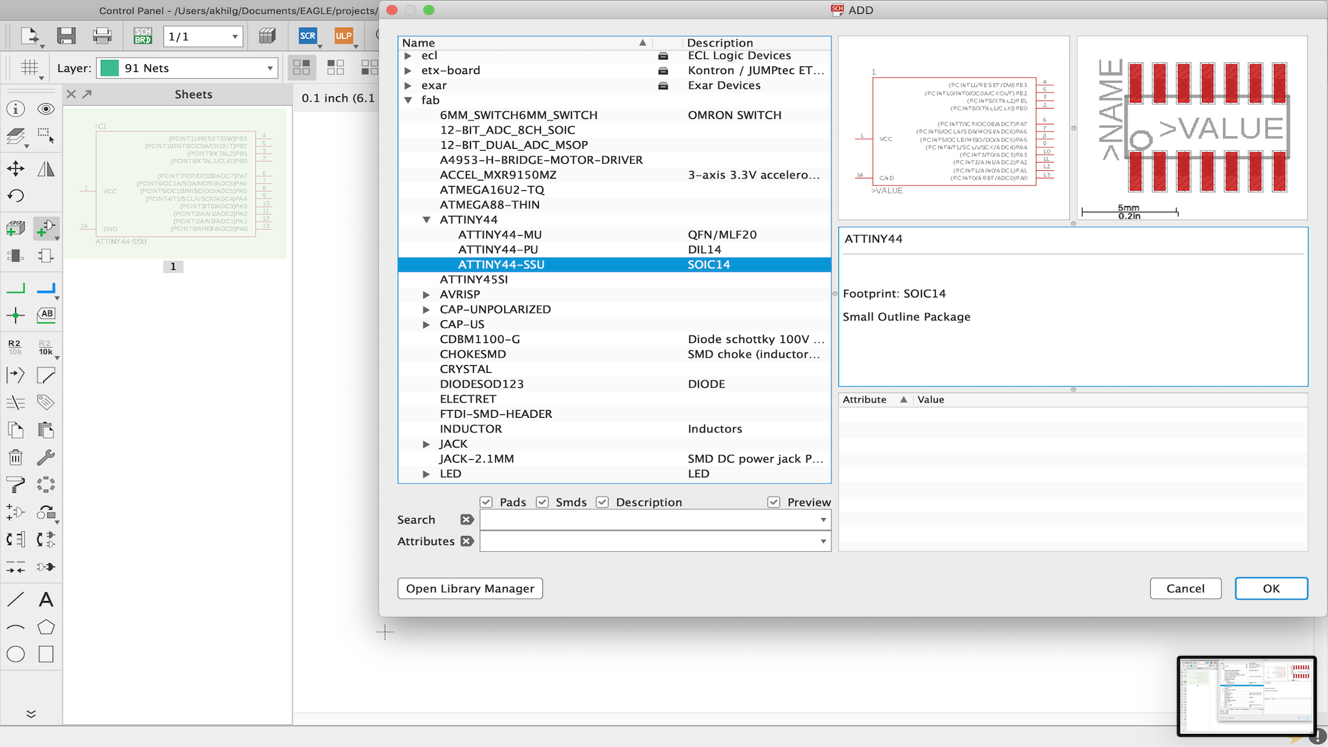
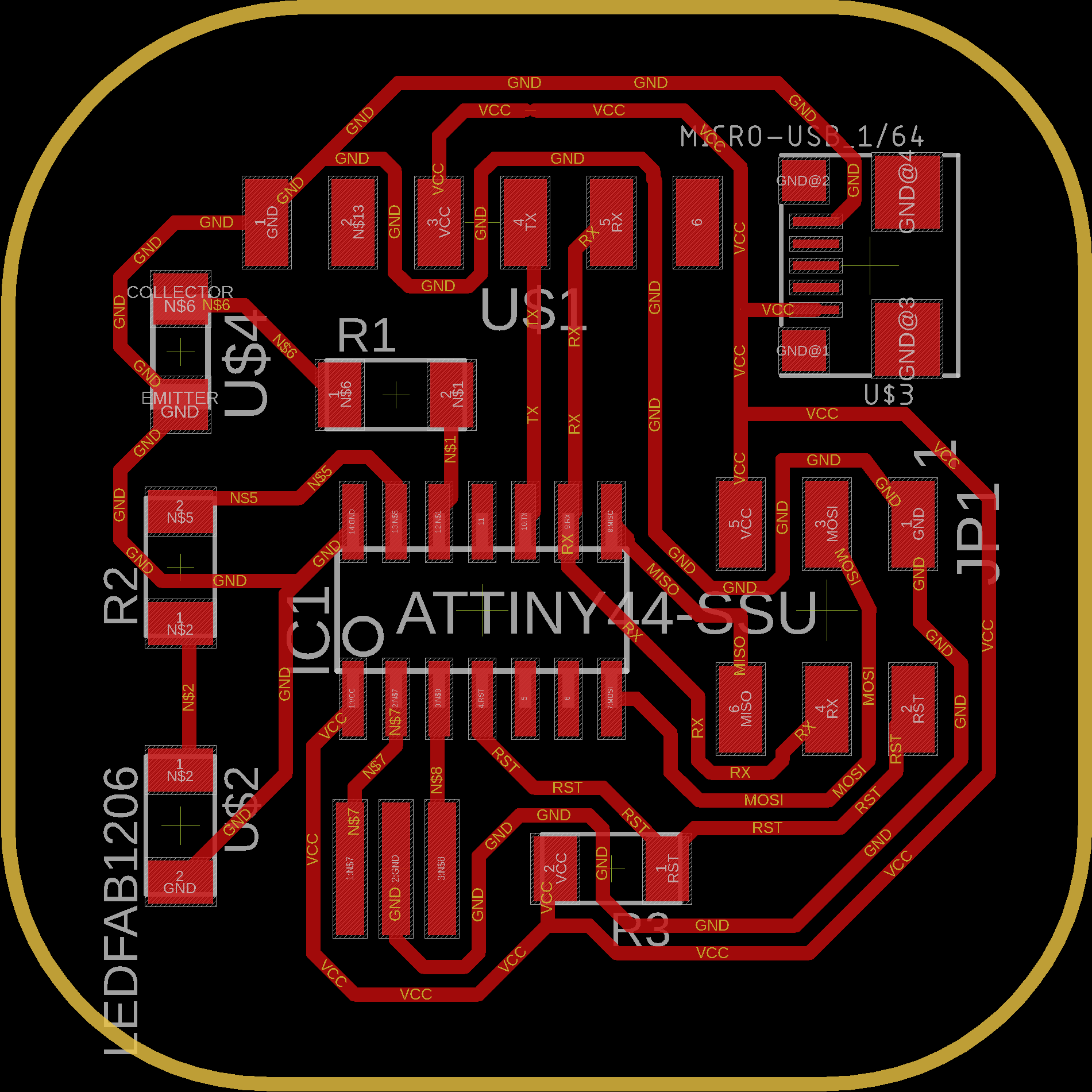
I have used attiny 44 for this pcb
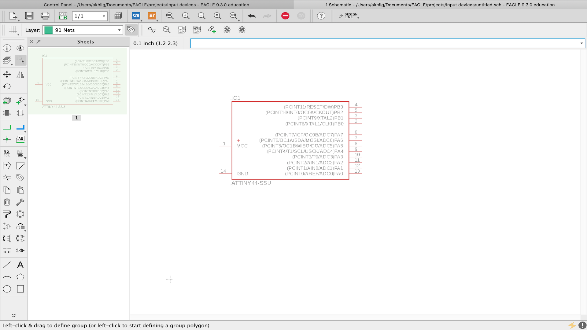
I wanted to experiment with the new IC. I decide to take maximum terminals out of the IC. I added to two ISP header for future use
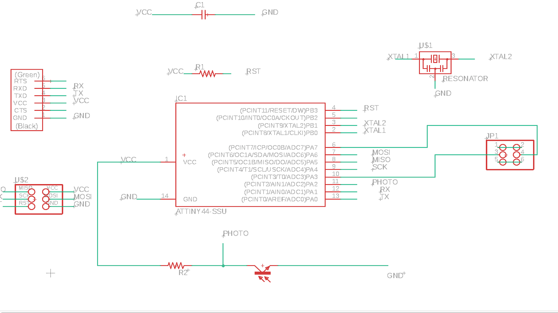
I added FTDI header which will be used for reading and displaying on the the computer
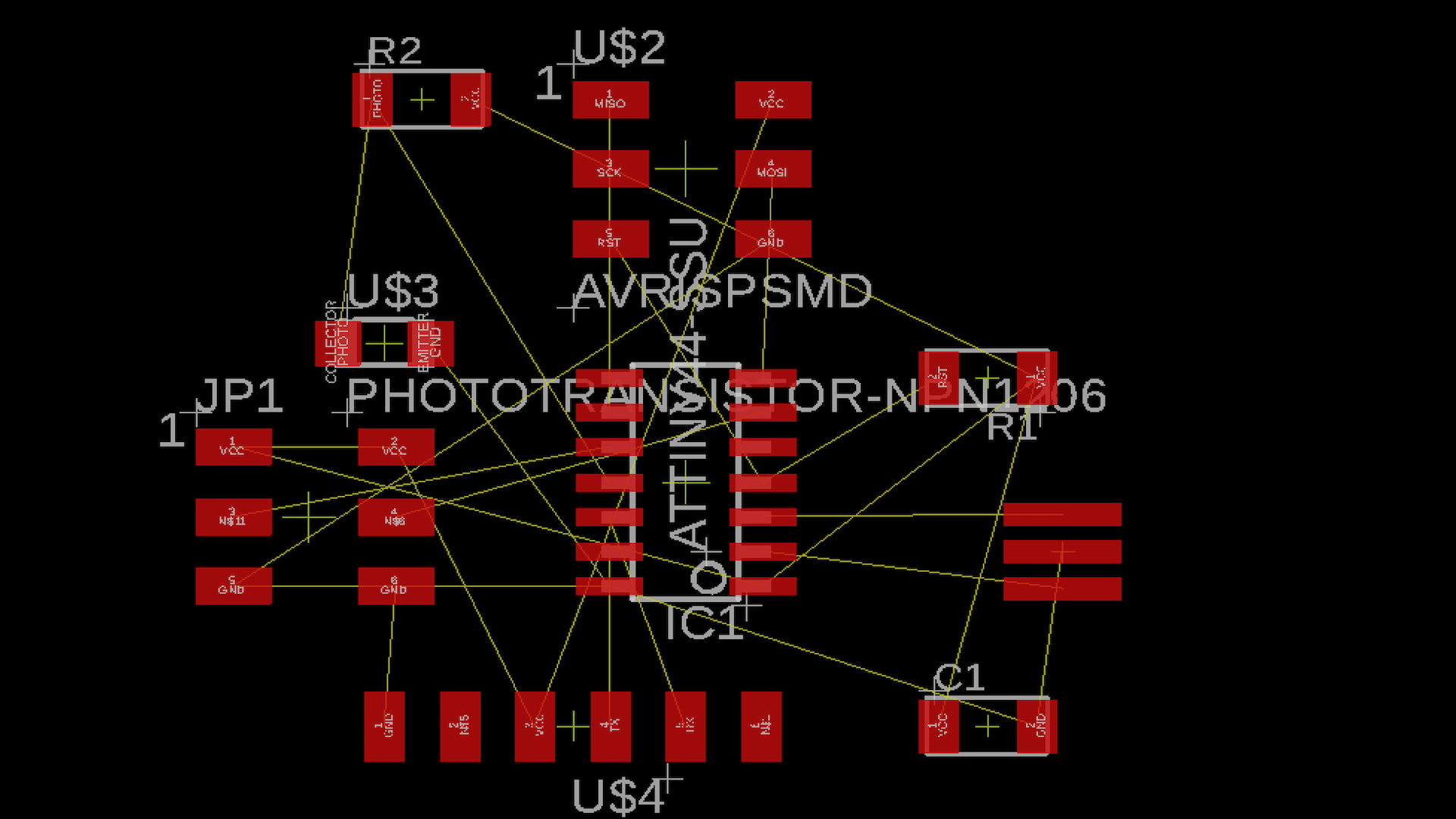
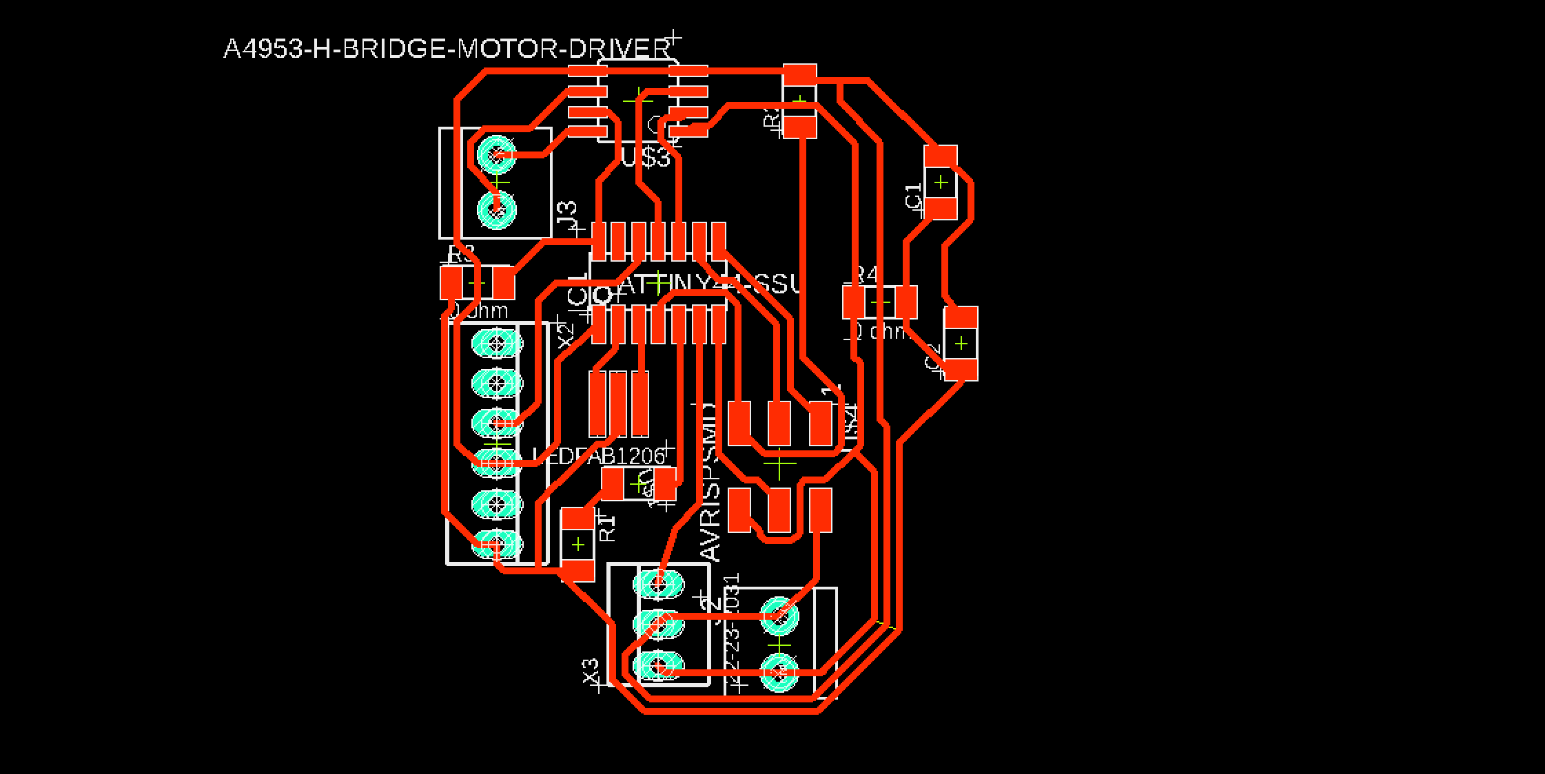
I wanted the circuit to be as compact as possible. This made routing a difficult task. I coud'nt do it completely, had to seek help from my istructor
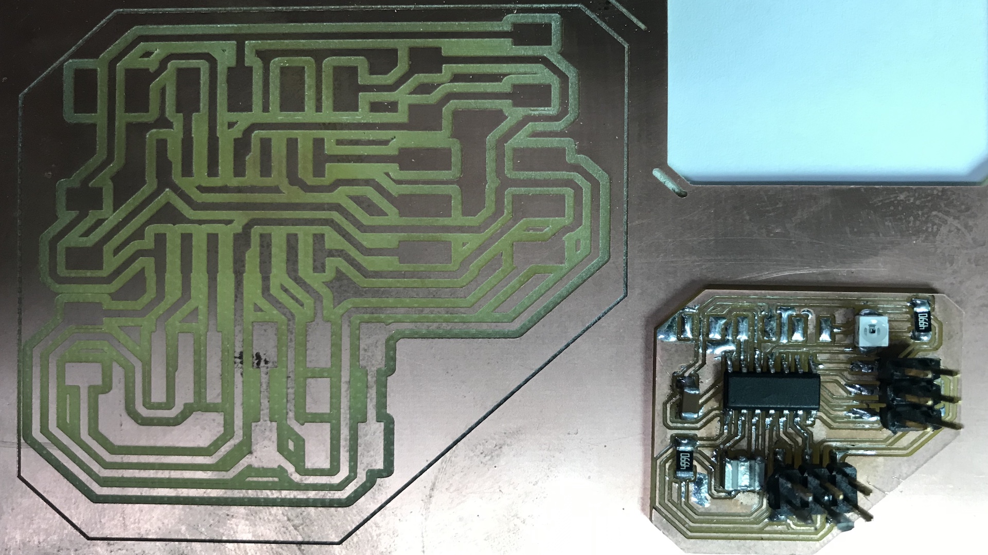
I milled the board and realised that the board is 3 times larger than required size.I recently switched from windows to macbook and coudn't find the reson behind it. I codn't find a solution for this problem, so I copied all the design files and made the milling and png file in Windows PC. It worked well.
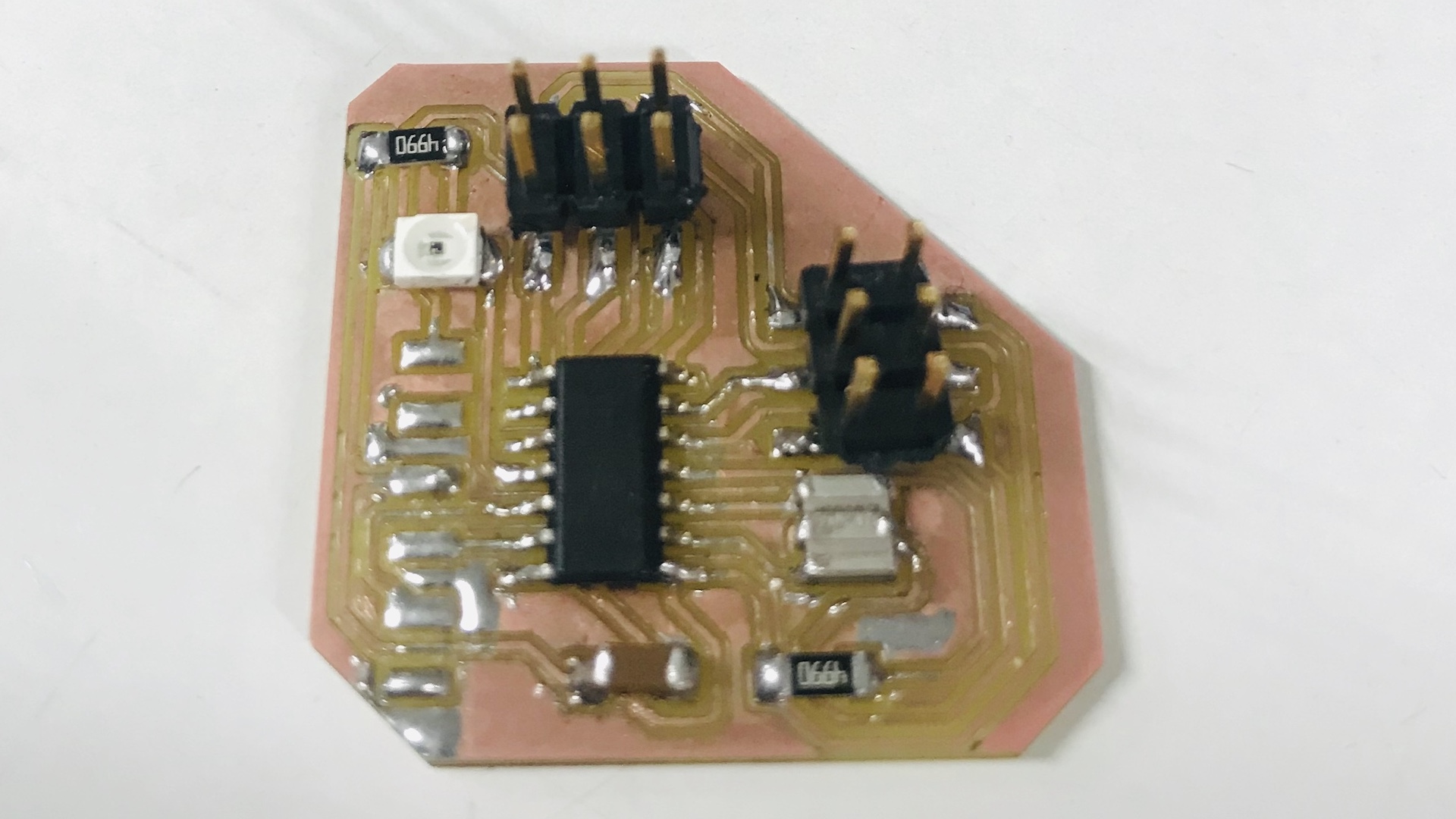
This is the finished circuit board. When I tried to program the board smoke came from the board.
I tried to find the source of the smoke so that I can replace that particular part
First I checked the board using microscope for burned parts or bad solder, coud't find any. Then checked with Multimter for continuity.
Everythig was fine but the board was not working. I seeked help from my instructors, but the problem was never solved.
I think I burned the IC and decided to desiugn a new board.
Second failed attempt
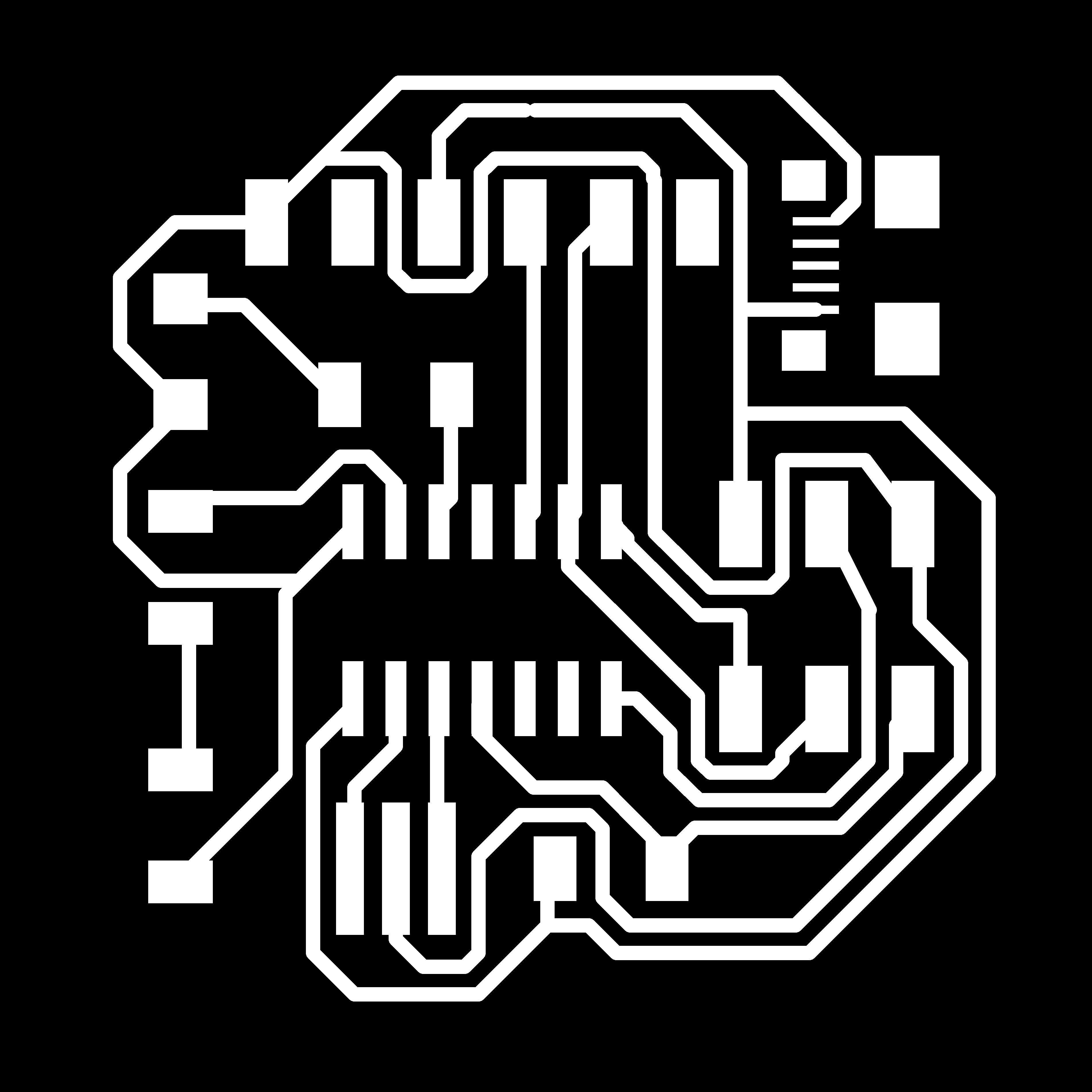
I decided to another circuit, exported Mill and Cut images and Monochrome.

This time I designed board with one ISP header to avoid complications
I was trying to make different shapes for the Circuit board
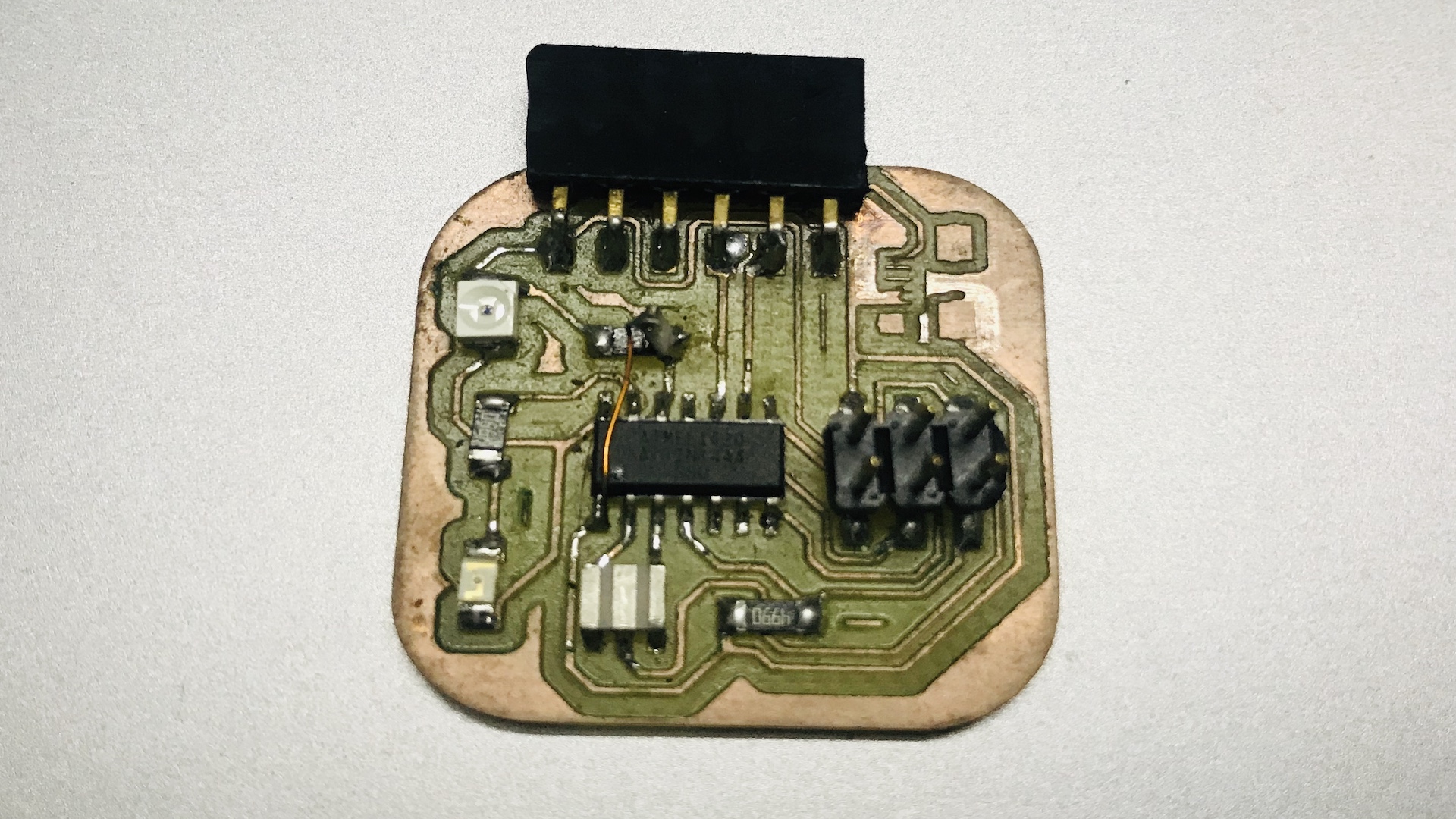
finally made the pcb. This is the finished circuit board. When I tried to program the board, the ISP cannot detect it. This PCB is also not working. I found one issue with the board, and added pull up resister in the the circuit. I added it using a jumper wire. Even after adding that the circuit was not working.
At this point I was frustrated
Third unfinshed attempt
After two failed attemts I was frustrated and wanted to start from with a new project. I though I should make a motor driver with external circuit
This was a compilcated circuit and I had to seek help from my Instructers to finish the circuit. I was too late to finish this board. I didn't get enough time to finish the board.
Since I coudn't complete the assignments of this week, I will try to complete week 11 & week 12 combined
Group Assignment
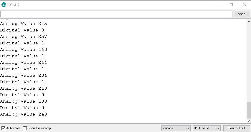
Probe an input device's analog levels and digital signals So I measured the the analog and digital values of the "Hall Effect Sensor". For that I upload the following code to ATtiny 45..
                                    #include <SoftwareSerial.h>
                                    int sensorPin = 1;// hall effect sensor
                                    int digitalValue = 0;// variable to store the value coming from sensor
                                    int analogValue = 0;
                                    SoftwareSerial Serial(3, 4);
                                    void setup()
                                    {
                                         pinMode(sensorPin,INPUT_PULLUP);

                                         Serial.begin(9600); // initialize serial communications at 9600 bps

                                        }
                                        void loop()
                                        {
                                            digitalValue = digitalRead(sensorPin);
                                              analogValue= analogRead(sensorPin);
                                               Serial.print("Digital Value ");
                                             Serial.println(digitalValue); //print the value of sensor in digital
                                             delay(1000);
                                              Serial.print("Analog Value ");
                                             Serial.println(analogValue); //print the value of sensor in analog
                                             delay(1000);
                                            }
Arduino code download
The analog signals are varying when the magnet is bring closer to the sensor. The values are given below
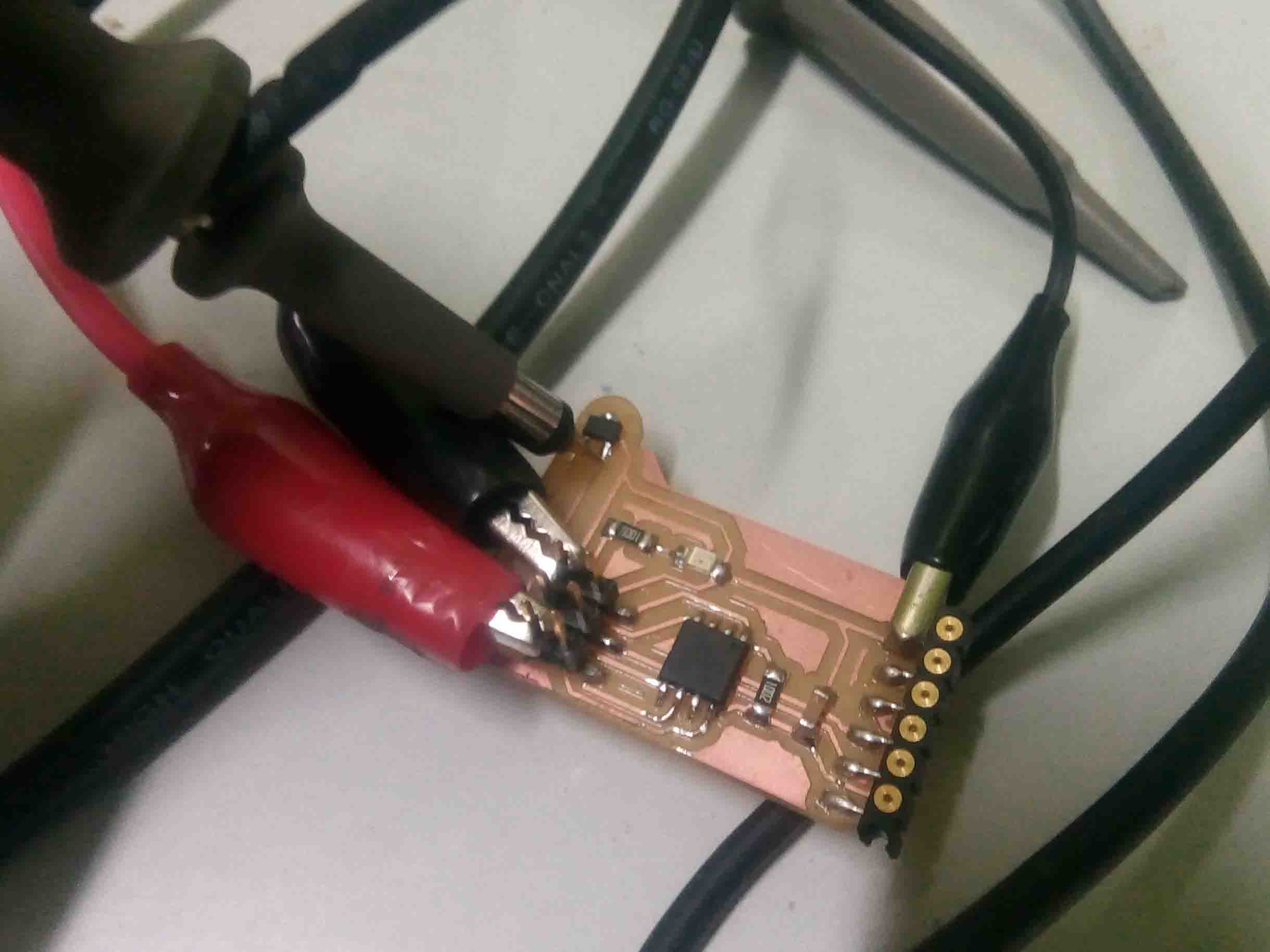
I also confirmed the working using a DSO.
Here is the video