Mechanical Design
- Design a machine that includes mechanism+actuation+automation
- Build the mechanical parts and operate it manually
- Document the group project and your individual contribution
Introduction
We need to do a group assignment in fabacademy. This week and Machine design week are doing a group based assignment. where students can team up and build a machine. The Group assignment splitted to two weeks. In first week we need to plan to build a machine and design the mechanical parts. The next week we need to design the machine and it should be working. We need to split the works between us.
Team Members
Electronics designing
Since I was familier with the designing of many Electronic Systems before. So i decided to go for the Electronics Circuit and Algorithm design parocess . I choose Arduino for coding, And also use Labcenter electronics Proteus 8.0 profesional for Schematics design. I almost took 2 days to make GAME algorithm. And i took 1 day to implement it in arduino. Since everybody contributed to the Design process we could able to design the machine on time.
Grup Work
In electronics part, we 3 Joel George Alex, Jofin Thomas and me works together. I got a bike accident on 2nd april. I hospitalized due to this accident. So i can’t go to LAB in this week. So i take advantage of GIT to collaborate with my partners. To do this, i create a git Repository in gitlab.fabcloud.org.
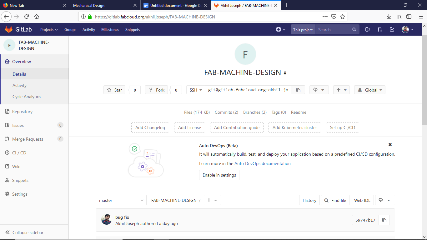
and i add my group members into this repo for collaborated working.
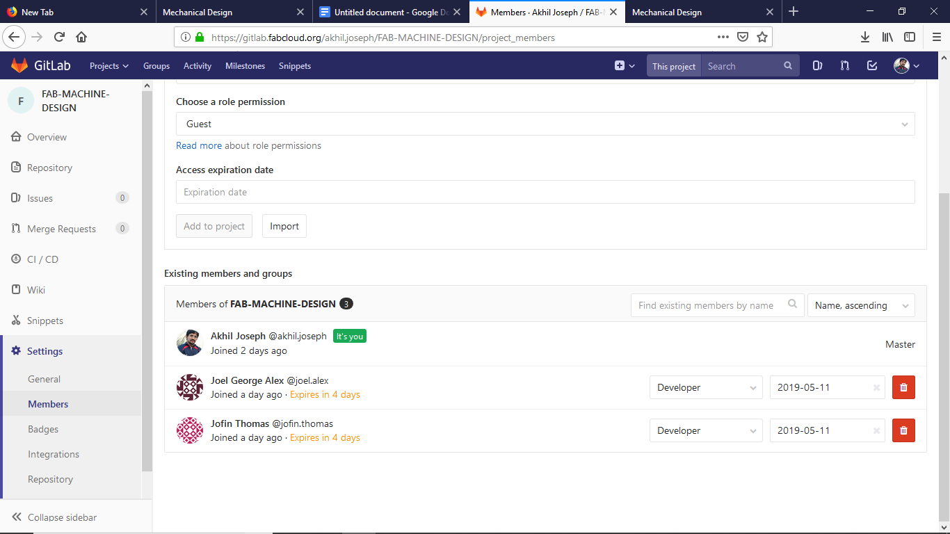
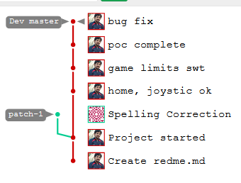
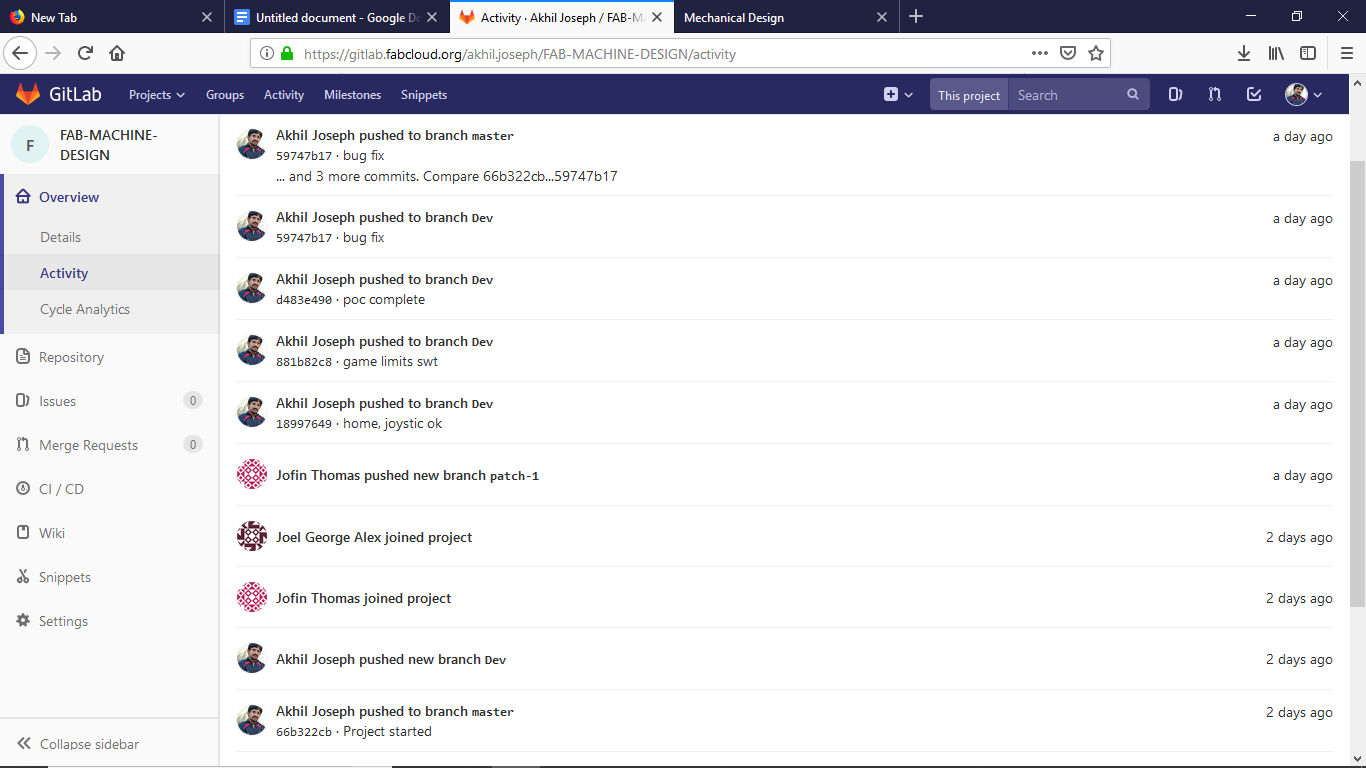
works are in progress. Joffine do the PCB Design and i make the peogram. Joel test each and every components. And i make the Game algorithm and Arduino code. The works are in progress. We all works in different branches. My plan is to Merge each branch to the MASTER branch, after completion.
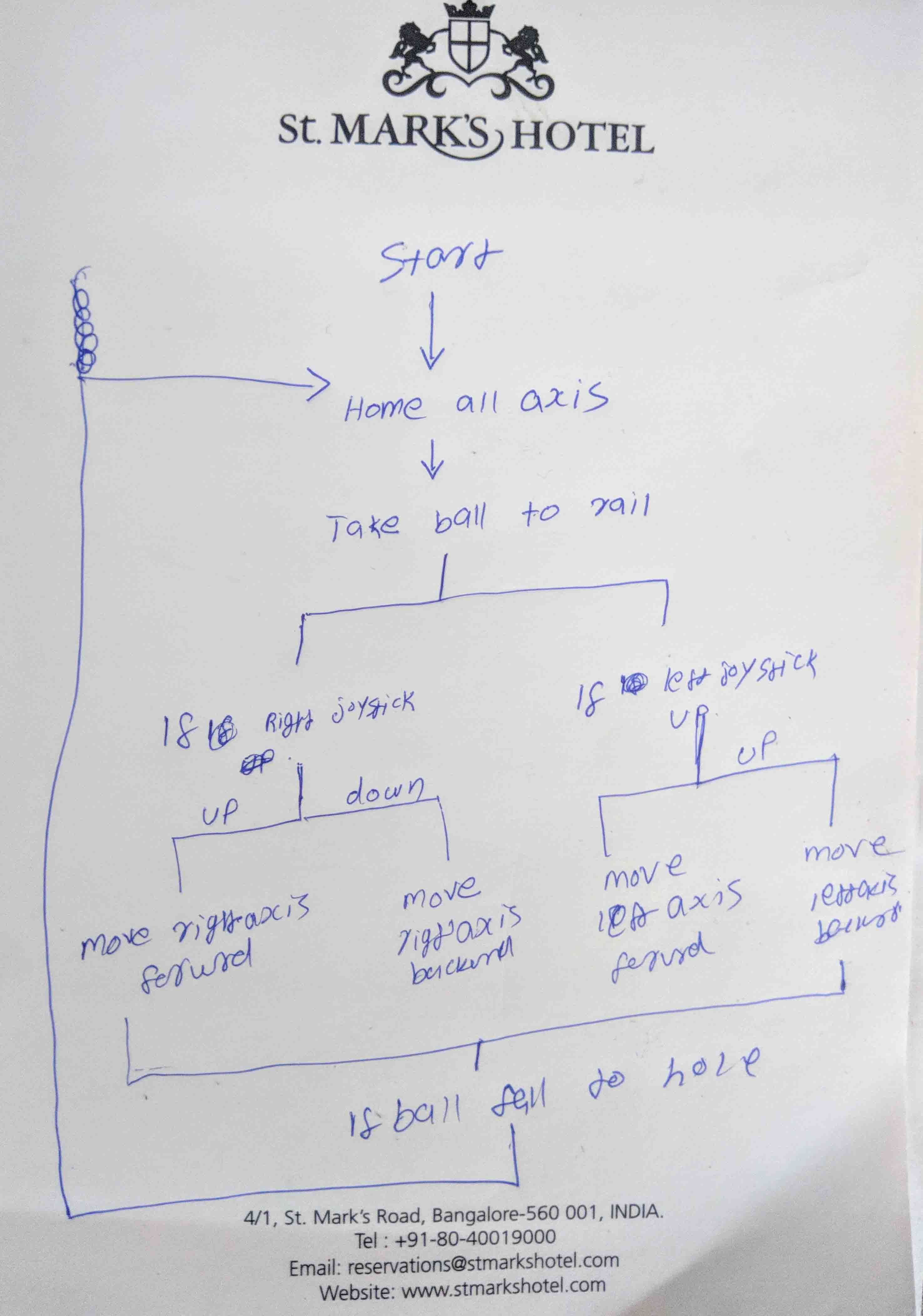
GAME Architrcture Design
This is a game, Thre is a ball on a rail, This rail can move Up/down.
Hardware Architrcture Design

Embedded programing
As an embedded developer the programing is not a complicated task for me. and i also have some previous experience in stepper drivers and controlers. I make one 3D printer as my engineering colage project.
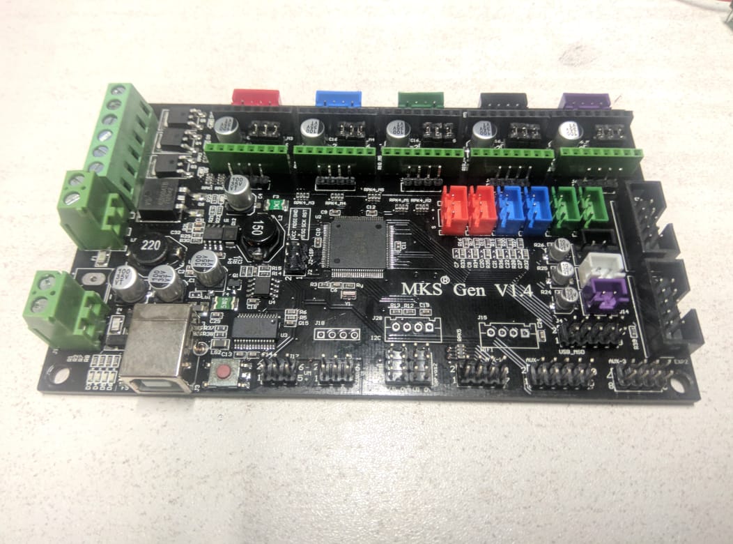
At that time i use MKS GEN 1.4 boards as control board. This time for development i use same board, but just for testing and building. Because it is easy to setup and connect things.
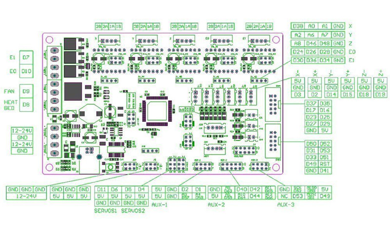
mks gen v1.4 pin Maping
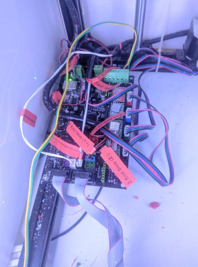
Development setup
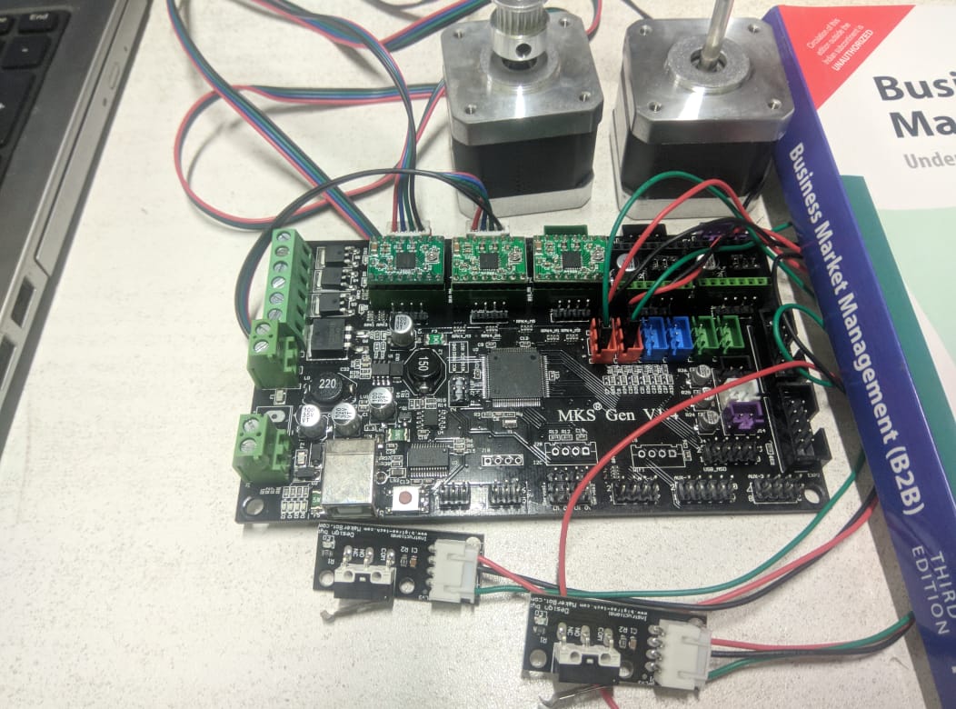
I use this setup to program the board, my plan is to remap the pins after complete the program. so i develope program in that way, which is easy to remap pins.
Pin configration
    //please remape the followingnwith commented pins
    #define ENABLEX 38     // Pin 2 connected to ENABLE pin
    #define step_pinX A0   // Pin 3 connected to Steps pin on EasyDriver
    #define dir_pinX A1    // Pin 4 connected to Direction pin

    #define ENABLEY A2     // Pin 5 connected to ENABLE pin
    #define step_pinY A6   // Pin 6 connected to Steps pin on EasyDriver
    #define dir_pinY A7    // Pin 7 connected to Direction pin

    #define stopperX 3     // Pin 8 connected to limit X-axis
    #define stopperY 2     // Pin 9 connected to limit Y-axis
    #define initButton 14  // Pin 10 connected to GAME start button
    #define gameOver 15    // Pin 11 connected to BALL FALL Detection

    #define X_pin A10      // Pin A0 connected to joystick x axis
    #define Y_pin A9       // Pin A1 connected to joystick Y axis
Hear i use 12GPIOs to develope program
Step function
Stepper driver need step pulses for each steps so i write 2 function to give step pulses for each axis
    void stepX()
    {
      digitalWrite(step_pinX, HIGH);
      delayMicroseconds(400);
      digitalWrite(step_pinX, LOW);
      delayMicroseconds(400);
    }


    void stepY()
    {
      digitalWrite(step_pinY, HIGH);
      delayMicroseconds(400);
      digitalWrite(step_pinY, LOW);
      delayMicroseconds(400);
    }
Homing function
When we initilize the game the controler dont know the current position so the 1st part is goming the axis. i write a function to home both axis. the stepper rotate continously until each axis limit triggered.
    void homeAll()
    {
      flagXR = 1;
      flagYR = 1;
      flagXF = 1;
      flagYF = 1;

      int hflagX = 1, hflagY = 1;
      digitalWrite(dir_pinX, HIGH);
      digitalWrite(dir_pinY, HIGH);
      do
      {
        if ((digitalRead(stopperY)) == 1 && hflagY)
          stepY();
        else
          hflagY = 0;

        if ((digitalRead(stopperX)) == 1 && hflagX)
          stepX();
        else
          hflagX = 0;

      } while (hflagX || hflagY);
    }
Axis limits
Heare we use a single road on a telescopic mechanism, so we need to limit the road in a perticular angle limit. It may be +ve or -ve or nutraal postion. so for this i make a logic to keep each axis within the limit. So this function return a bool value. it may either true or false with respect to the angle limit.
    bool limitS()
    {
      int diff = 0;
      if (stepsX > stepsY)
      {
        diff = stepsX - stepsY;
      }

      else if (stepsX < stepsY)
      {
        diff = stepsY - stepsX;
      }


      if (diff > tiltLimit)
        return 1;
      else
      {
        flagXF = 1;
        flagXR = 1;
        flagYF = 1;
        flagYR = 1;
        return 0;
      }


    }
Main loop
This is the heart of the algorithm. heare we call each functions as we wish.
    void loop() {

      if (analogRead(X_pin) > 400 && analogRead(X_pin) <= 600)
      {
      }

      else if (analogRead(X_pin) >= 0 && analogRead(X_pin) <= 400 && flagXF)
      {
        digitalWrite(dir_pinX, HIGH);  // (HIGH = anti-clockwise / LOW = clockwise)
        stepX();
        stepsX--;
        if (limitS() > 0)
          flagXF = 0;
      }
      else if (analogRead(X_pin) > 600 && analogRead(X_pin) <= 1024 && flagXR)
      {
        digitalWrite(dir_pinX, LOW);
        stepX();
        stepsX++;
        if (limitS() > 0)
          flagXR = 0;
      }

      if (digitalRead(initButton) == LOW)
        homeAll();

      if (analogRead(Y_pin) > 400 && analogRead(Y_pin) <= 600)
      {
        //normal state
      }

      else if (analogRead(Y_pin) >= 0 && analogRead(Y_pin) <= 400 && flagYF)
      {
        digitalWrite(dir_pinY, HIGH);  // (HIGH = anti-clockwise / LOW = clockwise)
        stepY();
        stepsY--;
        if (limitS() > 0)
          flagYF = 0;
      }
Void setup function
This is the function, which excicute when controler initilize. this function is call by controler at booting time. please refer my embedded programing week to learn more about arduino programing.
   void setup() {
     pinMode(dir_pinX, OUTPUT);
     pinMode(step_pinX, OUTPUT);
     pinMode(ENABLEX, OUTPUT);

     pinMode(dir_pinY, OUTPUT);
     pinMode(step_pinY, OUTPUT);
     pinMode(ENABLEY, OUTPUT);

     pinMode(X_pin, INPUT);
     pinMode(Y_pin, INPUT);
     pinMode(stopperX, INPUT);
     pinMode(stopperY, INPUT);
     pinMode(initButton, INPUT);

     Serial.begin(9600);
     Serial.println(analogRead(X_pin));
     Serial.println(analogRead(Y_pin));
     delay(5);  // Wait for EasyDriver wake up
     homeAll();
     }
Final full code
#define maxSteps 1000
#define tiltLimit 100

#define ENABLEX 38     // Pin 2 connected to ENABLE pin
#define step_pinX A0   // Pin 3 connected to Steps pin on EasyDriver
#define dir_pinX A1    // Pin 4 connected to Direction pin

#define ENABLEY A2     // Pin 5 connected to ENABLE pin
#define step_pinY A6   // Pin 6 connected to Steps pin on EasyDriver
#define dir_pinY A7    // Pin 7 connected to Direction pin

#define stopperX 3     // Pin 8 connected to limit X-axis
#define stopperY 2     // Pin 9 connected to limit Y-axis
#define initButton 14  // Pin 10 connected to GAME start button
#define gameOver 15    // Pin 11 connected to BALL FALL Detection

#define X_pin A10      // Pin A0 connected to joystick x axis
#define Y_pin A9       // Pin A1 connected to joystick Y axis

int stepsX, stepsY;


bool flagXF = 1, flagYF = 1, flagXR = 1, flagYR = 1;

void setup() {
  pinMode(dir_pinX, OUTPUT);
  pinMode(step_pinX, OUTPUT);
  pinMode(ENABLEX, OUTPUT);

  pinMode(dir_pinY, OUTPUT);
  pinMode(step_pinY, OUTPUT);
  pinMode(ENABLEY, OUTPUT);

  pinMode(X_pin, INPUT);
  pinMode(Y_pin, INPUT);
  pinMode(stopperX, INPUT);
  pinMode(stopperY, INPUT);
  pinMode(initButton, INPUT);

  Serial.begin(9600);
  Serial.println(analogRead(X_pin));
  Serial.println(analogRead(Y_pin));

  delay(5);  // Wait for EasyDriver wake up
  homeAll();
}

void loop() {

  if (analogRead(X_pin) > 400 && analogRead(X_pin) <= 600)
  {
  }

  else if (analogRead(X_pin) >= 0 && analogRead(X_pin) <= 400 && flagXF)
  {
    digitalWrite(dir_pinX, HIGH);  // (HIGH = anti-clockwise / LOW = clockwise)
    stepX();
    stepsX--;
    if (limitS() > 0)
      flagXF = 0;
  }
  else if (analogRead(X_pin) > 600 && analogRead(X_pin) <= 1024 && flagXR)
  {
    digitalWrite(dir_pinX, LOW);
    stepX();
    stepsX++;
    if (limitS() > 0)
      flagXR = 0;
  }

  if (digitalRead(initButton) == LOW)
    homeAll();

  if (analogRead(Y_pin) > 400 && analogRead(Y_pin) <= 600)
  {
    //normal state
  }

  else if (analogRead(Y_pin) >= 0 && analogRead(Y_pin) <= 400 && flagYF)
  {
    digitalWrite(dir_pinY, HIGH);  // (HIGH = anti-clockwise / LOW = clockwise)
    stepY();
    stepsY--;
    if (limitS() > 0)
      flagYF = 0;
  }

  else if (analogRead(Y_pin) > 600 && analogRead(Y_pin) <= 1024 && flagYR)
  {
    digitalWrite(dir_pinY, LOW);
    stepY();
    stepsY++;
    if (limitS() > 0)
      flagYR = 0;
  }

}

void stepX()
{
  digitalWrite(step_pinX, HIGH);
  delayMicroseconds(400);
  digitalWrite(step_pinX, LOW);
  delayMicroseconds(400);
}


void stepY()
{
  digitalWrite(step_pinY, HIGH);
  delayMicroseconds(400);
  digitalWrite(step_pinY, LOW);
  delayMicroseconds(400);
}

void homeAll()
{
  flagXR = 1;
  flagYR = 1;
  flagXF = 1;
  flagYF = 1;

  int hflagX = 1, hflagY = 1;
  digitalWrite(dir_pinX, HIGH);
  digitalWrite(dir_pinY, HIGH);
  do
  {
    if ((digitalRead(stopperY)) == 1 && hflagY)
      stepY();
    else
      hflagY = 0;

    if ((digitalRead(stopperX)) == 1 && hflagX)
      stepX();
    else
      hflagX = 0;

  } while (hflagX || hflagY);
}

bool limitS()
{
  int diff = 0;
  if (stepsX > stepsY)
  {
    diff = stepsX - stepsY;
  }

  else if (stepsX < stepsY)
  {
    diff = stepsY - stepsX;
  }


  if (diff > tiltLimit)
    return 1;
  else
  {
    flagXF = 1;
    flagXR = 1;
    flagYF = 1;
    flagYR = 1;
    return 0;
  }

}
My work log