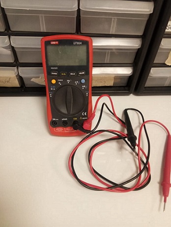
A Multimeter is basically a Paramter measuring tool, which can measure a wide range of parameters, Principally : Voltage (AC/DC), Resistance, Capacitance, Conductivity etc.
Its the most common diagnostic tool technicians have, through multimeter debugging comes handy.
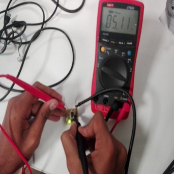
We used Multimeter to check the continuity of the tracks and make sure everything is connected according to the Board Layout
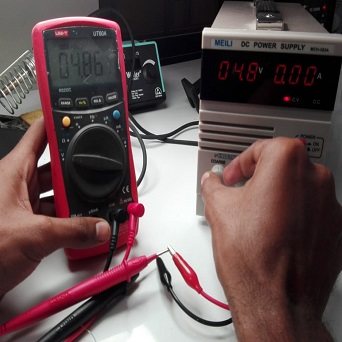
Measuring voltage using Multimeter
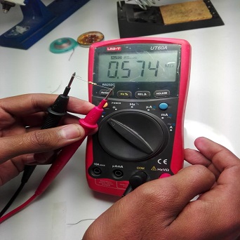
Measuing Resistor Value Using Multimeter
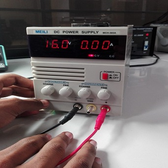
A power supply is an electrical device that supplies electric power to an electrical load. The primary function of a power supply is to convert electric current from a source to the correct voltage, current, and frequency to power the load , As a result, power supplies are sometimes referred to as electric power converters.Wikipedia
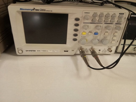
The difference between an oscilloscope and a digital multimeter (DMM) is simply stated as "pictures vs. numbers.
" A DMM is a tool for making precise measurements of discrete signals, enabling readings of up to eight digits of resolution for the voltage, current or frequency of a signal.
On the other hand, a DMM cannot visually depict waveforms to reveal signal strength,. wave shape, or the instantaneous value of the signal. Nor is a multimeter equipped
to reveal a transient or a harmonic signal that could compromise the operation of a system.
An oscilloscope adds a wealth of information to the numeric readings of a DMM. While displaying the numerical values of a wave instantaneously, it also reveals the shape of the wave, including its amplitude (voltage) and frequency.
With such visual information, a transient signal that may pose a threat to a system can be displayed, measured and isolated. An oscilloscope will also graphically show distortion and noise that may be present in the signal.
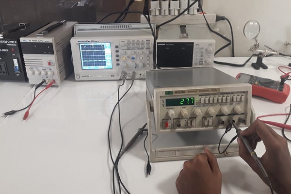
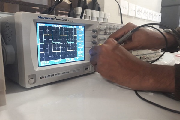
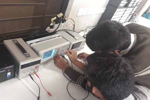
Here are the some images while interacting with oscilloscope in our lab
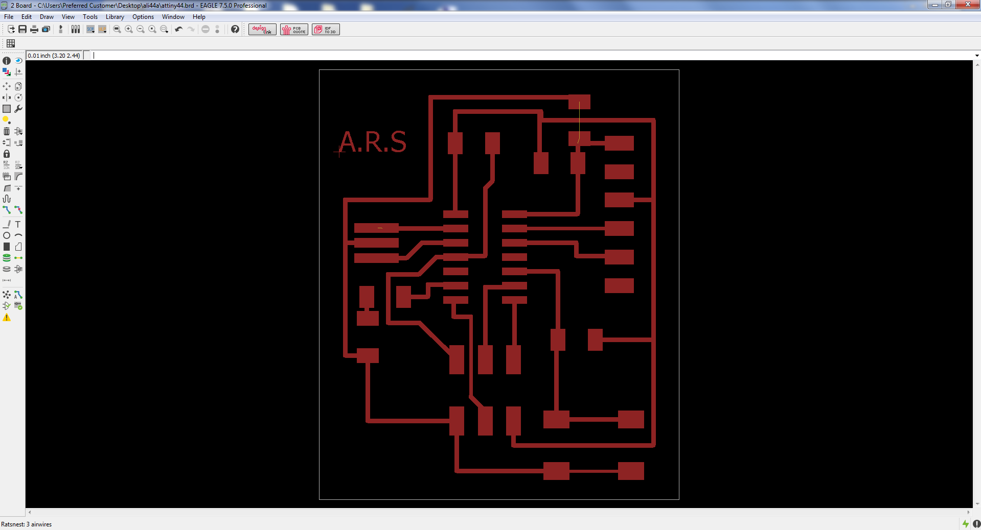
For redrawing echo hello board I used Eagle Software. I used this software first time , before that i have not used this. I installed this from here
I followed the following steps:
1. Open Eagle and login if your using first time.
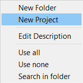
2. Make a new project
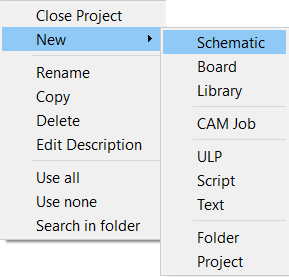
3. Choose Schematic
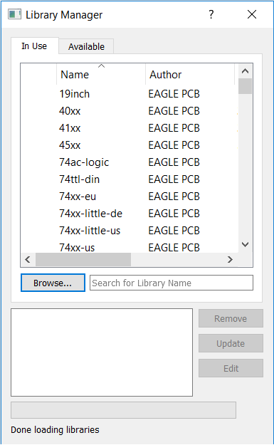
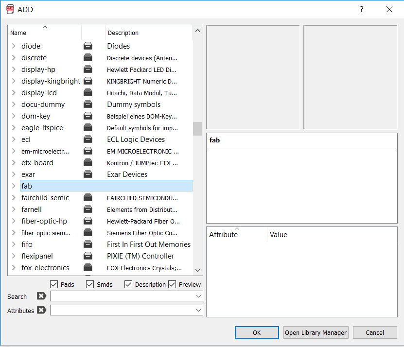
4. Select Option USE to choose library.
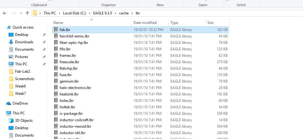
I started by importing FAB LIBRARY to Eagle. You can download the library fromhereInstruction to install the library can be found here.
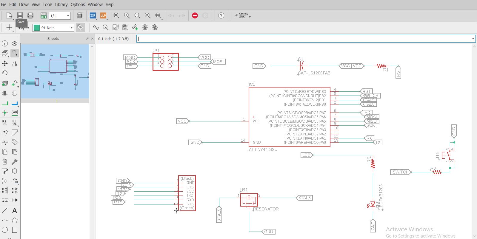
A) Resistors
B) Capicitors - 1 uf
C) IC Attiny 44
D) Connectors 2x3 and 6x1p>
E) Resonator
F) LED
G) Push Button
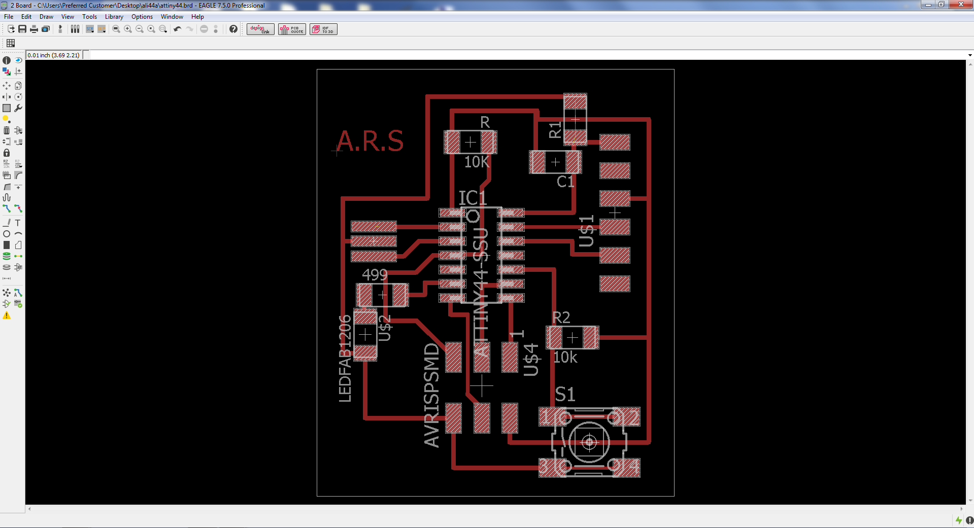
Now to convert this schematic to Board layout we need to click on this Icon over the tool bar SCH BRD
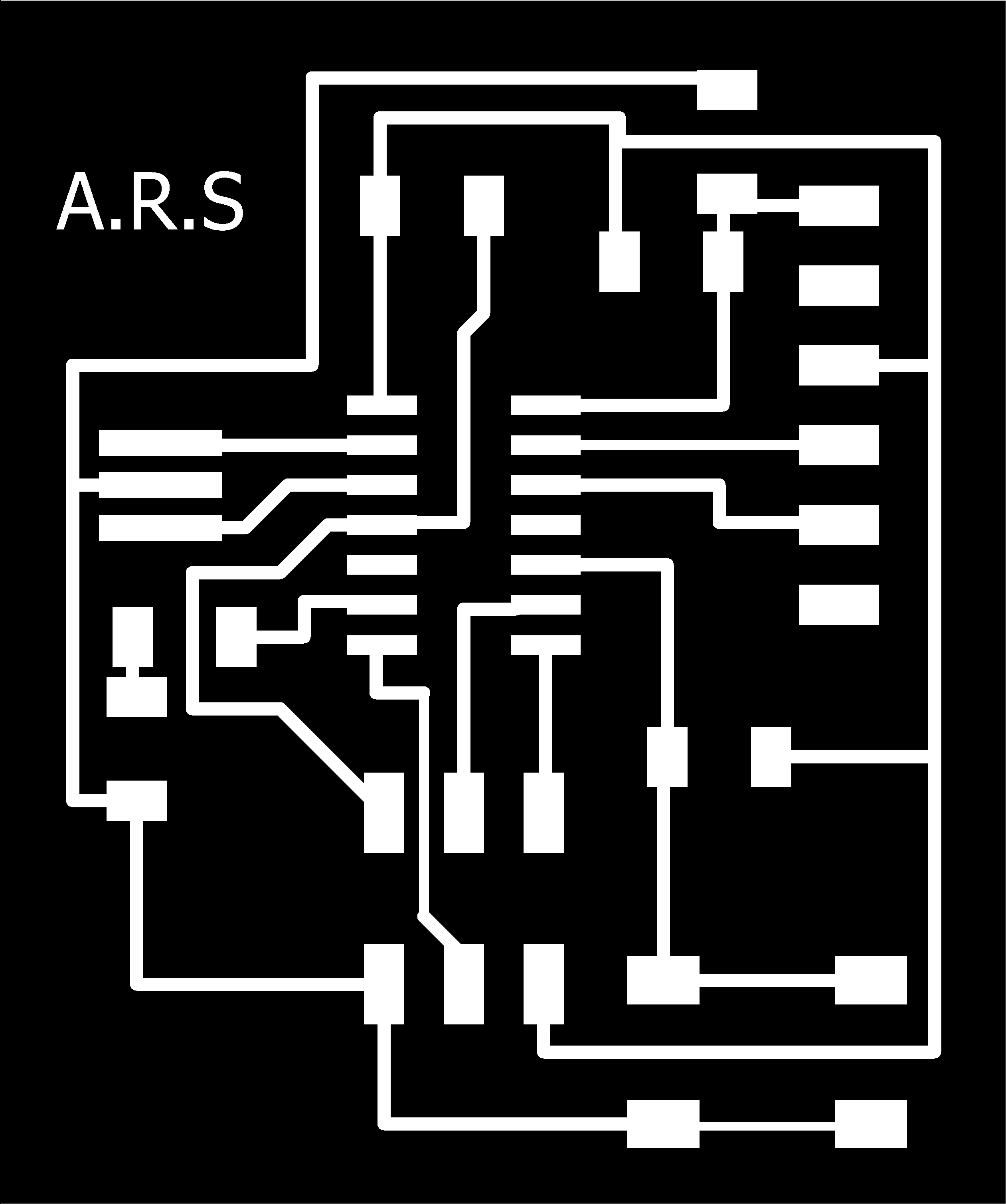
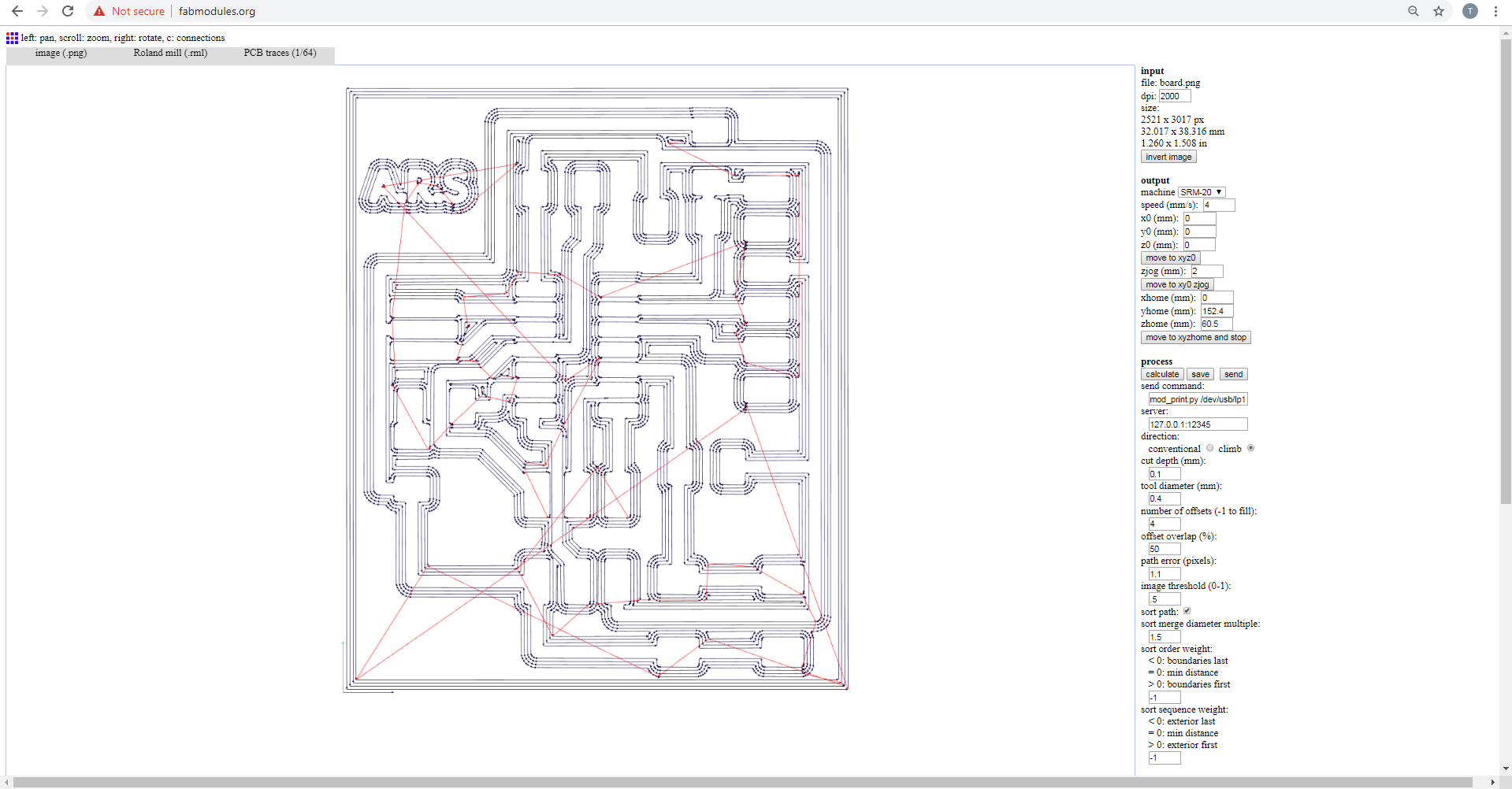
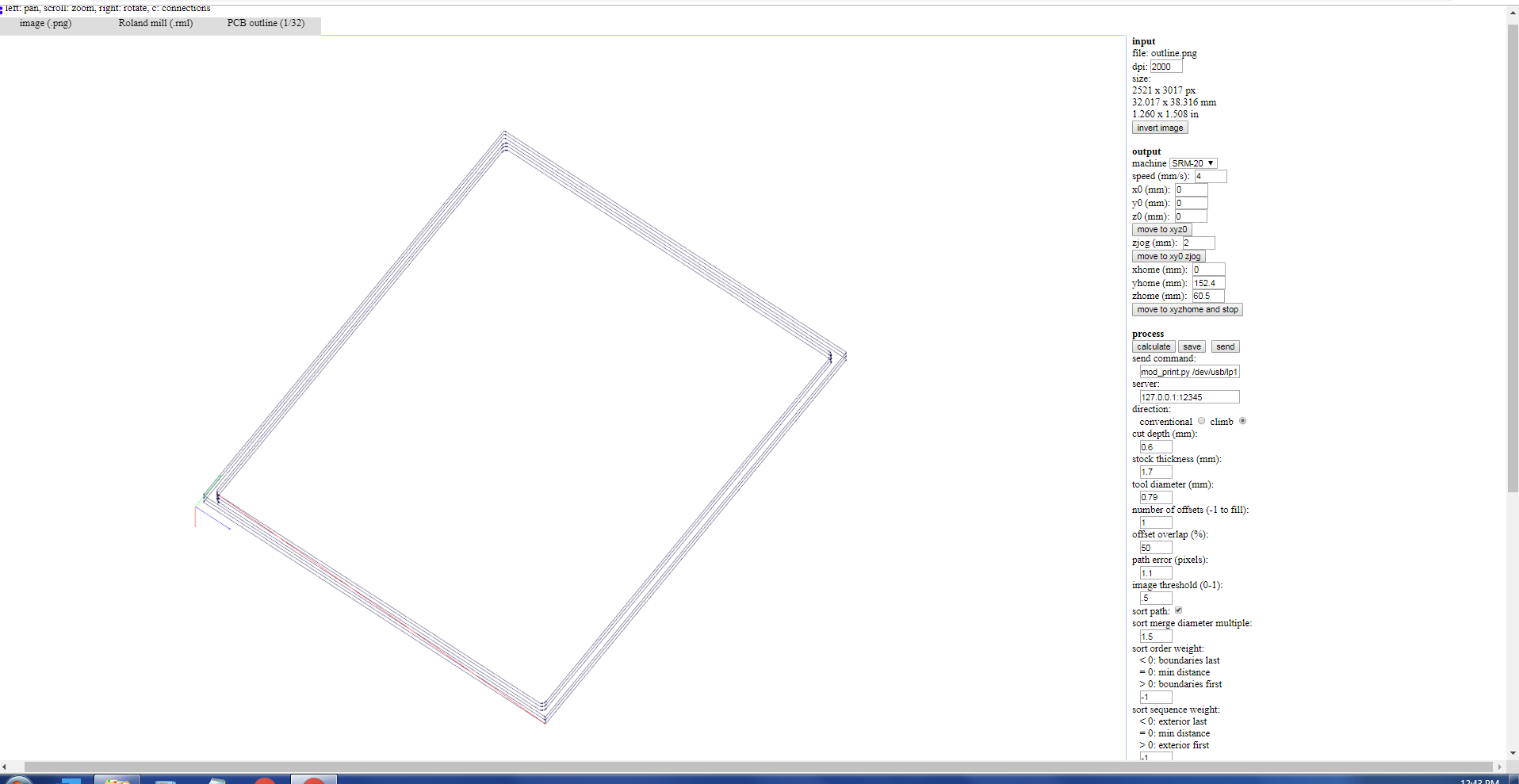
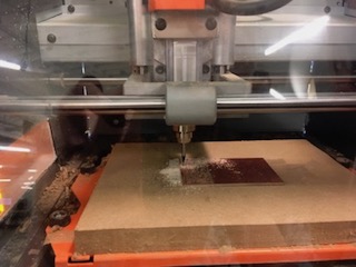
Miling
Following points shows few important things in milling process.
Remaining process is the same as we have done in Week 4 (Electronics Production)
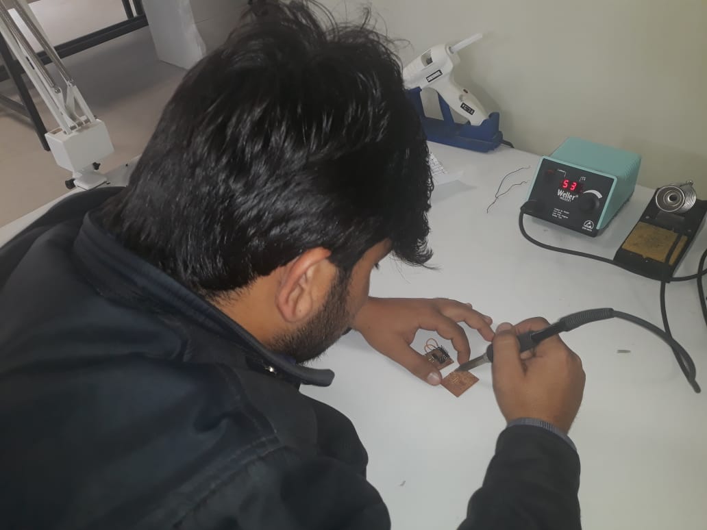
Soldering.
I improve my soldering skills in this week , Apart from that I go through some tips for soldering. Here is the image recommended by my local instructor for soldering. Mr Noor Ahmed Raza Pirwani

While working with soldering
Here is the picture of my final board. .
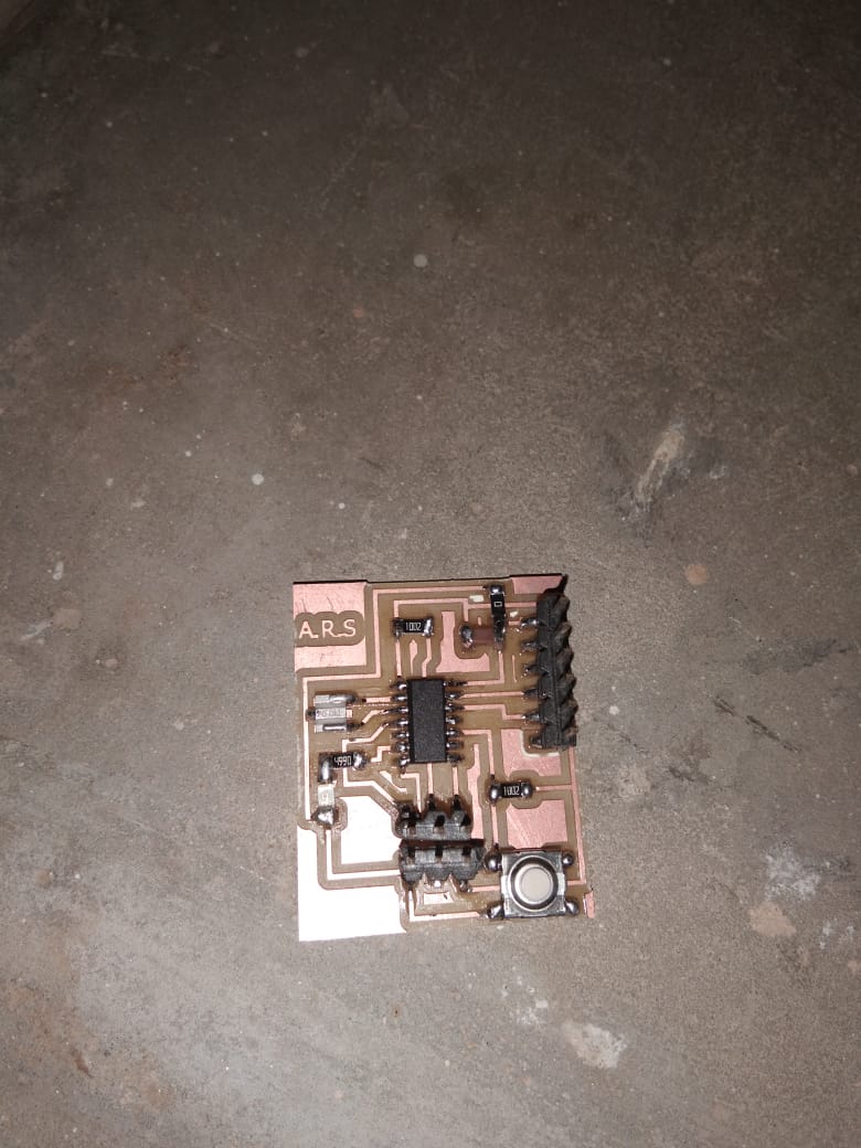
.png)