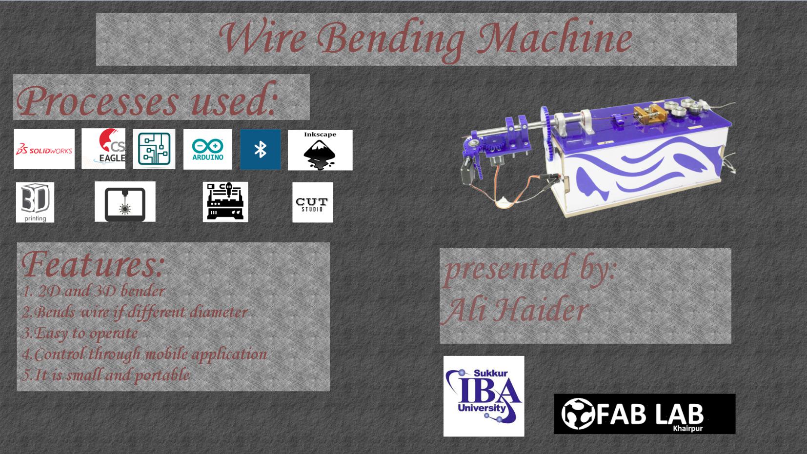
As we know that Final Project is a very important part of of Fabacademy , it includes the necessary modules of digital fabrication that we have learned so far. So, for my final project , I
inteded to make a Wire cutter , which is a very useful and efficient tool needed in our labs and as well as in market.Bacially there are alot designs and shapes of wire's design that cant be
attain easily and if once we made a piece with precise design, shape and size but we cant made produts with the same and precise shape, design and size in large number and the another main issue
is to too slow for large mumber of production.By the way, day by day every engineering line is moving on the Rapid prototyping is a group of techniques used to quickly fabricate a scale model of
a physical part or assembly using three-dimensional computer aided design (CAD) data.Rapid prototyping tools allow designers and engineers to quickly and inexpensively create functional models,
fixtures, or products. New additive technologies like 3D-printing and subtractive manufacturing tools like laser cutters and CNC mills and lathes allow fast and accurate manufacturing of many
different prototype components. These technologies allow designers to bring their ideas into the real world much faster than was previously possible.Wire bending is another emerging method of
manufacturing that has enhanced the ability of designers to make use of negative space and frames in assemblies.And if we look at the pakistani market, if there are some wire benders available in
market so those are just for the large scale or for the industrial level but there is no wire bender for the table-top or table desktop, or small wire bender. Those large and current available wire
bending tools are either very expensive, or limit the user to two dimensional structures. I believe that this market gap can be filled by an affordable, desktop scale, three dimensional wire
bender. With this in mind I were able to develop the needs that we felt were important to achieve in a prototype version of this 3D wire bender.
The project comprises of following main parts:
3D Designing
3D Printing
Laser Cut
Electronics Production
Troubleshooting - Stepper motor Driver IC, Servo motor, Input/ Output devices, Extruder of Wire Cutter
Programming
Input and Output
First of all , I chalked out a plan and strategy for completing the final project. I moved step by ste[ , from one module to the other. Initially, I studied about the existing wire cutter projects,
in this way I got a complete insight of what I will be needing in my project and which things will take more time.
3D Designing
In my project I needed to make some 3D printed parts and a Laser Cut Base part. I chose to work on Solidworks.
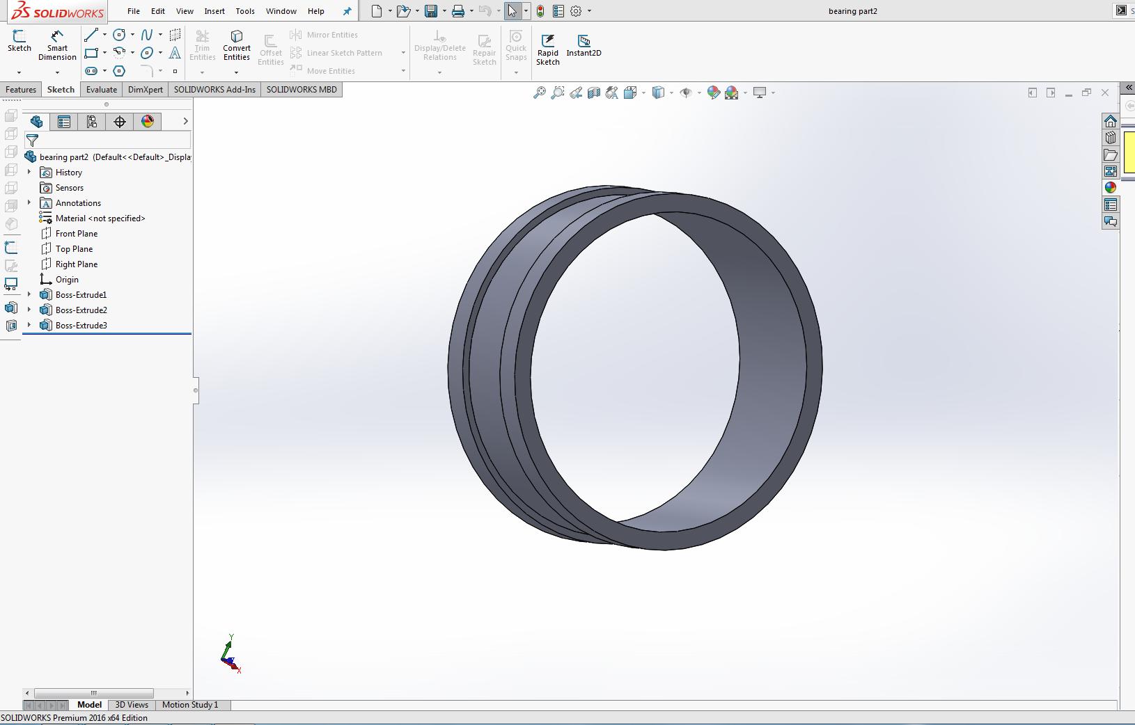
As I start on solidworks, First I design the bearing case, because its the part of the wire extruder from where I will feed wire, I need some bearing from where the wire will passs and these bearing
will make the wire straight.
I used following tools:
Sketching.
Boss Extrude.
Bearing Case
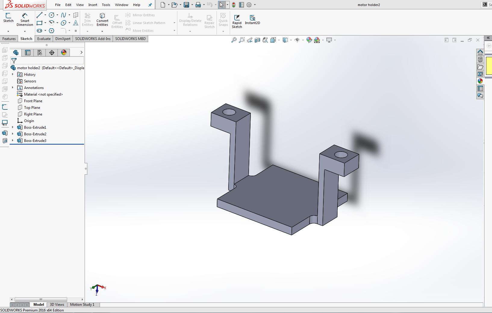
Next I design a case as a motor holder, for the motor that will feed wire. Bearing Case
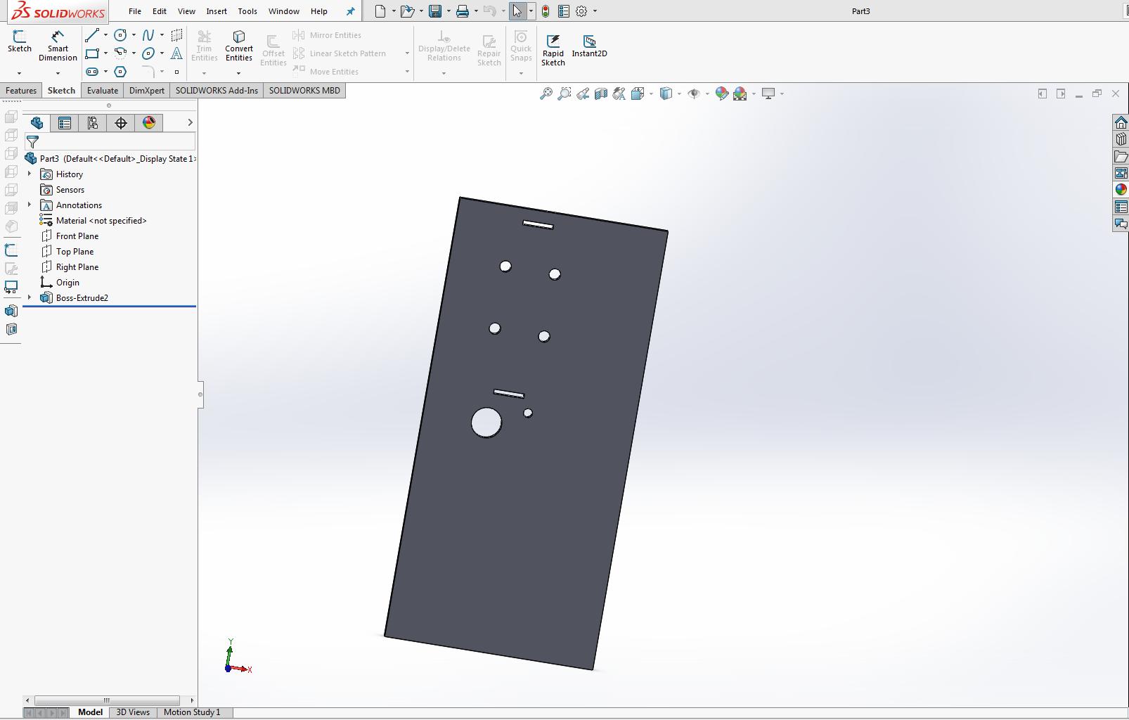
After this I designed the base plate where I will place bearing and stepper motor.In this just made a sketch, extrude it and again add on sketch and made extrude cut on it. base plate
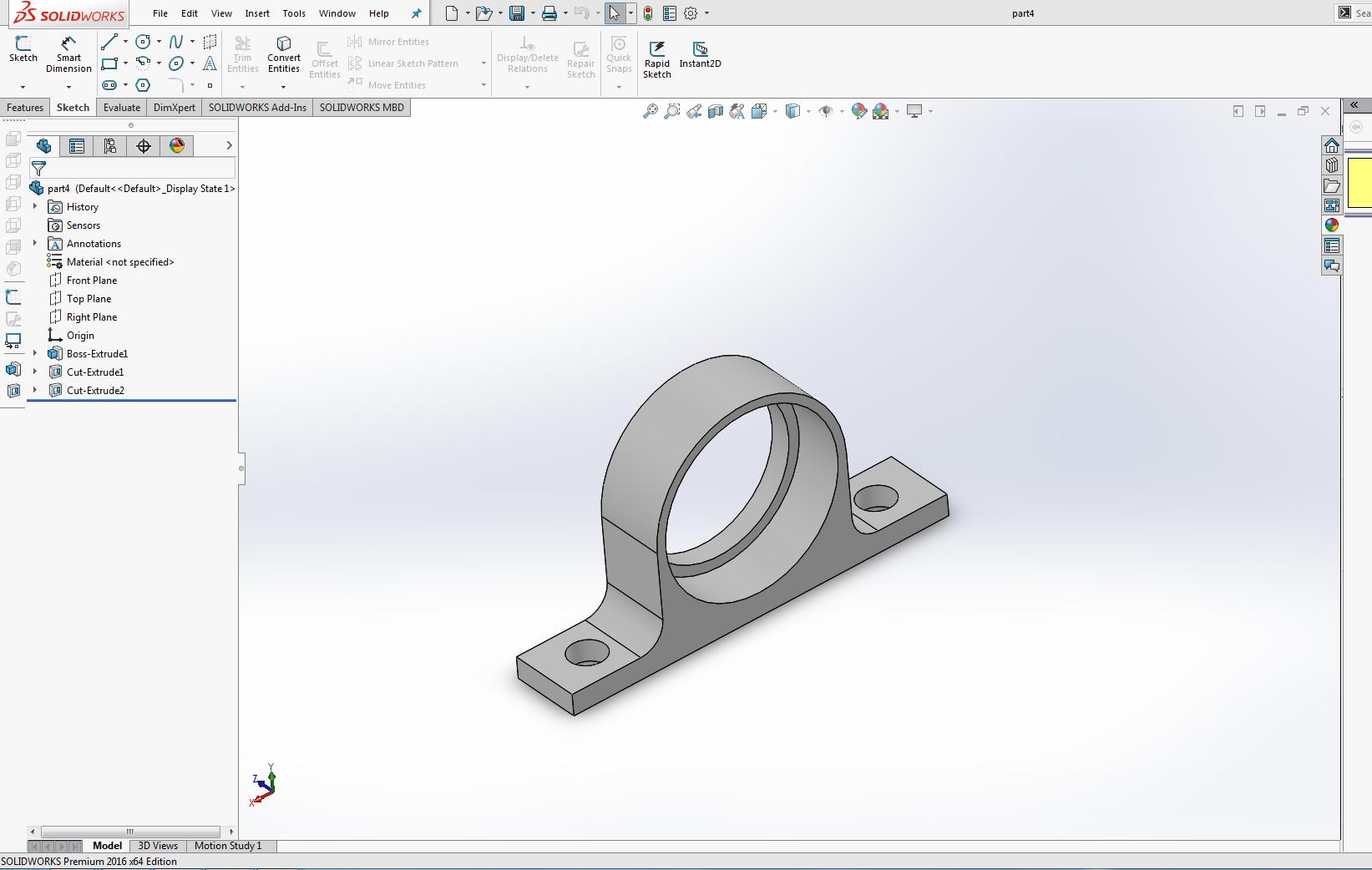
Next I made the following part, in this part I fixxed a bearing and a straight rod in its inner side, and from this straight rod the wire will be feed to the bender area. '
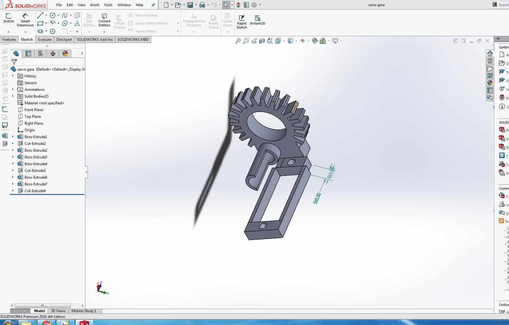
Designed a gear with rack and pinion for the servo. Part
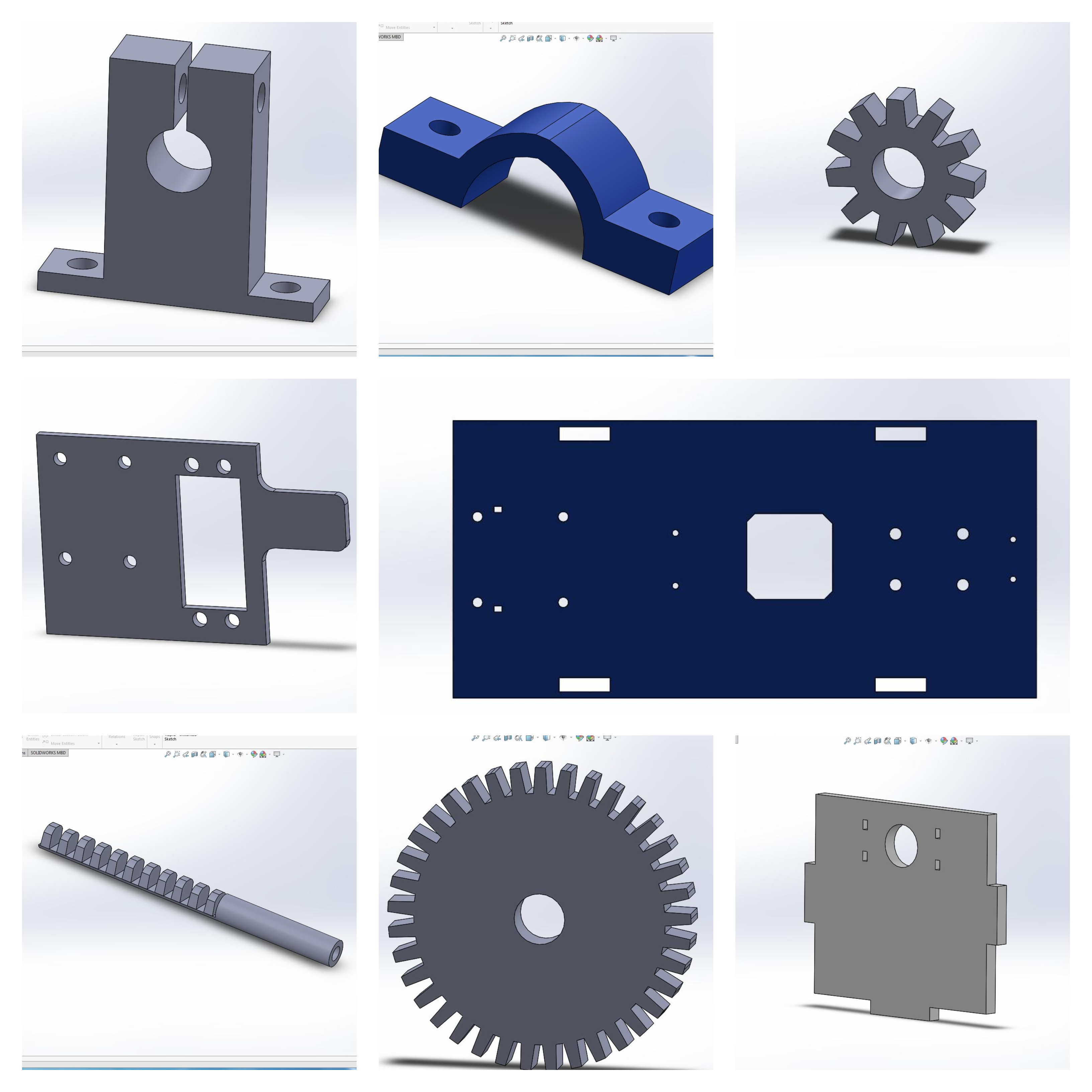
Designed some other parts of the project in solidworks. In this collage the small gear is as a pinion and there is a rack for the servo, there is base plate in blue color for the wire feeding purpose
and the large gear is for the z-axis stepper motor. Different parts
After completing the designing I used diffetent machines for the different parts.I used the 3D-printer for some parts adn used laser cutter for some parts and cut the main body in
Shopbot cnc machine.
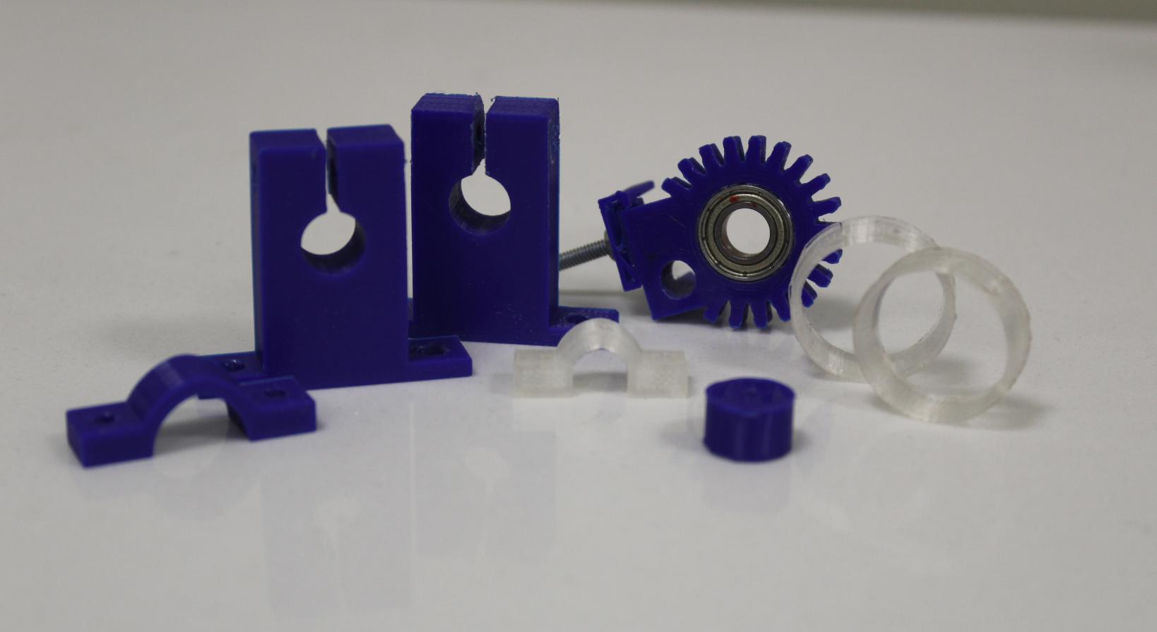
In the following images you can see the finished parts.
3D-printing
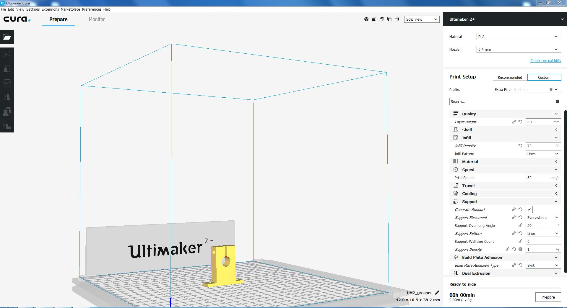
For the 3D-printing we are using the Cura sofware and here we are preparing 3D model in Cura for 3D-printer and generating the g code file. Cura
So here are the finished 3D-printed parts, these are the all 3D-printed parts that are used in the project. 3D-printed parts
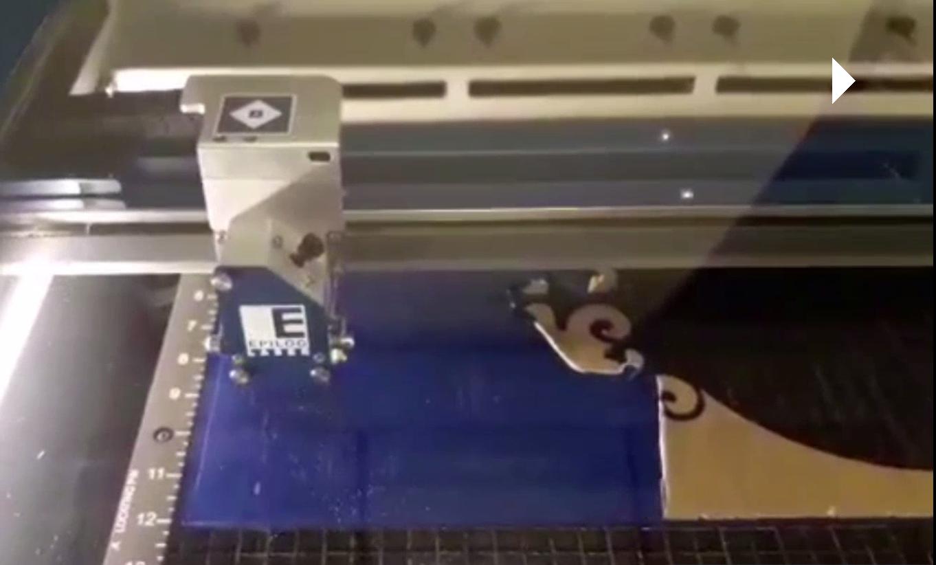
Laser cutting
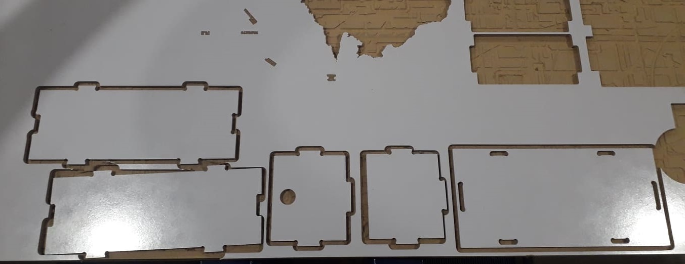
These are the laser cutted parts, we have cut these parts on the Epilog laser cutted, we did set the power 90 and speed 10 for all the parts and the blue acrylic that is used is 6mm sheet. laser cutting
All the laser cutted parts. Laser cutted parts
CNC Machining
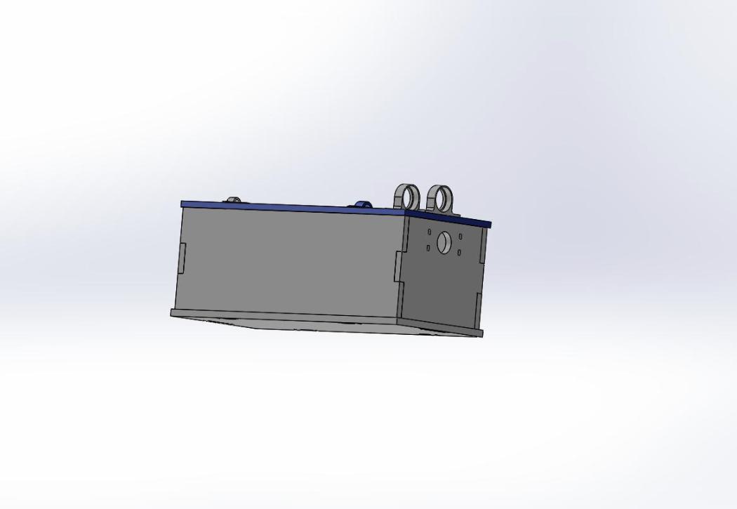
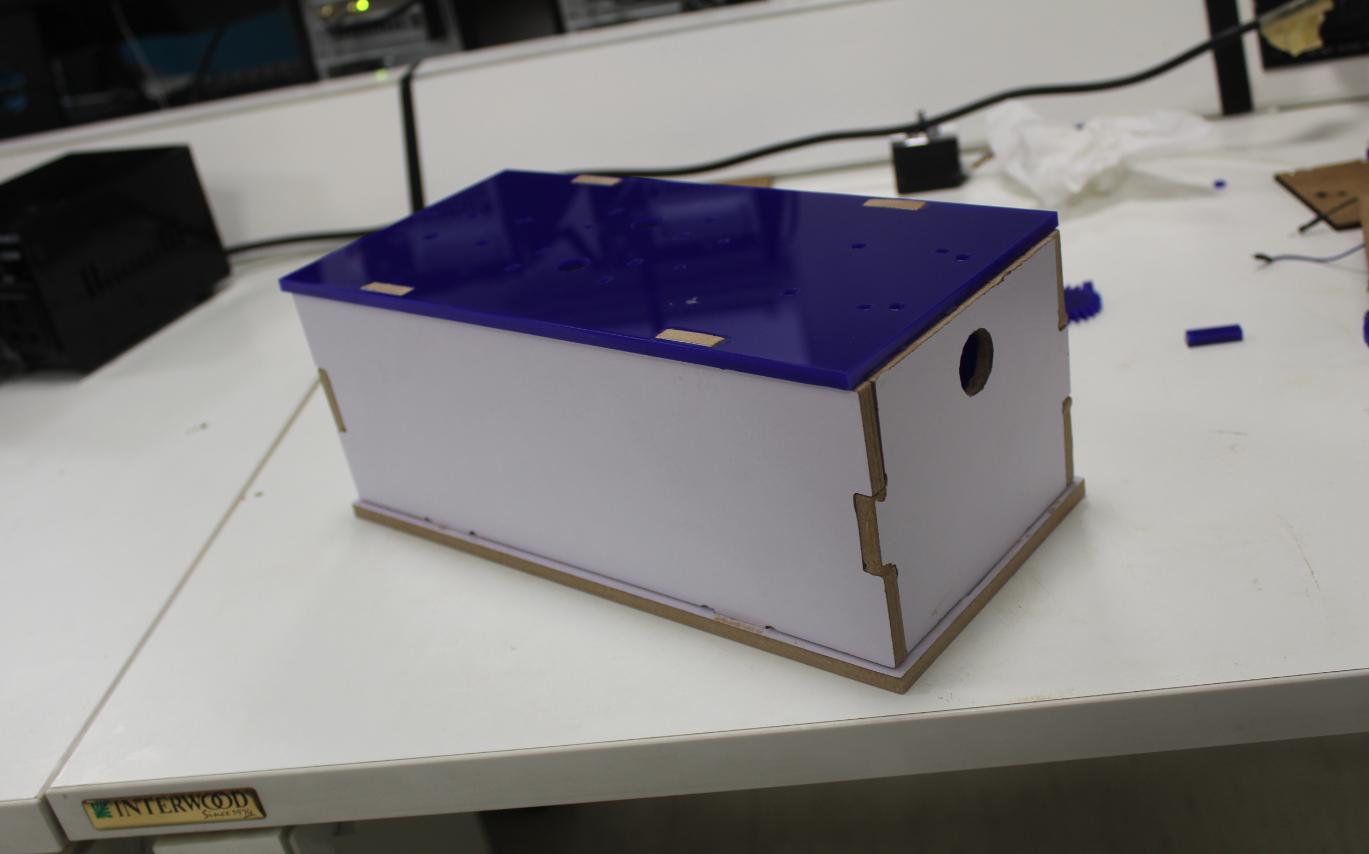
The main body designed and assembled in solidworks. It is a completely press fit body.
After desigining we did cut the main body on CNC Shopbot, I generate the toolpath on Vcarve sofware for the machine, set some dog-bones on corner for pressfit, adjusted the
tool 1/4" down-cut, set the oustside-cut for the whole body except the hole(used inside-cut), stepover 0.1, sprindle speed 14000 and feed rate 3.0 for the machine. and the cutted result is here.
After this we assembled the body. The Assembled body
After this we assembled all the 3D-printed, laser cutted and CNC cutted parts. Other Assembled parts
Vinyl cutting
I cutted some random design on blue Vinyl with the help of Roland Vinyl cutter and pasted it on the main body. Other Assembled parts
Failure attempts
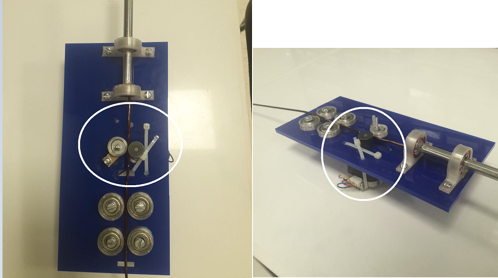
After this I went for the further process and cut the base plate with laser cutter and set the feeder stepper motor and straightner bearding on it.
Base plate
But in this part there was a problem, it was not feeding wire properly and sometimes it was not feerding the wire and making jerks. I tried alot to resolve this problem but I was failed in all attempts.
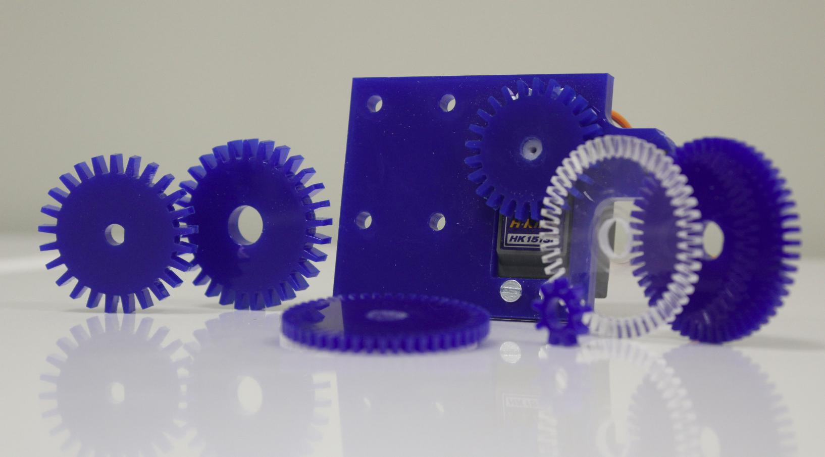
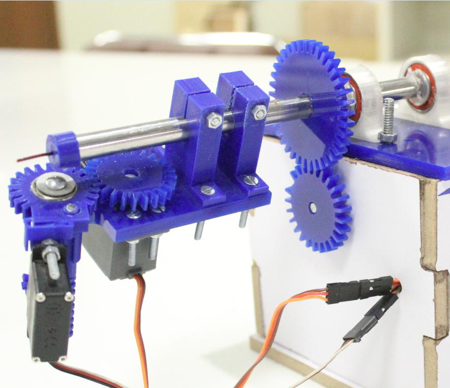
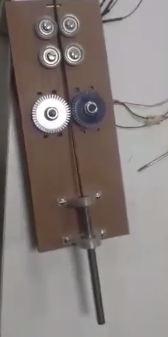
Next I tried another design and for the feeding purpose and I set two stepper motor and designed gera for the motors, you can see in the image, the gears are the laser cutted gear and are set according
to the diameter of wire.
2nd attempt
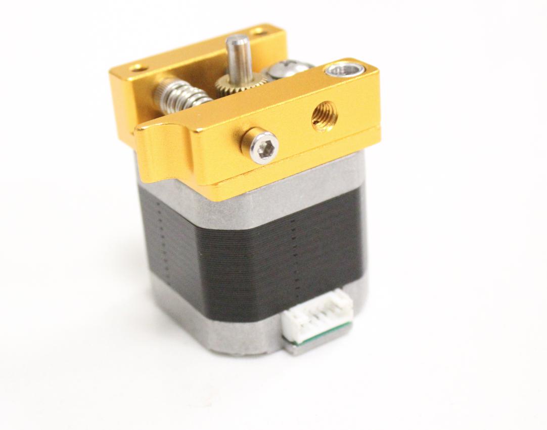
It was also not a successful attempt because it was moving the wire, the but was not moving the wire properly and making fluctuations during moving.So I moved to the next option and I selected the
stepper wire extruder.
Wire Feeder
The materials that are used:
3D-printed parts: PLA
Laser cutted parts: Acrylic(6mm)
Main body: MDF
Rod: Stell
Screws: 4mmdia
Wire: copper
Electronics
Microcontroller: atmge328p
Bluetooth module: hc-05
Stepper driver: A4988
Servo motors
Stepper motors
Jumper wires
Electronics systems
The main microcontroller circuit board I am using is atmega328p, which is supporting the A4988 stepper driver to control the motors and also atmega328p making the communication possible
between the hc-05 and mobile application.Here are some features suppports by this board.
Support Programming from FTDI Cable.
One general purpose button connected with Pin2 of Arduino.
Dedicated I2C Connector.
Dedicated Serial Connector.
General Purpose 4 Analog Pins A0, A1, A2 and A3.
General Purpose 8 Digital Pins in which 5 pins are PWM~. Pin3~, 4, 5~, 6~, 7, 8, 9~, 10.
LED is connected with Pin13 to work with LED_BUILTIN codes.
Dedicated 2x3 ISP Pins.
Controller RESET button.
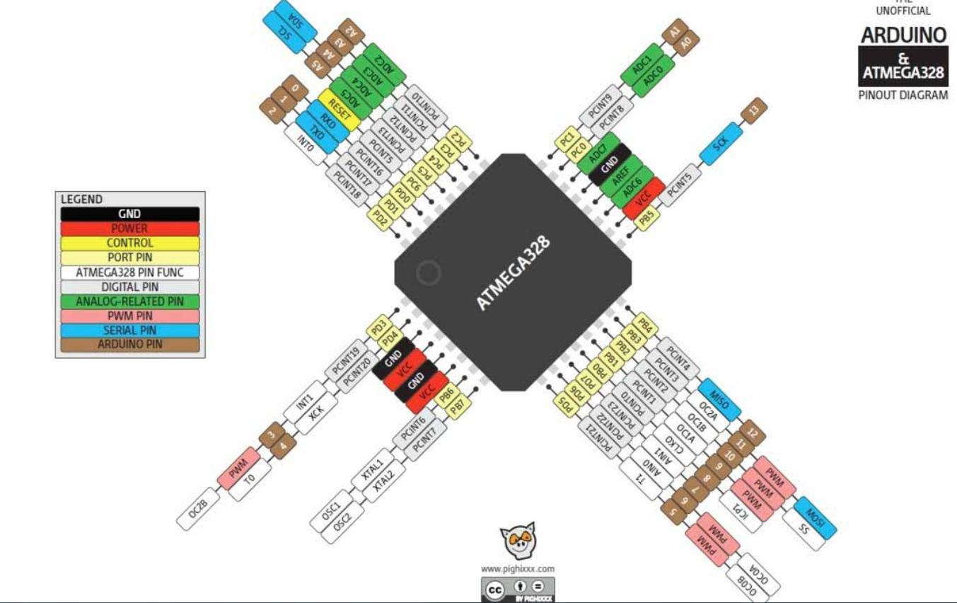
The pinout diagram of atmega328p. atmega328p
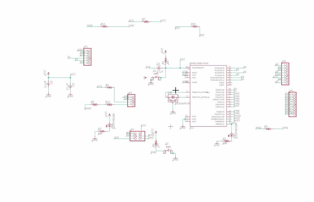
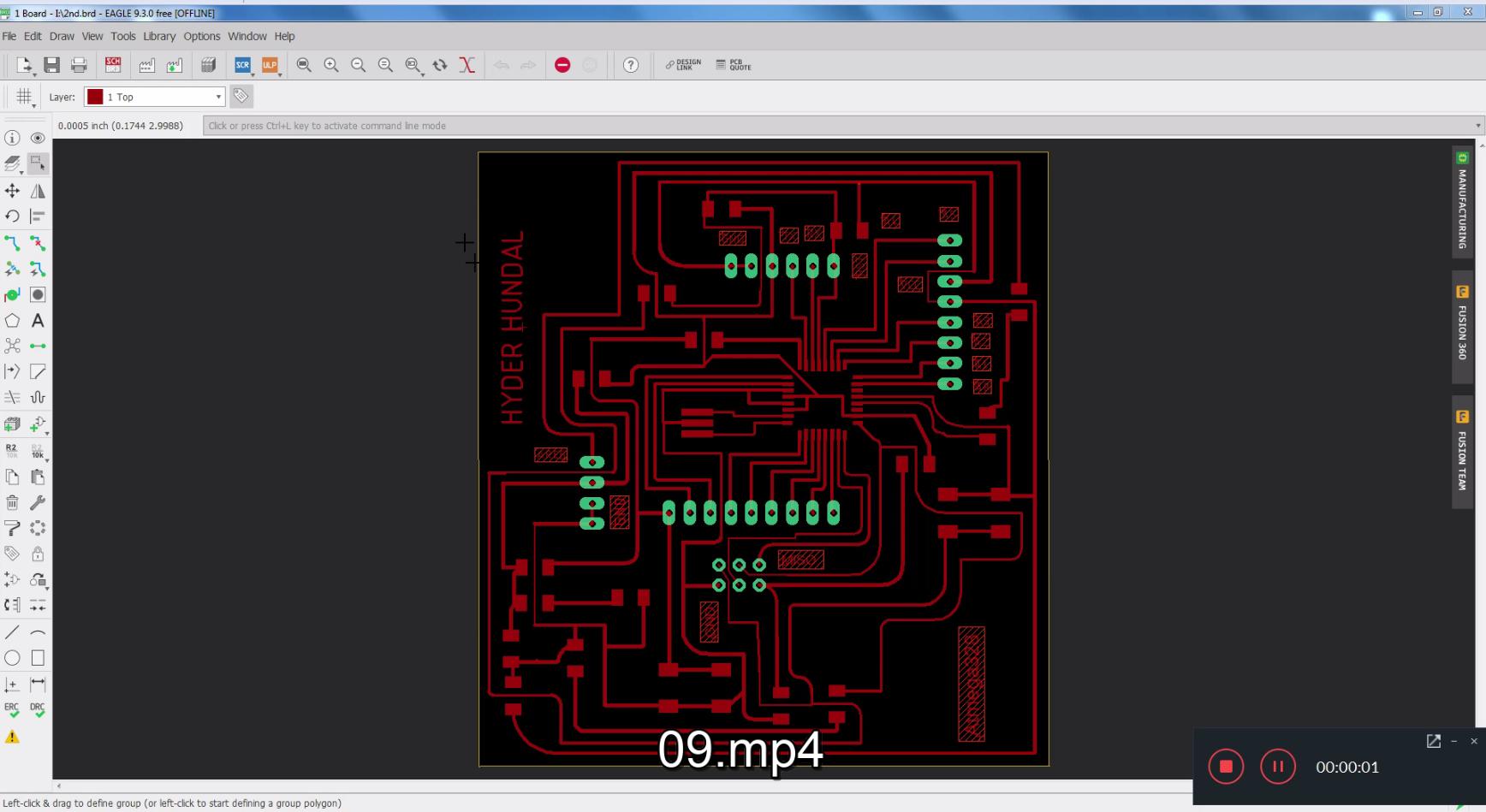
I started from the desigining of board in eagel.
Eagle interface
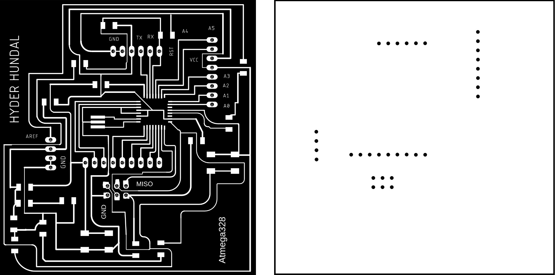
The png files of the traces and drills of the board, after this We milled the board and soldering the components on it.
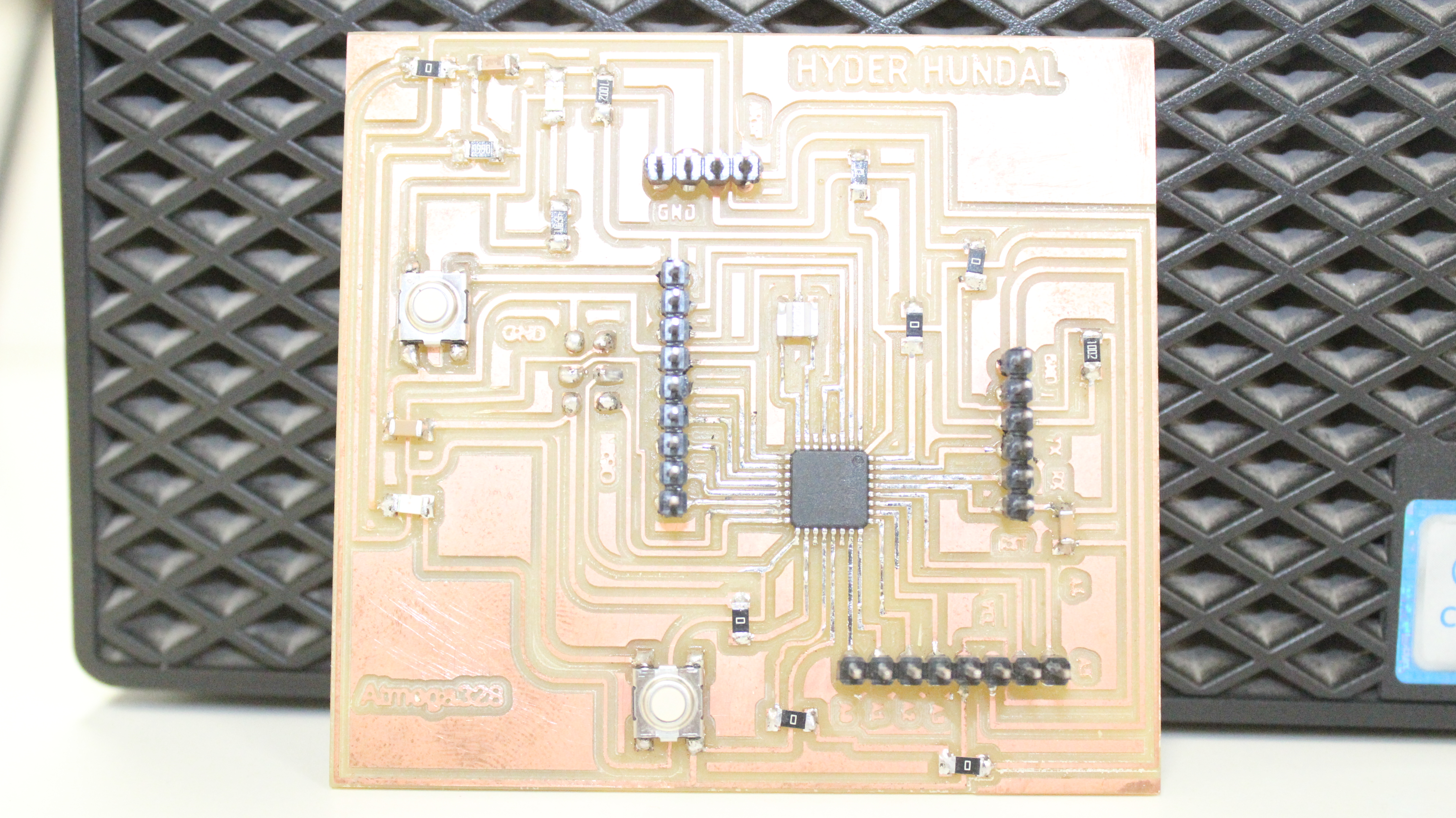
And finally the board is ready, but I did a mistake during the desigining, I actually made the wrong connection of the TX and RX. I connect the RX of FTDI with the RX of board and also connect
the TX with the Tx of the board. Where as the I should had to connect the FTDI'S TX with the RX of board and Rx oF FTDI with TX of board. so for I have to use the jumper wires during uploading
the code evey time.
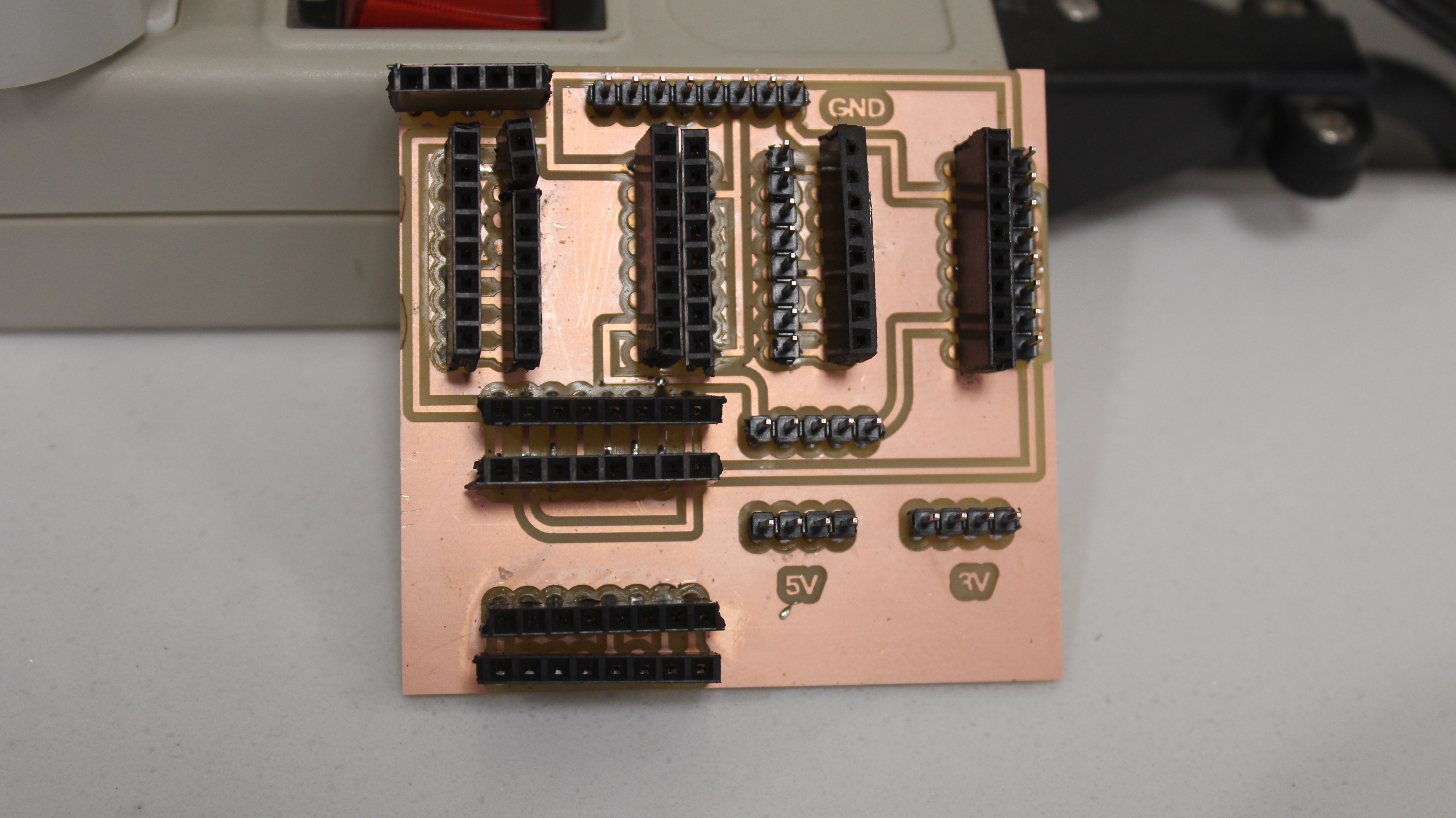
I also designed, milled and soldered another board for the stepper drivers.
Programming the board
To program a board I need an ISP programmer, I made one developer board in Electronics Production Week.
I am using Arduino IDE for programming my board. Before programming the board first it is required to burn bootloader in it. For setting up Arduino IDE to work with FabISP I mentioned in
detail in Embedded Programming Week. The bootloader burn in board using FabISP which is 1 time process then after that I use FTDI Cable to program my board.
Connect 328p board with FabISP and connect it with PC.
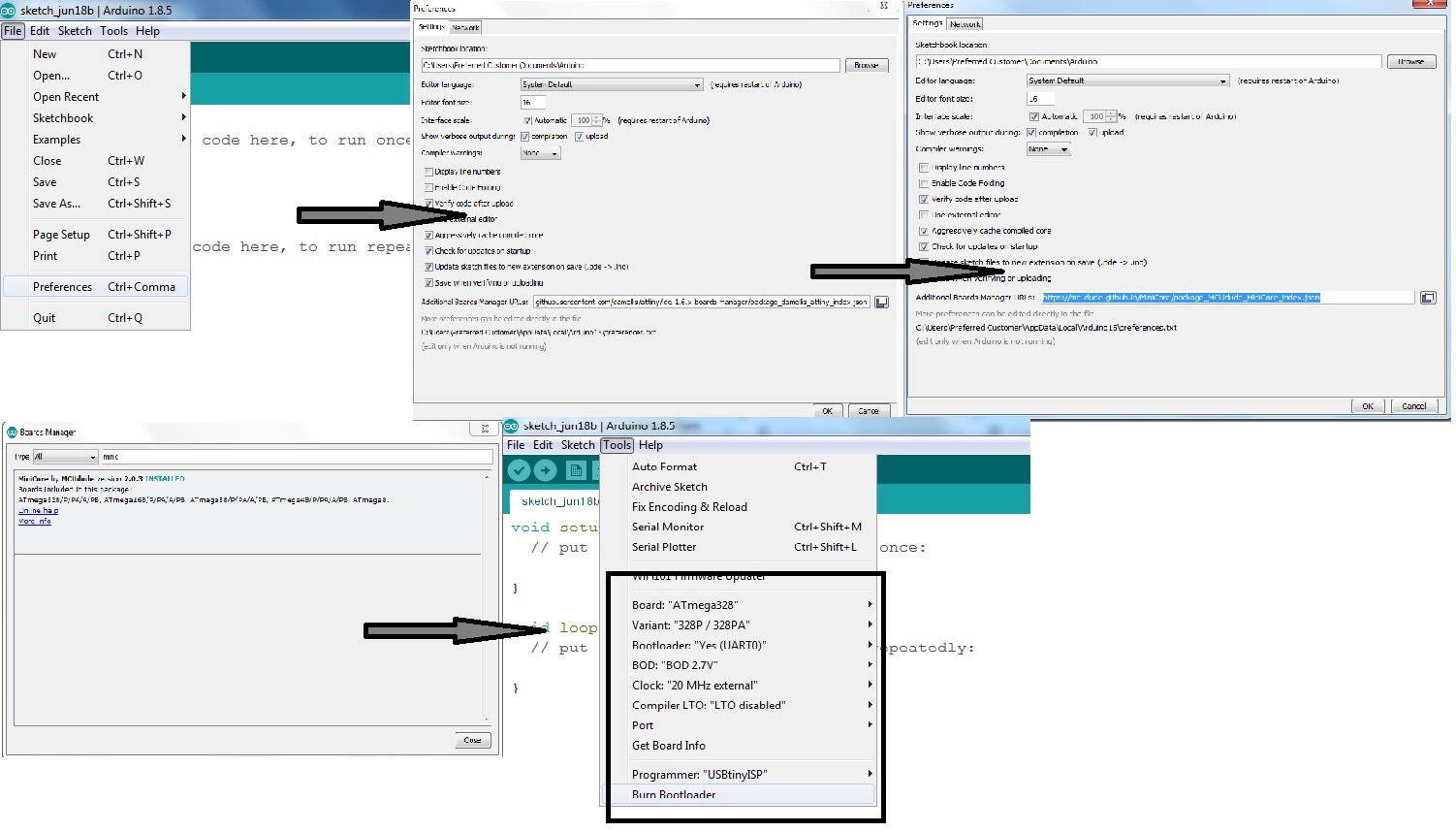
I found this core: MiniCore helpful to work with my 328p board. So first copy and past this link "https://mcudude.github.io/MiniCore/package_MCUdude_MiniCore_index.json" into File >
Preferences > "Aditional Board Manager URLs".
Now go to Tools > Boards > Board Manager... and install MiniCore by MCUdude
These are the settings which I mentioned below before burning bootloader, set it up and click Burn Bootloader
After burning bootloader successfully now we test board with Blink Code which is present in Arduino examples, to check either it is working or not. Here we have to remember on thing that when we press the
upload button after this wait for 2 to 3 second and press reset buttton of beaard otherwise the code will not be upload in the board.
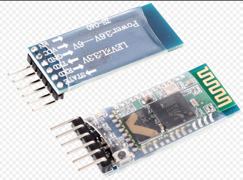
HC-05 module
HC-05 is an easy to use Bluetooth SPP (Serial Port Protocol) module, designed for transparent wireless serial connection setup. The HC-05 is a very cool module which can add
two-way (full-duplex) wireless functionality to your projects. You can use this module to communicate between two microcontrollers like Arduino or communicate with any device with Bluetooth
functionality like a Phone or Laptop. The module communicates with the help of USART at 9600 baud rate hence it is easy to interface with any microcontroller that supports USART.
hc-05 module
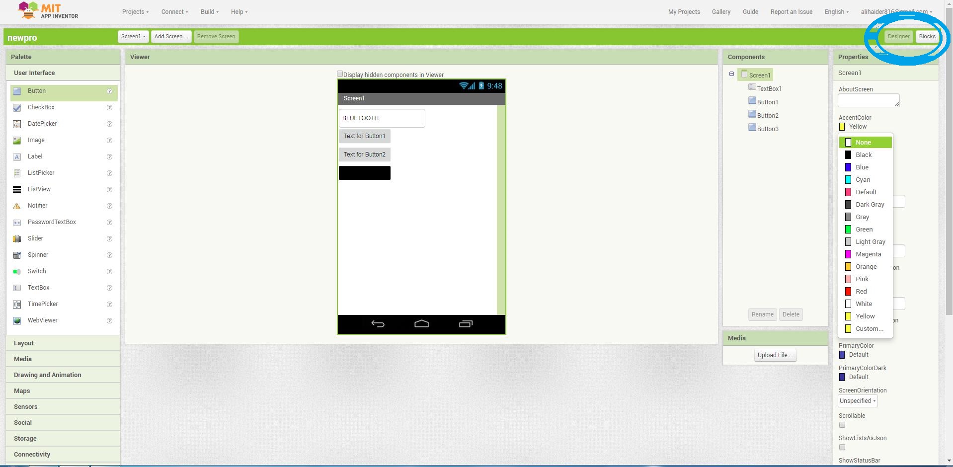
Mobile application
After this I made a mobile application to the operate the wire bender. Through this app I will command the bender machine, the mobile application will be connect to the machine with the help of
bluetooth(hc-05) and I will send the pattern or shape I want. In this application I have set 3 different patterns/mode(Triangle, square and zig-zag).
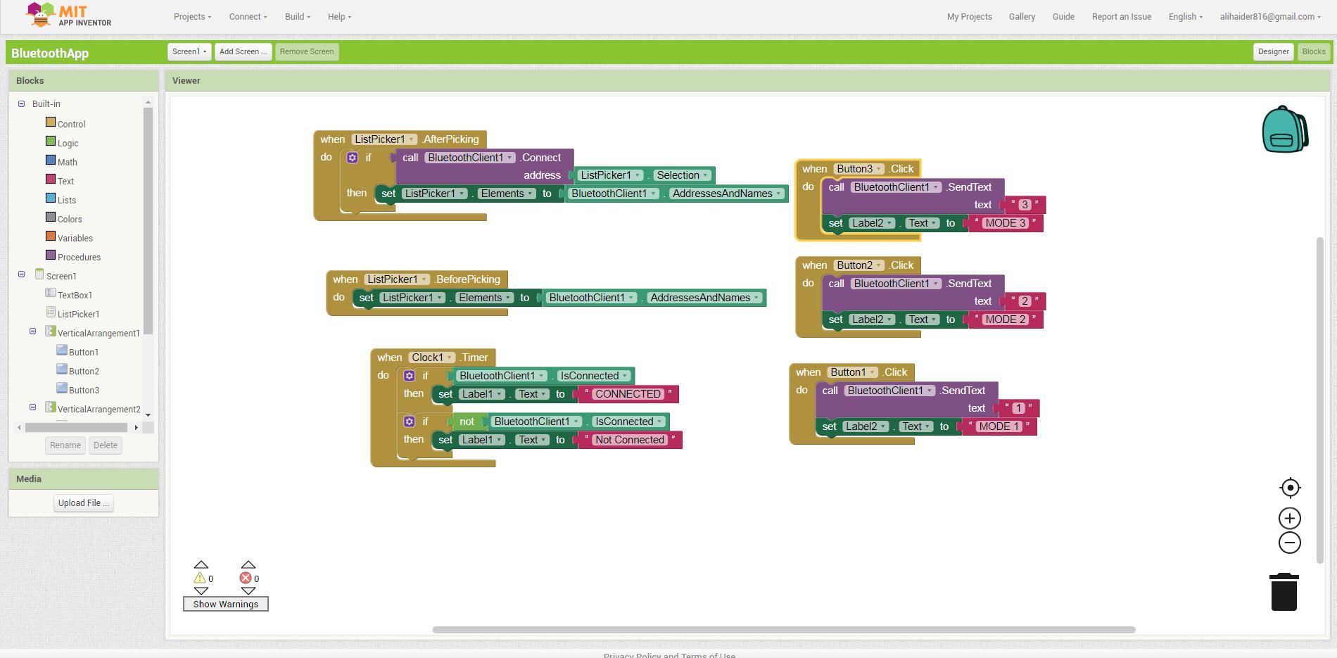
Making an app
Desigining the application using the different blocks. Desigining
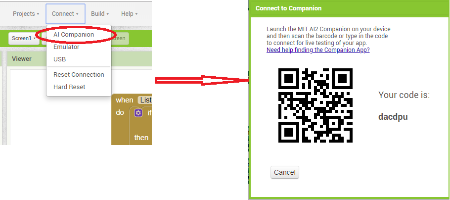
I used the AICompanion app, so for that we have to start it from connect menu, and then click on AI Companion.
Once the AI Companion is clicked it will launch the barcode screen.
After this, you have to launch the AI Companion app on mobile and scan the QR code and then connect with code, and your application will be launched. But there is one condition, your mobile
as well as the computer must be on same network otherwise this function wont work.
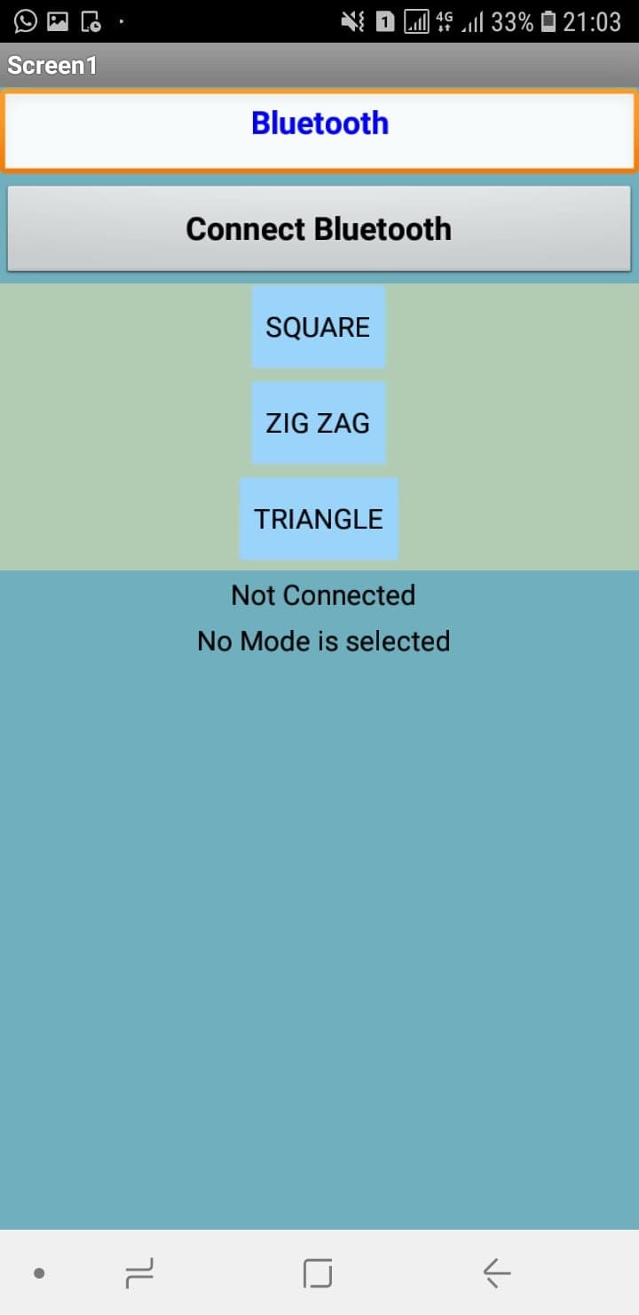
So this is the final mobile application screen.
After the mobile application I did communicate it with the HC-05 bluetooth module, using the pins TX and RX to trasfer and receive data, You can see in the mobile screen preview that I have set
some different modes like triangle, Square and zig-zag. when we will just press any mode it will send data to the HC-05, through HC-05 the microcontroller atmega328p board will control the motors
and all and will make the pattern or mode.
Programming
After this I write a code on Arduino IDE and upload it to the atmega 328p. In program I also used the MISO pin of board as a PWM pin for the servo motor to operate it because there are no
more PWM pins in it. Arduino IDE
In the following video you can see all the processes that are used and a quick demo.