For this weeks group assignment we sent a message between to projects. The documentation can be found here.
For this exercise I decided to try out communication via the I²C protocol. I²C is a serial bus protocol, which means that all devices are connected to a single bus. This consists of a clock line (SCL), a data line (SDA) and a common GND. One device acts as a master providing the clock signal and initiating communication. It's also possible to use multiple masters. All other devices are slaves, which can be separatly addressed using a 7 bit address.
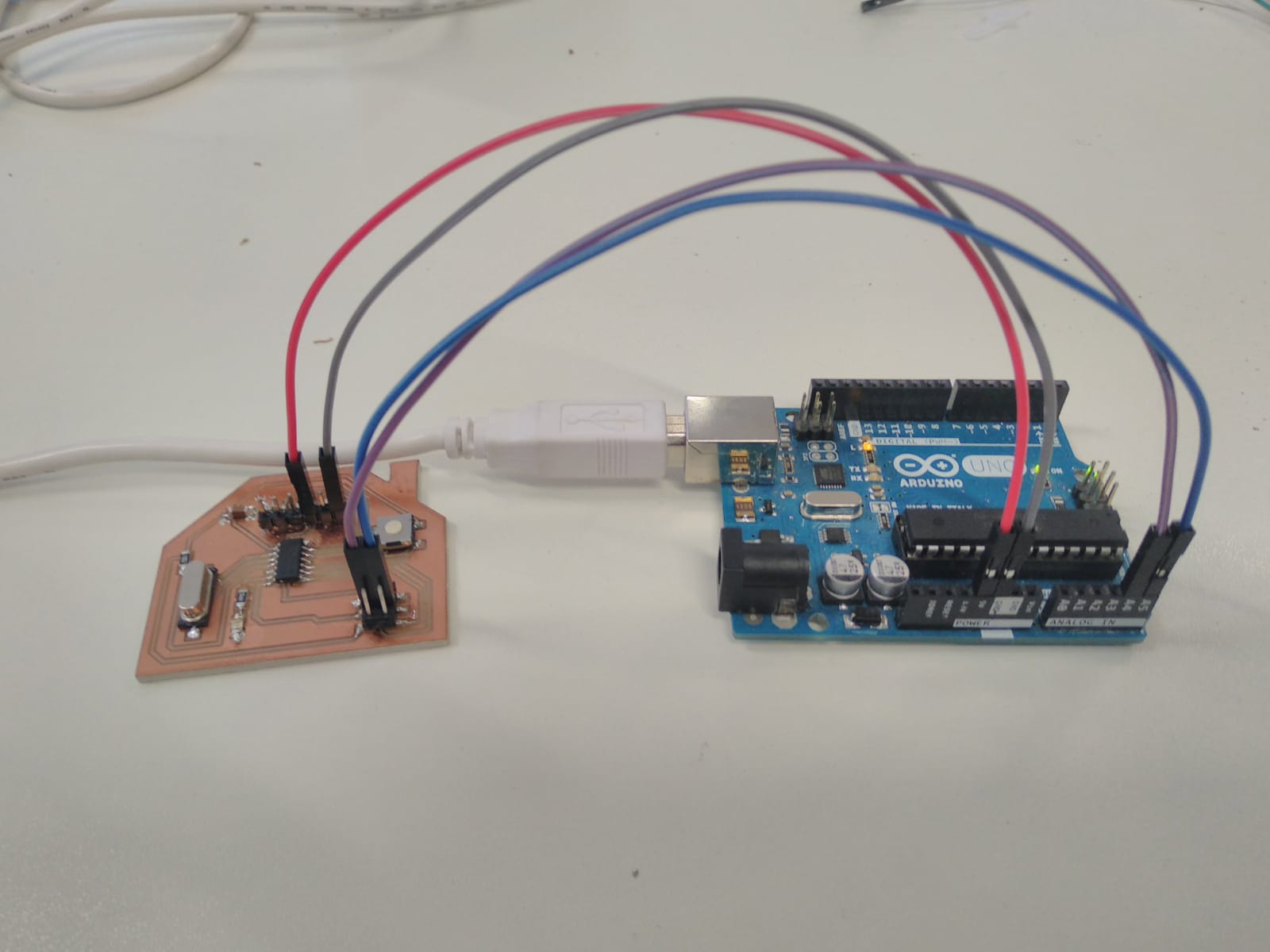
For this I used two boards I manufactured before as a recipient that blinks whenever an 'a' is received over I²C and an arduino as the sender.
For my own board I wrote the following code:
#include <twi.h>
#include <TinyWire.h>

void setup() {
  TinyWire.begin(10);                // we listen with the address 10
  TinyWire.onReceive(receiveEvent);
  pinMode(A7, OUTPUT);
}

void loop() {
  delay(100);
}

void receiveEvent(int foo) {
  while (TinyWire.available() > 0) {
    char c = TinyWire.read();
    if(c == 'a'){
        digitalWrite(A7, HIGH);
        delay(500);
        digitalWrite(A7, LOW);
    }
  }
}
Whenever the controller receives an 'a' it will toggle the state of the pin PB7.
Because I'm using the TinyWire library (the 2017 update by lucullus) I had to download it manually and add it as a ZIP library.
The I²C Master is is the one who is running the actual loop for blinking continously. This program uses the default I²C library that comes with the arduino IDE.
#include <Wire.h>

void setup() {
  Wire.begin();
}

// the loop function runs over and over again forever
void loop() {
  delay(2000);                       // wait for a second
  Wire.beginTransmission(10); // transmit to device #10
  Wire.write('a'); // sends x
  Wire.endTransmission();
  delay(2000);                       // wait for a second
  Wire.beginTransmission(9); // transmit to device #9
  Wire.write('a'); // sends x
  Wire.endTransmission();
}
Now I connected the SCL and SDA pins of the ATTiny to pin A5 and A4 of the arduino. I also powered the board from the arduino, that way I already had the common GND needed for I²C communication.
Next I connected a second board to the network. The schematics for the board can be found at hello.sch and hello.brd.
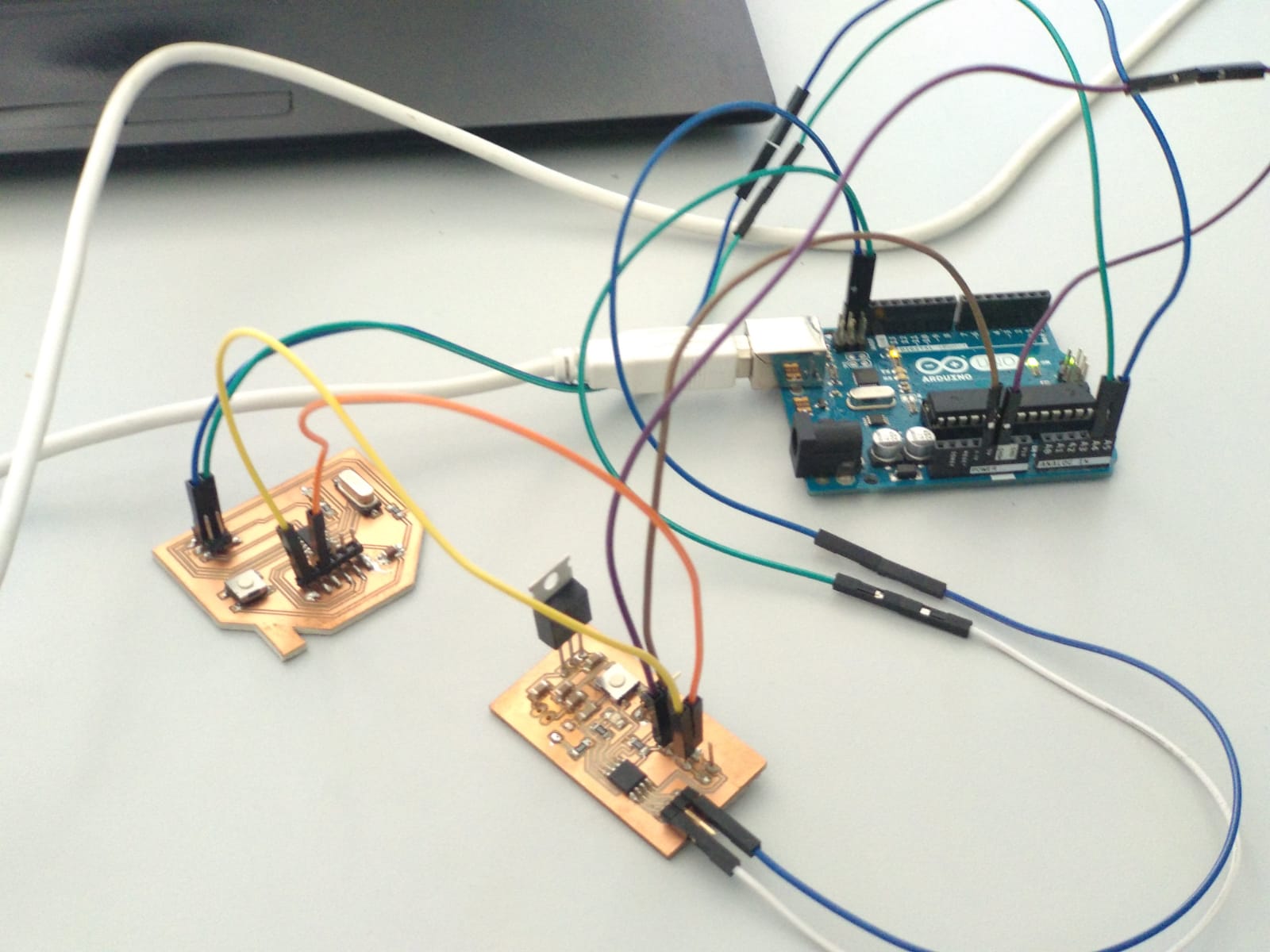
This board uses an ATTiny45 instead of an ATTiny44, but the same TinyWire library can be used. All I had to change was the pin number (from PA7 to PB4) and the I²C address (from 10 to 9). I used this board to provide power to the first board, so they share the same GND. At first communication for both boards stopped working when the new one was connected. It turned out that the LED that I had connected to the SCK/SCL pin was introducing too much resistance, disturbing the I²C communication. I quickly desoldered it and now everything worked fine.
⬅ Back to overview