For this weeks assignment we used an oscilloscope to probe analog and digital input devices. The full documentation can be found here.
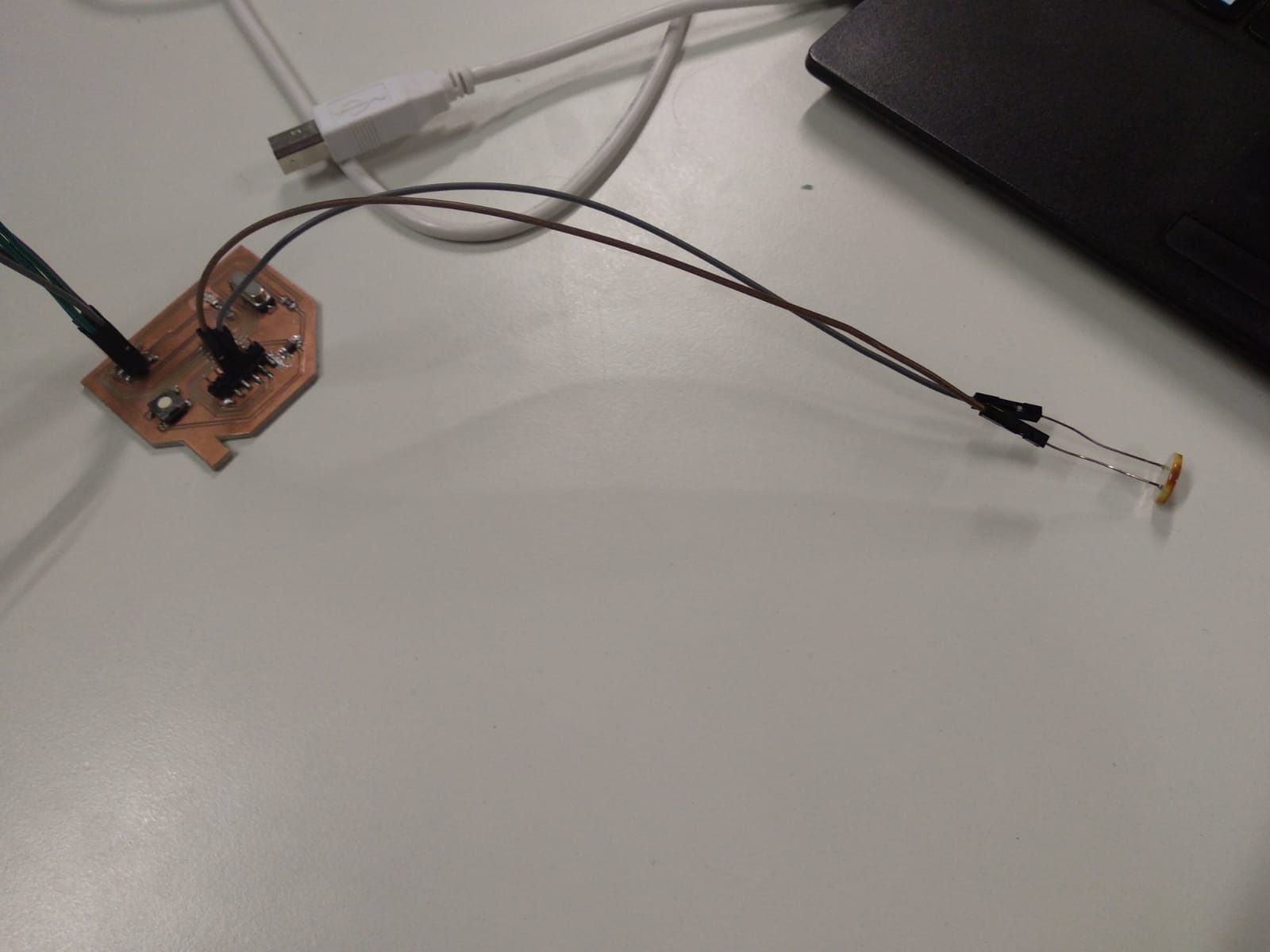
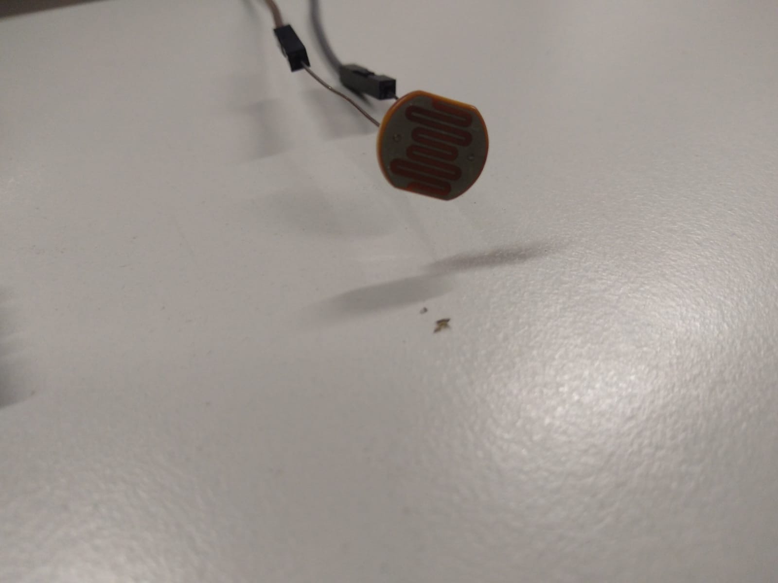
The first sensor I tried out was a photoresistor, which decreases it's resistance with increasing light. First I connected it to a store-bought Arduino to check the range of readings. I received values between 1000 and 1023, which is the maximum value of the analog input. I might could have spread the value range by adding an additional resistor, but as I simply wanted to distinguish between "light", "some light" and "no light" this was already sufficient.
void setup() {
  pinMode(PA0, INPUT_PULLUP); // Set pin to input mode and activate internal pullup resistor
  pinMode(PA7, OUTPUT);
}

void loop() {
  if(analogRead(PA0) == 1023){ // Check if we are at max value
      digitalWrite(PA7, LOW);  // LED off
    }else if(analogRead(PA0) > 1020){
      digitalWrite(PA7, HIGH); // LED blinking with 500ms delay
      delay(500);
      digitalWrite(PA7, LOW);
    }else{
      digitalWrite(PA7, HIGH); // LED permanently on
    }
}
Setting the pin mode of the pin PA0 to "INPUT_PULLUP" activates the internal pullup resistor of the ATTiny44.
ex11-photores from Florian Schäfer on Vimeo.
The second sensor was a DHT11 humidity sensor. My naive approach was to just hook it up to a pin and start measuring the voltage it outputs. This does not work. The sensors output is not analog but digital.
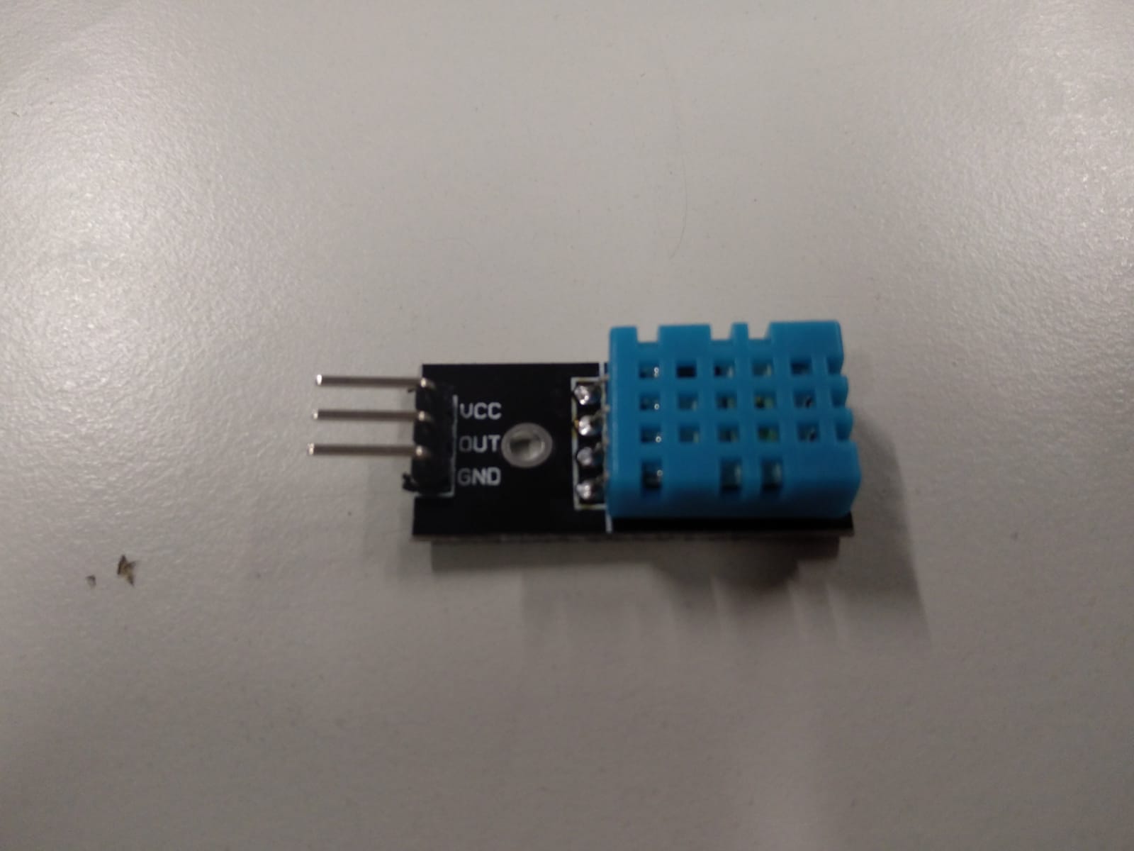
A detailed description of the communication protocol can be found in the datasheet. Basically it sends 16 bit humidity data, 16 bit temperature data and an 8 bit checksum every time it receives a start signal from the microcontroller unit. To quickly get it up and running I used the public domain DHTLib and an Arduino Uno.
But at first both sensors we had at the FabLab only returned values of -999. The temperature at the FabLab at that moment was rather mild, so I suspected an error. After reflowing the solder points on the sensor board and adding some additional solder to the connections it started to work and more plausible temperature and humidity readings showed up in the serial monitor.
Later I modified the library to print out the bits instead of integer numbers. In the group assignment we compared these readings to the ones from the oscilloscope probe. More documentation about it can be found there.
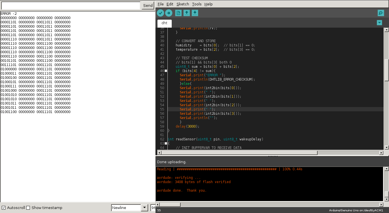
I moved the relevant code from the library into a single file so I could access the data directly and added a function to convert the integer back into a binary string.
uint8_t sum = bits[0] + bits[2];
    if (bits[4] != sum){ // bits[4] contains the checksum
      Serial.print("ERROR ");
      Serial.println(DHTLIB_ERROR_CHECKSUM);
    }else{
      // the int2bin() function converts to a human readable binary string
      Serial.print(int2bin(bits[0]));
      Serial.print(" ");
      Serial.print(int2bin(bits[1]));
      Serial.print(" ");
      Serial.print(int2bin(bits[2]));
      Serial.print(" ");
      Serial.print(int2bin(bits[3]));
      Serial.println("");
    }
    delay(3000);