For the group assignment we tested runout, alignment, speeds, feeds, and toolpaths for our machine. For this I designed a test pattern to be cut, which can be found at machining.dxf.
The group documentation can be found here.
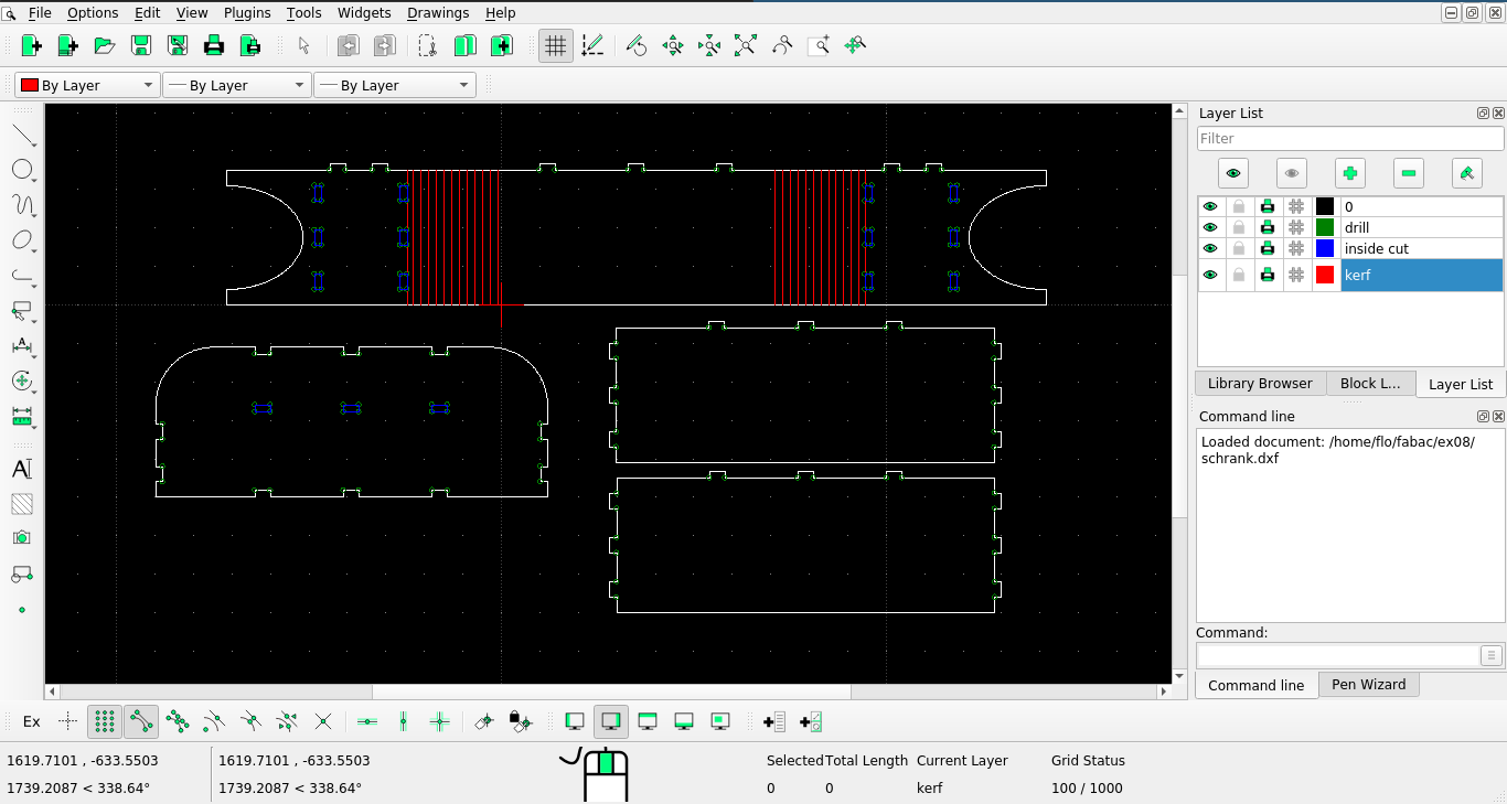
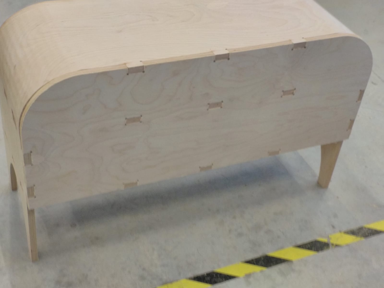
The assignment was to machine something big. I decided to make a small cabinet with kerf bended edges. I designed that using LibreCad and Fusion360. In a first step I drew some initial designs by hand, just as a way of coming up with ideas, not actually trying to create a working design. After having a general concept and some base values for the size of the cabinet I recreated my drawings in LibreCad.
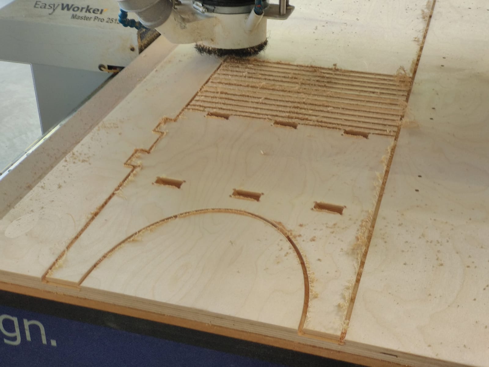
On all corners of inside cuts I placed drill holes, so the round tool can cut the sharp corners needed.
I roughly calculated the kerf cuts using the kerf spacing calculator by blocklayer.com. I went with a curve radius of 150mm and a 90° angle.
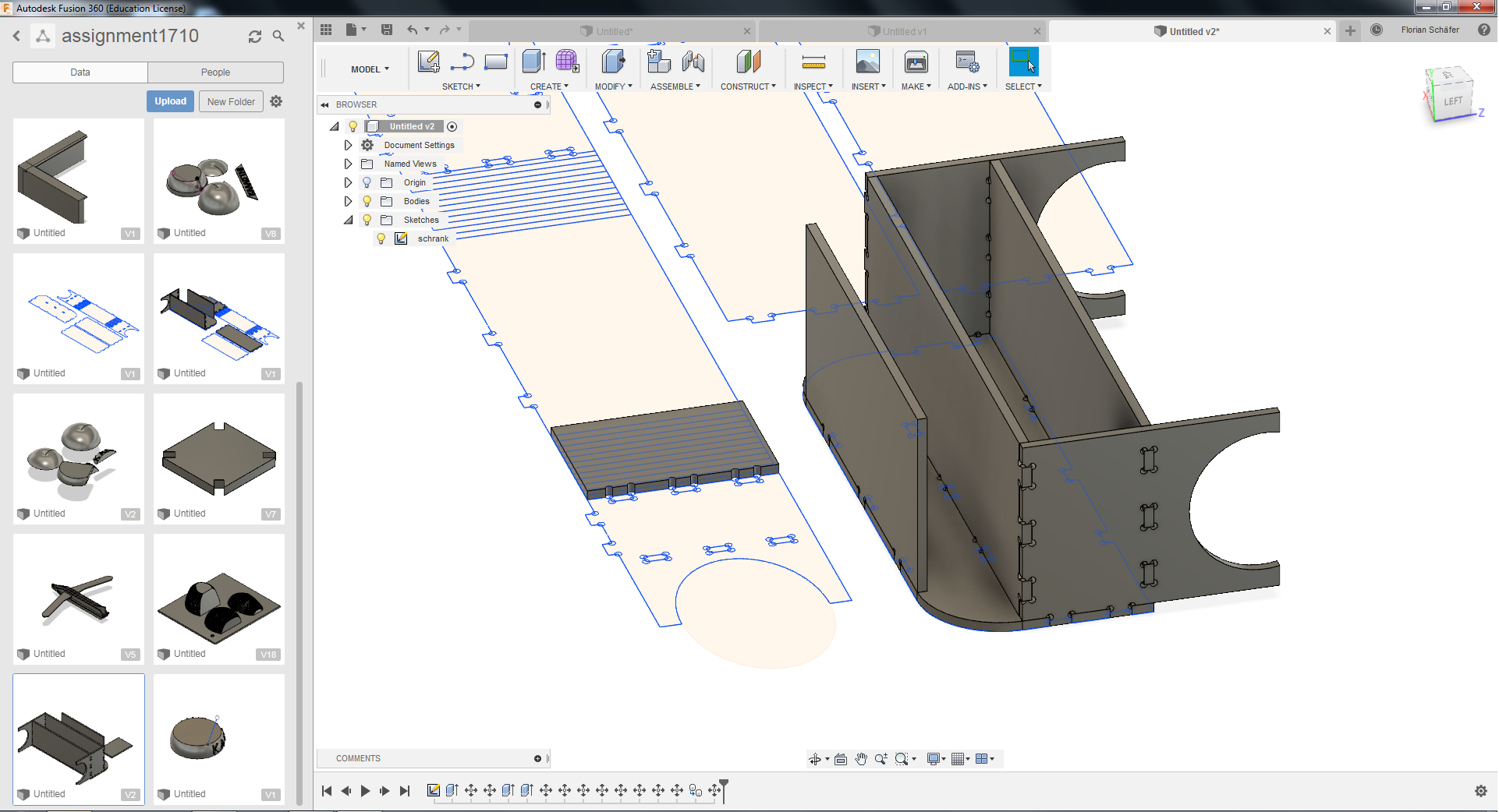
Afterwards I imported the file into Fusion360, extruded all parts by 18mm (the measured thickness of the wood plate I was going to use) and assembled them virtually to see if everything fits. It was very useful to do this, as it allowed me to make a few corrections I wouldn't have noticed otherwise.
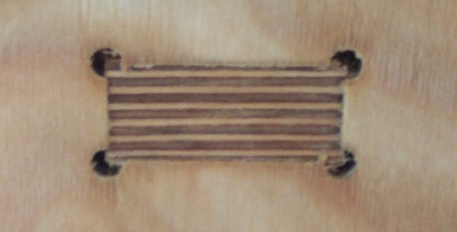
Luckily I did not have to take into account any tolerances in the machining process, as the machine in our FabLab is a professional grade high precision machine. When I tested the kerf by cutting out a small rectangle I measured no difference to my original design, more tests about the precision of the machine can be found in the group assignment. In the following picture a press-fit connection can be seen that was manufactured without taking any kerf into account. It could be hammered in using a soft hammer and made a very tight connection.
When everything was fine regarding assembly I exported the dxf file from LibreCad and opened it in Rhinoceros 3D to check if all lines are closed. I did this by selecting all elements of each layer and joining them using the "Join" tool from the left toolbar. The expectation would be that Rhino tells us it created only closed curves. If that is not the case we can select each part one by one, explode it and then join it again. That way we can find the parts that are not closing up correctly and either fix them by hand or make Rhino close the curve automoatically.
Now I saved the file again, selecting the option "R12 Lines & Arcs" from the save menu.
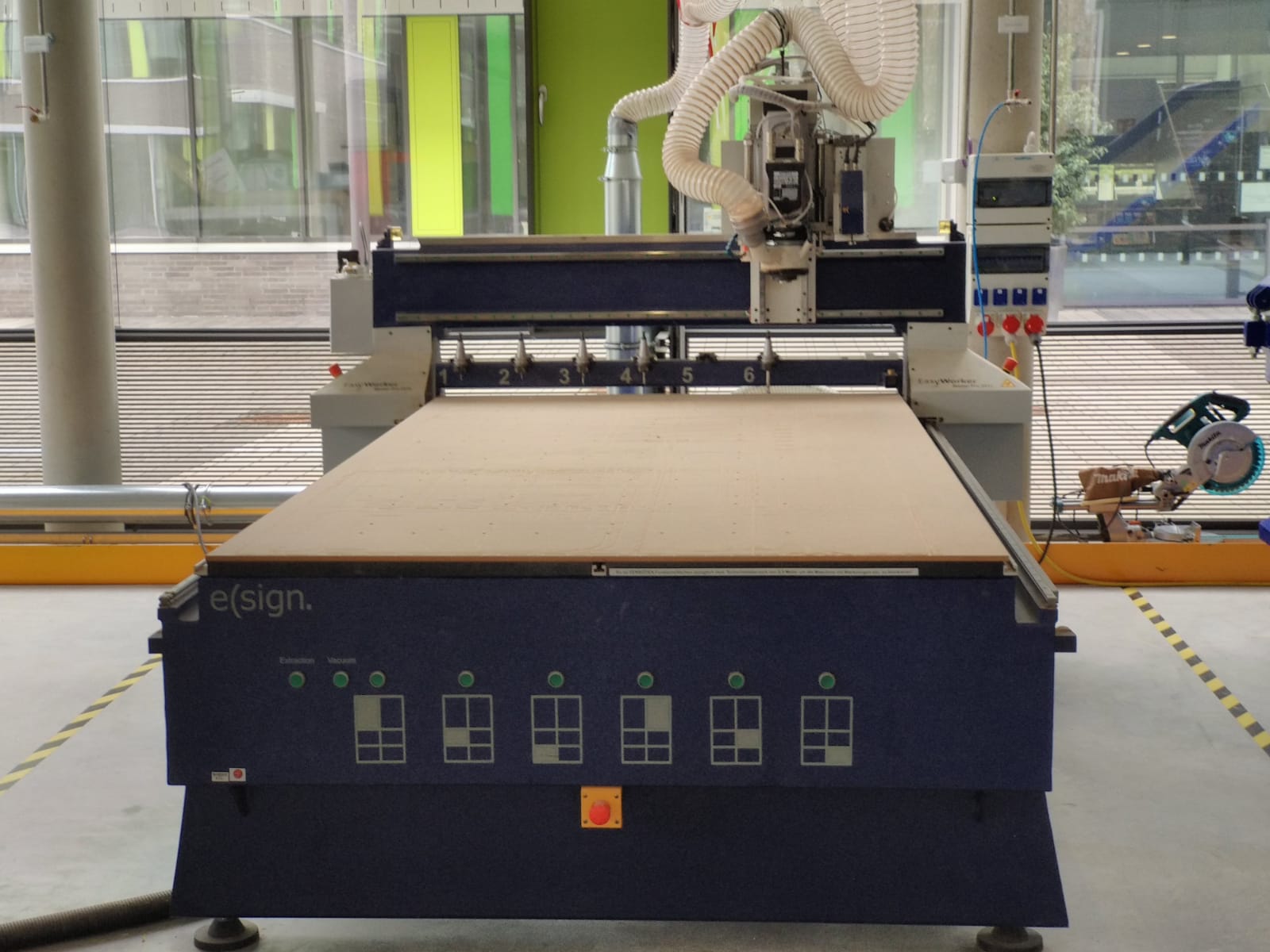
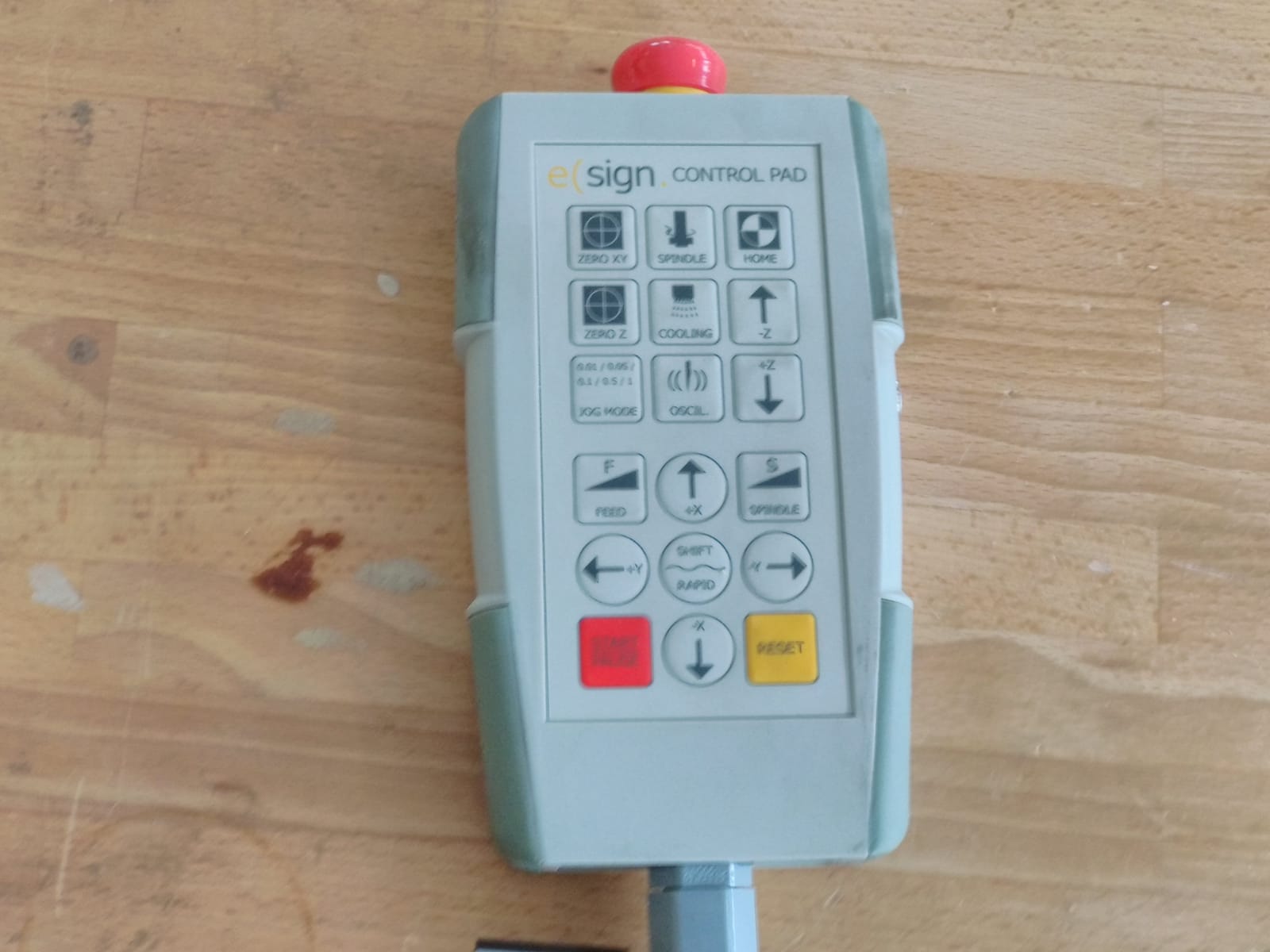
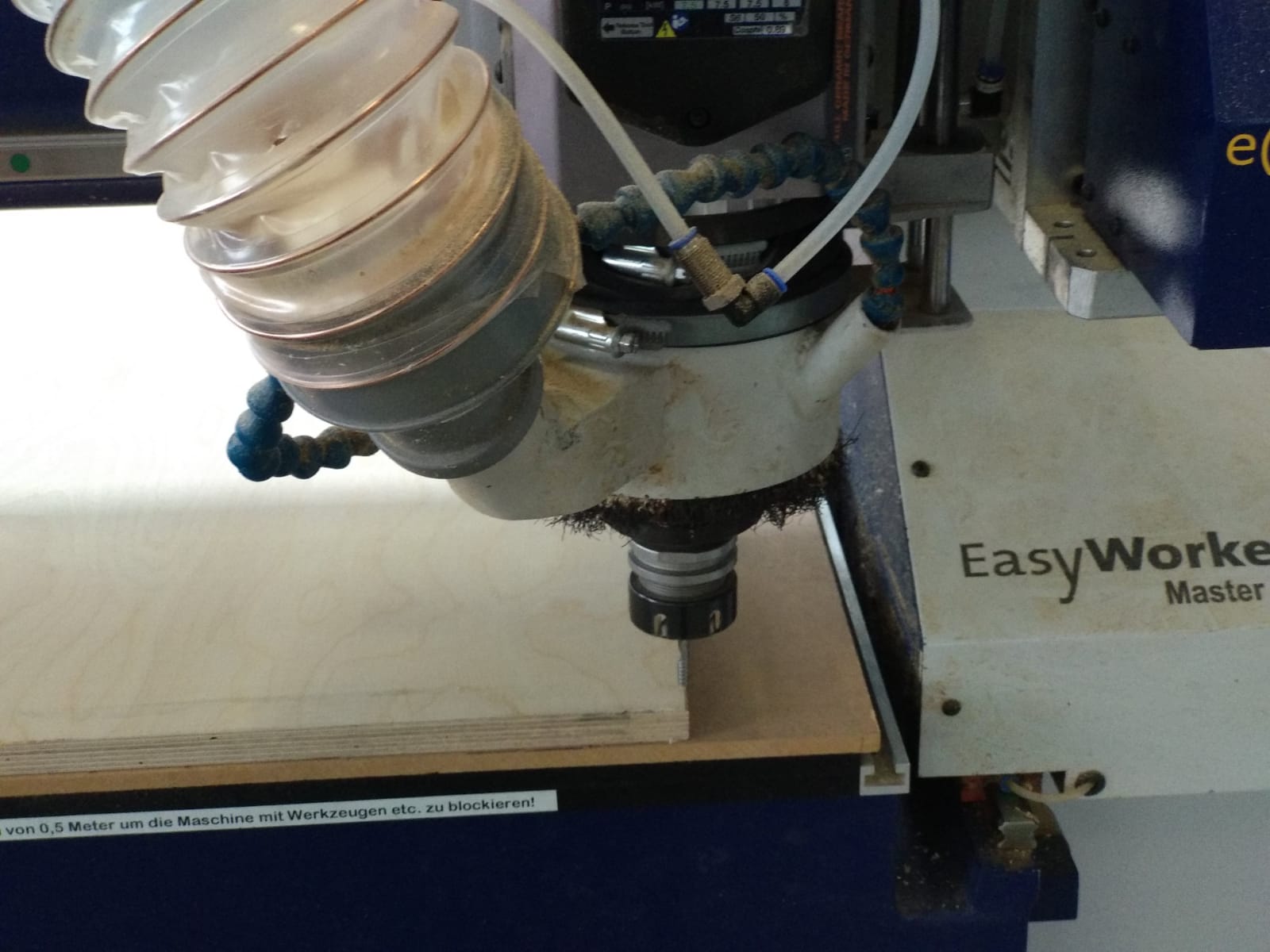
Now the file could be brought to the CNC machine and saved on it's local storage. But before loading it into the CNC software and generating the GCODE we have to initialize the machine. The first step for this is setting the home point. The machine can find it by itself, all that needs to be done is cleaning the machining bed and then pressing the "Home" button on the controller. The machine will slowly move to it's 0/0 point.
Afterwards we will set our work zero point. Note that this is a different point than the one we set in the step before. The correct tool was already picked up by the machine, so this did not have to be changed. We placed the board on the machine and carefully aligned it with the edge of the machining bed. Now the machining head was slowly moved to the lower left corner of the board. If it's movement is not precise enough it can be slowed down using the jog mode key. When the tool was perfectly aligned with the corner I pressed the "Zero X/Y" key.
The Z zero point is set using a sensor that comes with the machine. We placed the tool beside the board and put the sensor below it, directly on the cutting bed. Now we could activate the function of the machine that finds the Z zero point. The tool slowly moves down on to the sensor and stops when it hits it. The tool will quickly move up after hitting the sensor, so do not be in its way when this happens. Now the Z zero point is set.
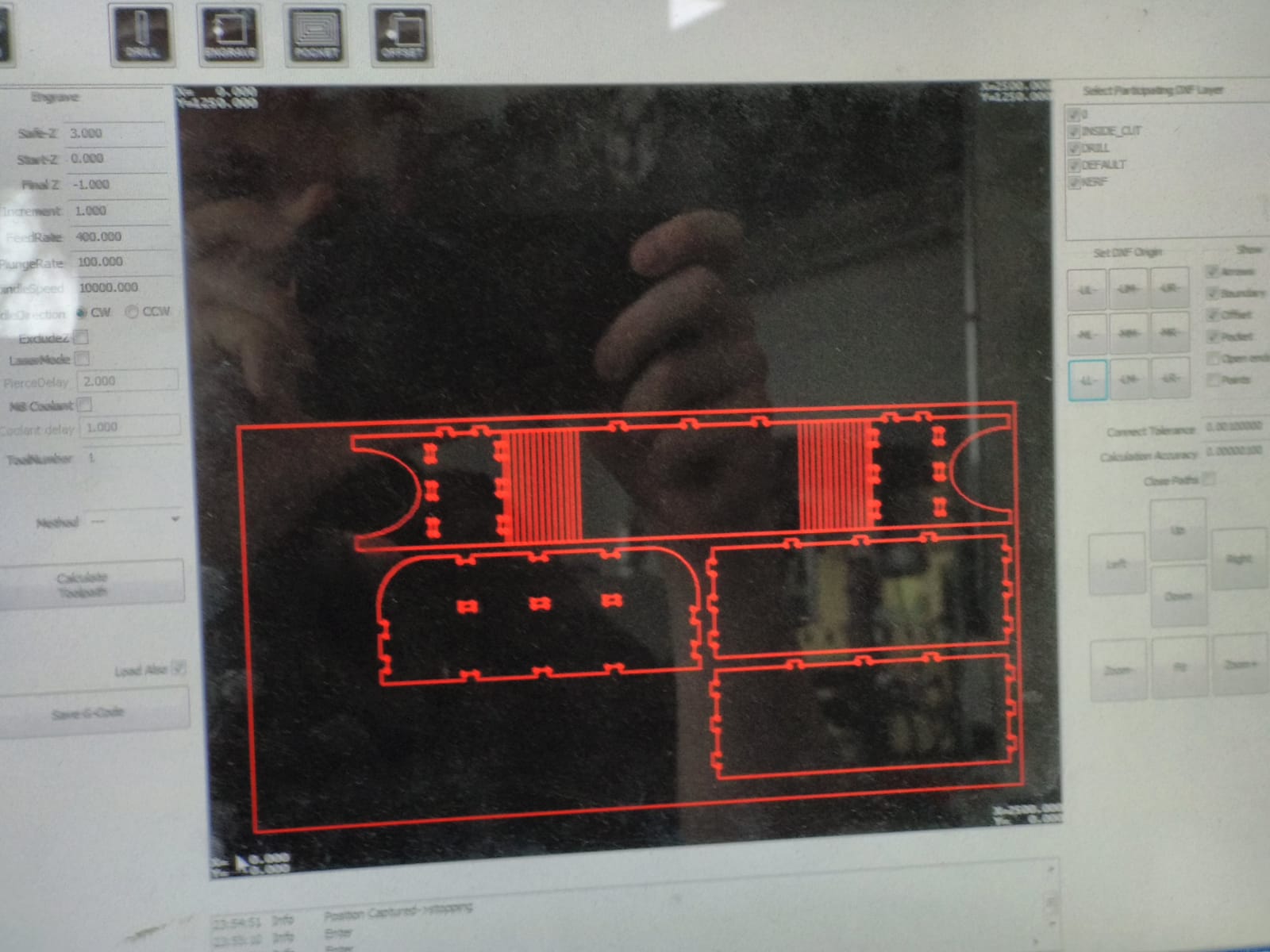
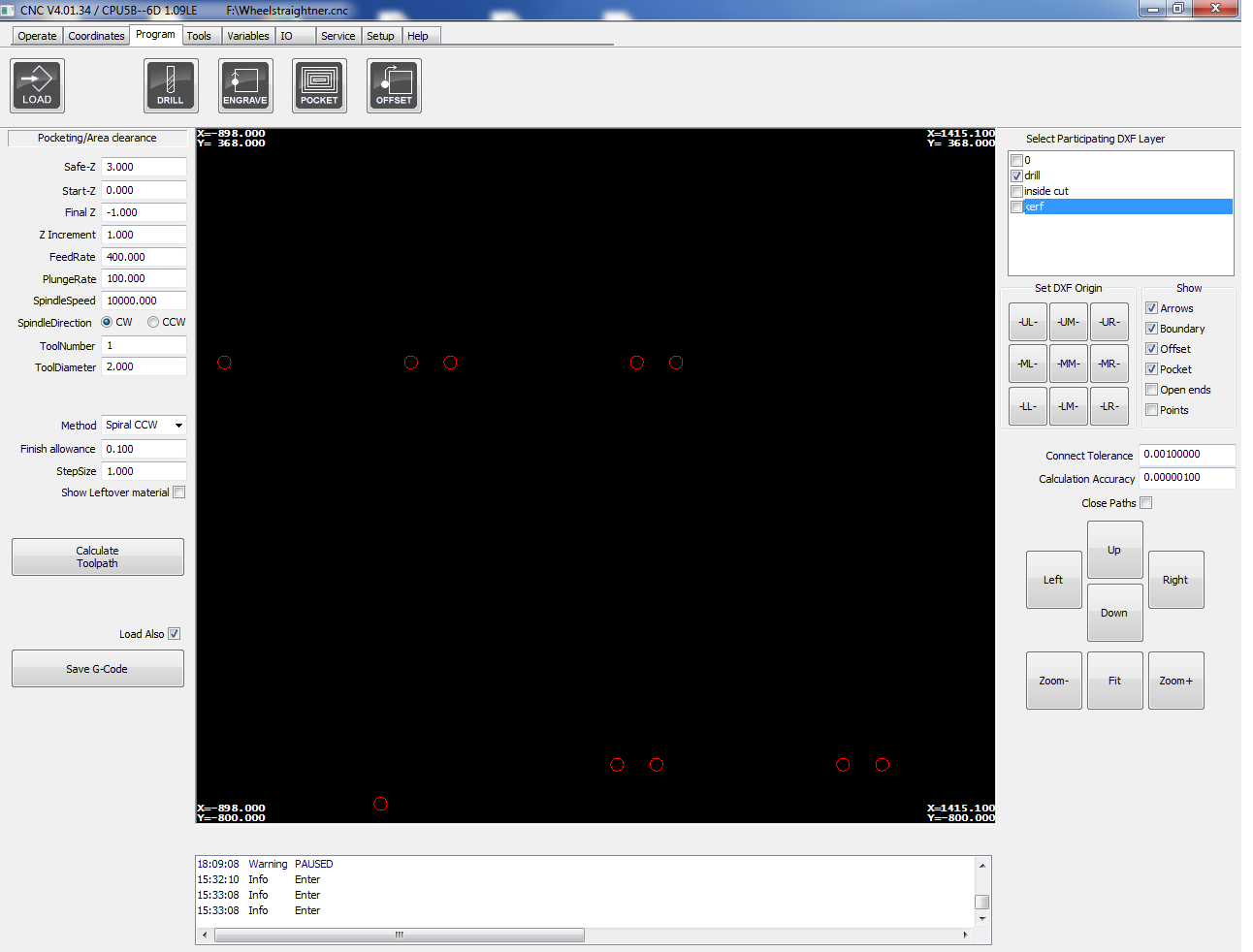
Now the dxf file could be loaded into the CNC program. First it would be placed on the lower left corner using the LL button. Then I turned of all layers but the one for the first job, in this case the drill holes.
The following settings have been used for the different jobs:
For the kerf cuts:
For the other cuts the Final-Z was -0.1 instead, same for the drilling.
After all settings have been made and double checked the GCODE can be generated using the "Generate GCODE" button.
The first job was run in drill mode to drill all the holes that are needed so the connections are fitting.
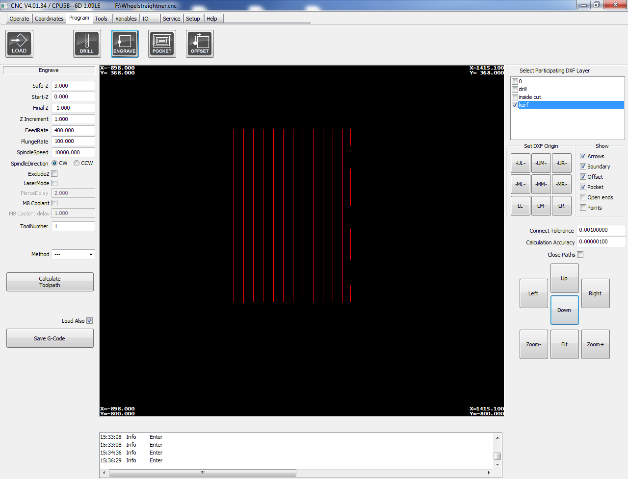
The next job was in engrave mode to create the kerf cuts.
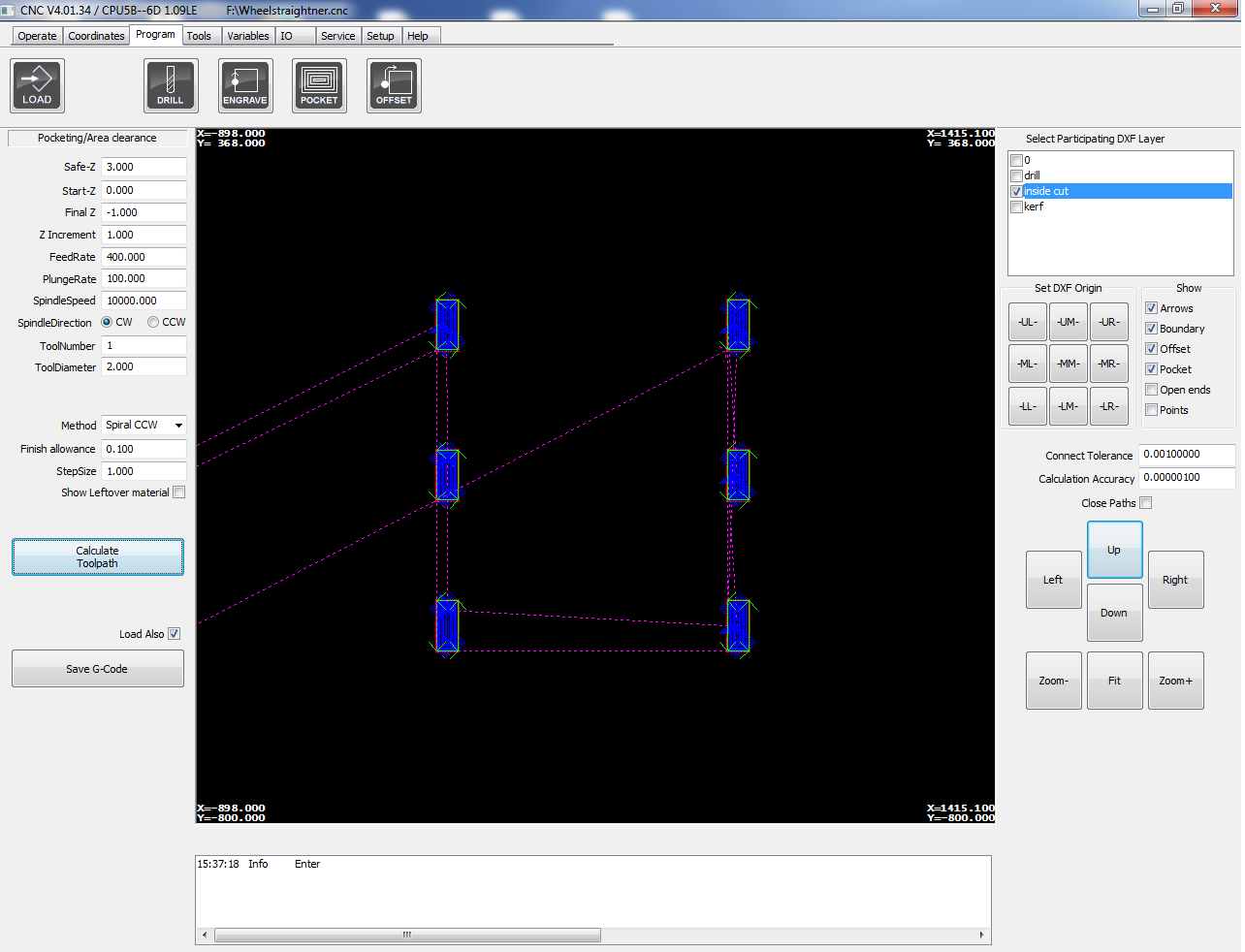
The next one was for the pocket cuts, mainly the holes for the press-fit connections.
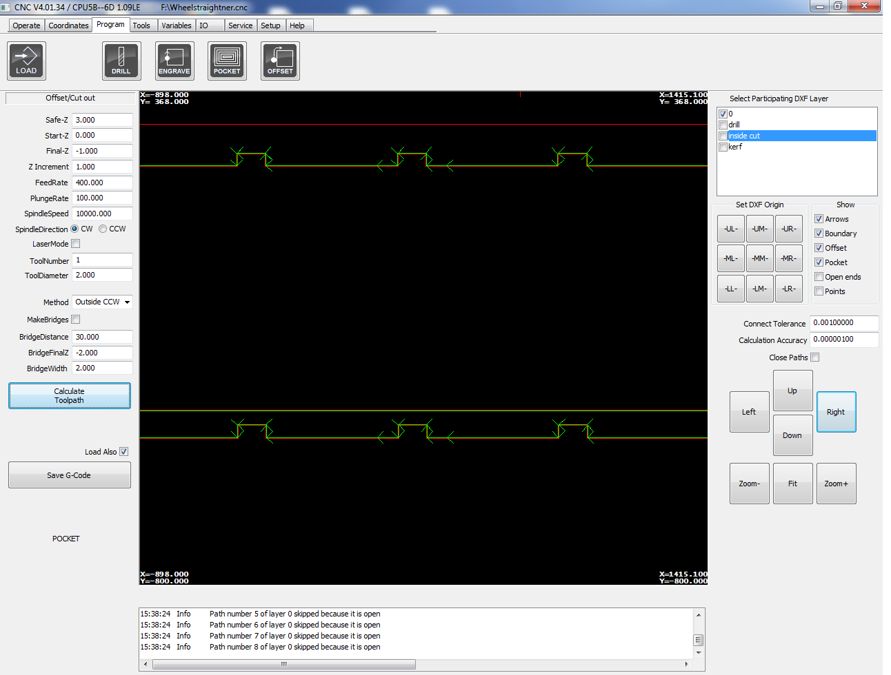
The last job was in offset mode, cutting everything out. This one was the largest one, as the machine has to follow the full outline of the design.
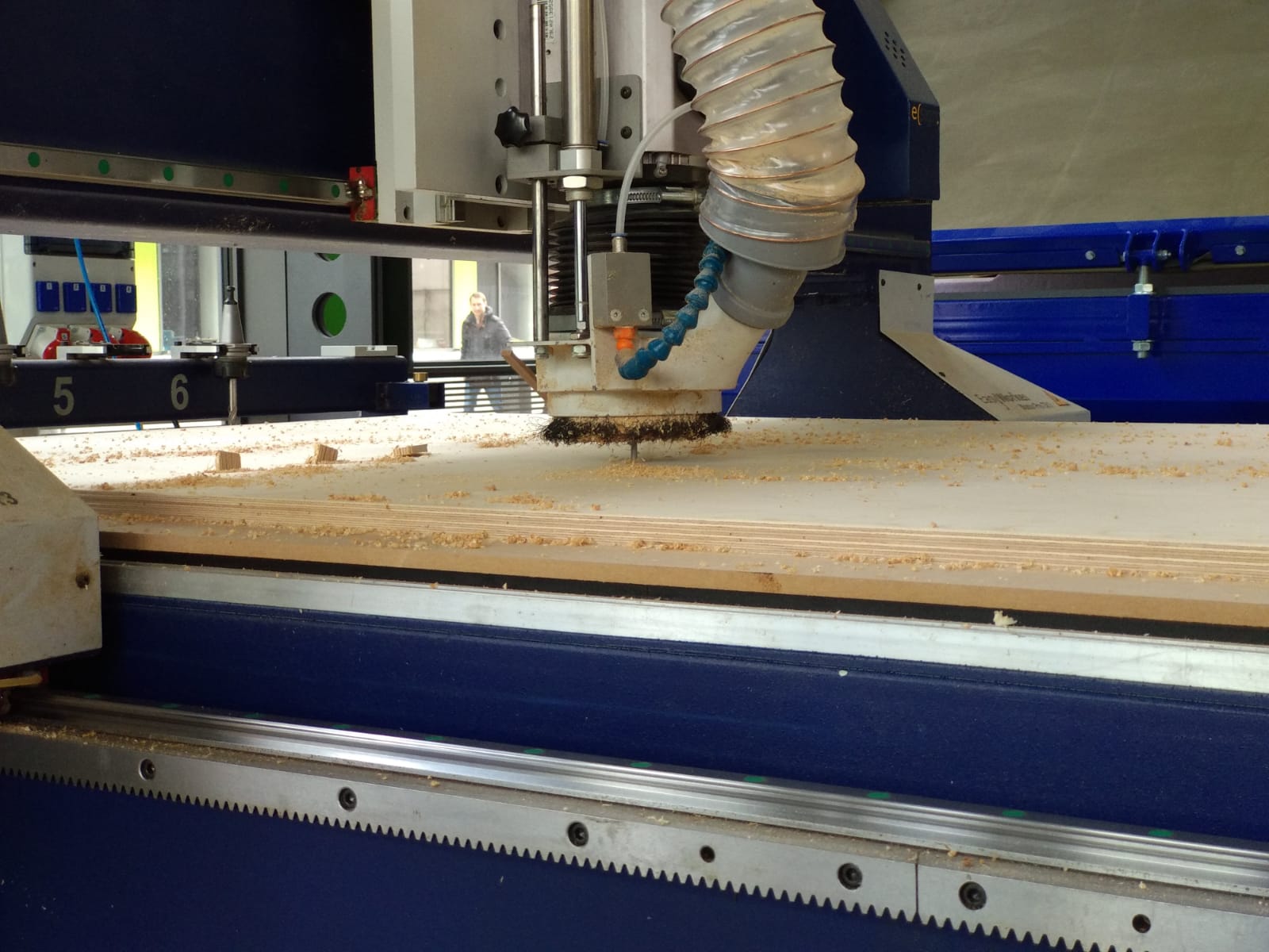
Each job is started by pressing "Start". Beforehand the vacuum of the machine has to be turned on, as well as the dust filter be acitvated and the dust cover moved down. Only then a job can be started without damaging the machine or messing up the material.
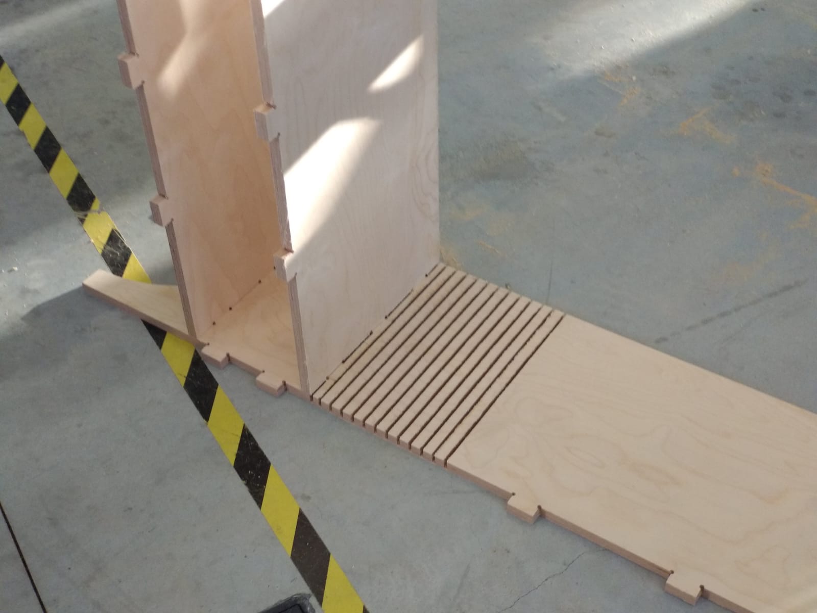
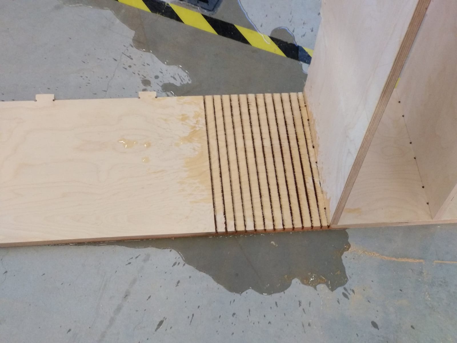
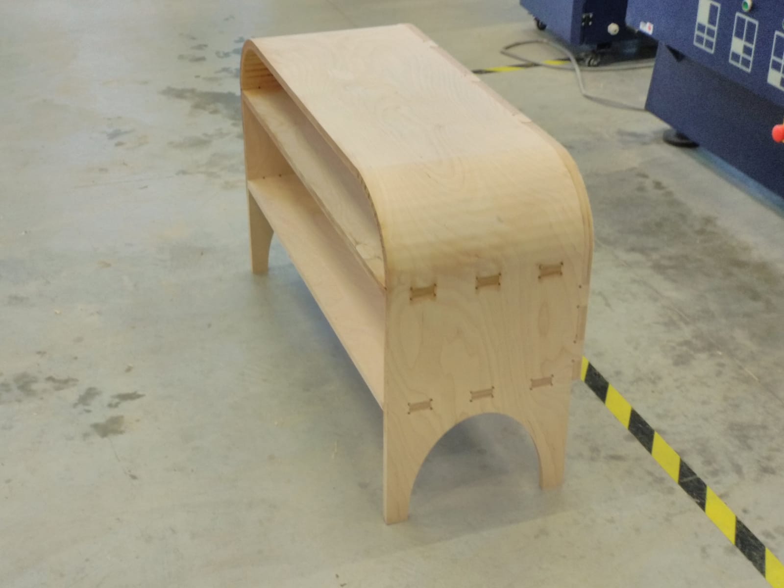
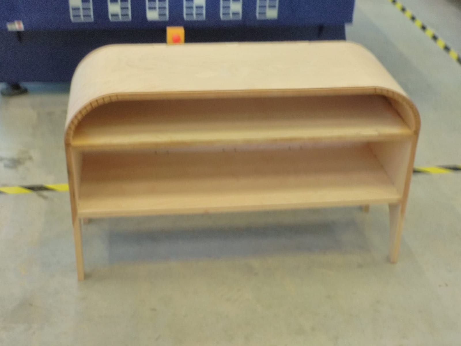
We assembled all the parts using a hammer. It took quite a while to do that, but in the end all parts fitted together tightly. The bended parts where covered with hot water to give the wood a little more elasticity and reduce stress during assembly.
I used linseed oil as a finish. I coated the wood three times, waiting 24 hours between each coating. Linseed oil can self-ignite under certain conditions, so always remember to clean the brush or sponge you have used with water. After the coating the surface is still oily, so sensitive things like books or clothes should not be placed on it for another week or two. (The book I was reading at that time now has 5 oily transparent pages)
⬅ Back to overview