Fusion360 can be used for both 3D and 2D design. It has a clean interface, a broad range of features targeted towards technical requirements and can be downloaded for free. The downsides are that it is a proprietary software which even requires registration and logging in before use. Designs are saved on the Autodesk servers and not on the local device if they are not explicitly exported.
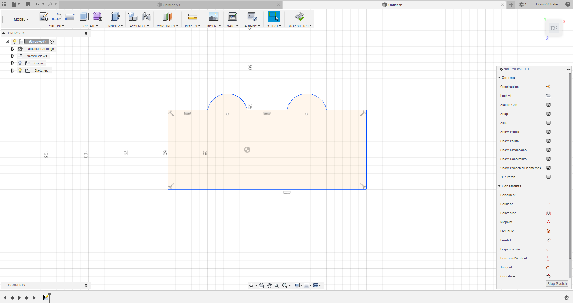
To create a 2D design I created a new "Sketch" from the "Sketch" menu and selected the plane in 3D space where the 2D drawing should be placed. Now all 2D tools can be used to create a design. If it's finished we can leave the mode using the "Stop Sketch" button. If we decide to change something later we can double-click the sketch in the tree-view and reenter 2D mode.
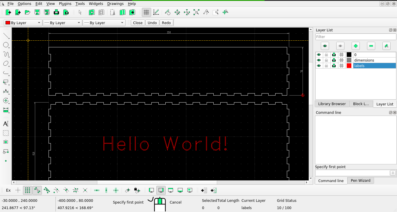
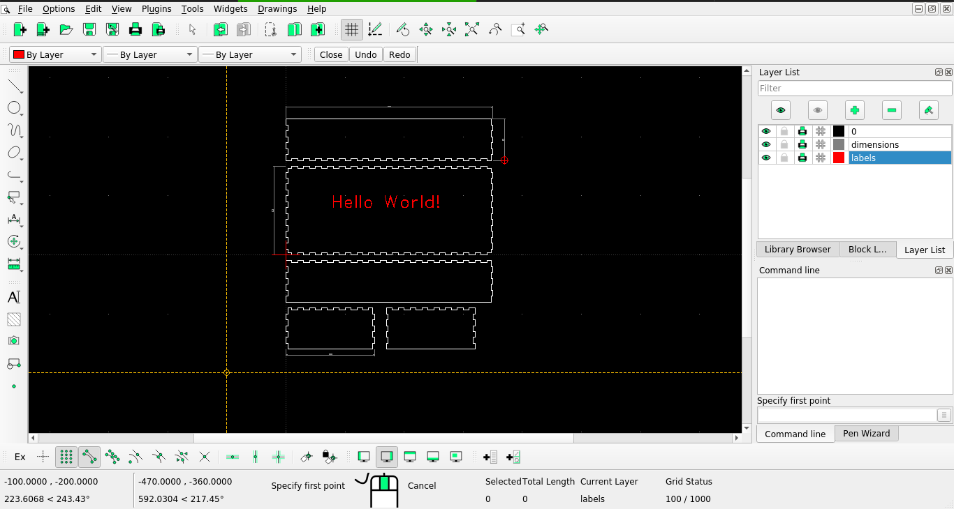
LibreCAD is a FOSS 2D CAD tool which runs on all common operating systems. It does not require any kind of registration, I could simply clone it from GitHub and build it from source. It's interface is not as polished as the one of Fusion360, but in my opinion it's also less confusing. To test it out I created a simple open box that could be laser cut. The grey layer is just marking the dimensions and would not be cut, the red layer is for engraving.
A useful hint when using LibreCAD is to use the context menu, which will show the tools that have been recently used. This is an essential part of the LibreCAD workflow and without it the handling will feel very slow and tedious.
I decided to first try OpenSCAD for this exercise, as I had never used it before and have made bad experiences with other FOSS 3D modeling software. I installed OpenSCAD version 2019.2.7 from my distributions package sources. The object I made is a case for a light, that can be mounted on the backside of a PC monitor to extend the picture shown on the screen with ambient colors.
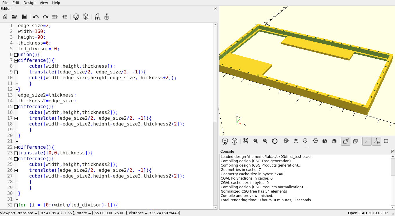
I started of with calling the cube() function with a width an x value of 160 and y of 90, as well as a z value 6 for the thickness. Later I moved those values to variables so I could actually profit from the advantages of parametric modeling. From that cube I moved on to call the function again with slighty smaller values and a small offset I created using the translate() function. Now those two cubes could be combined using the difference() function, thus creating a hollow frame.
The other flat parts where added in a similar way, by creating cubes and translating them to the right place.
The last thing I needed where holes for the LEDs all arround the frame. Instead of placing every hole by hand I used for loops. For the horizontal rows this looks like this:
for (i = [0:(width/led_divisor)-1]){
    translate([(i*10)+led_divisor/2, edge_size2/4, thickness-thickness2]){
        cylinder(r=1, h=edge_size*2+2);
     }

     translate([(i*10)+led_divisor/2, height-edge_size2/4, thickness-thickness2]){
        cylinder(r=1, h=edge_size*2+2);
     }
}
The led_divisor value decides what spacing is left between the holes.
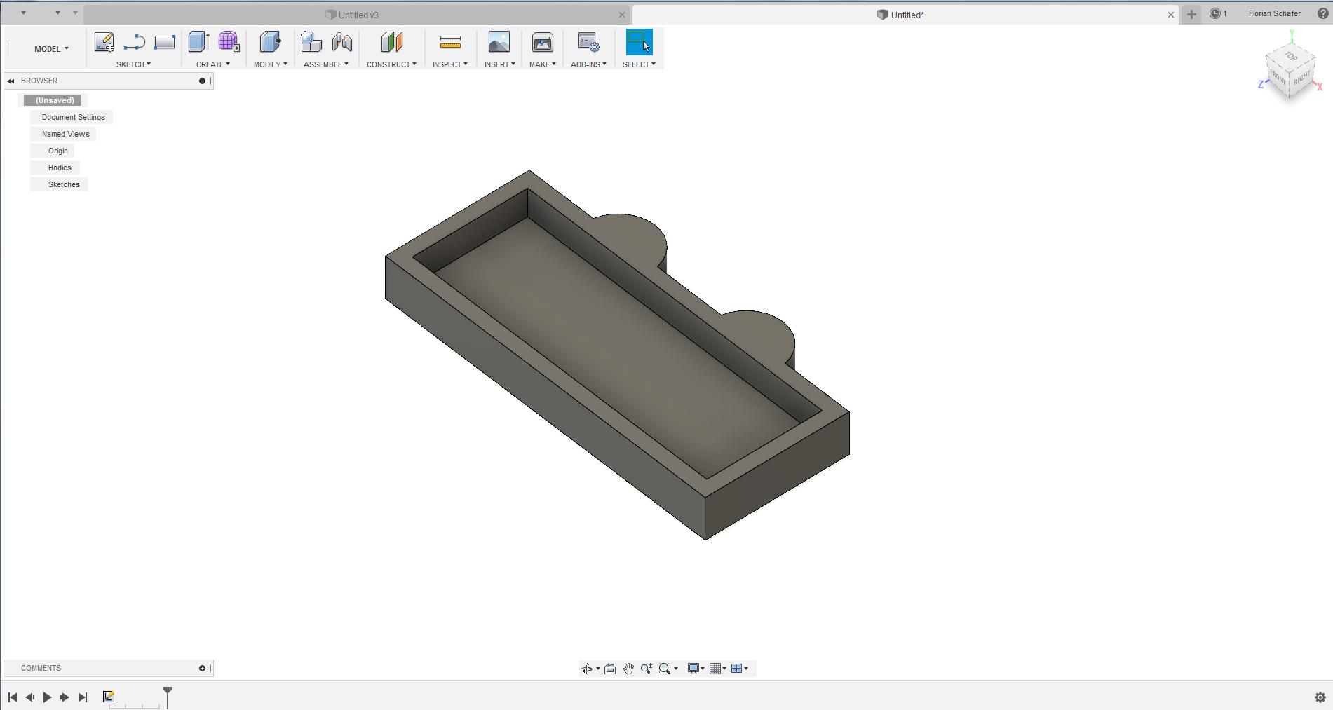
Fusions 3D options are a lot more accessible than the ones of OpenSCAD, but it also has the aforementioned downsides. 3D models can be created in a variety of modes, for me the "Model" mode was the most commonly used. Primitive bodies can be created using the "Create" menu and be combined and modified afterwards to form more complex components. I decided to use the 2D design I created before and extrude it into a 3D model. For this I selected "Extrude" from the "Create" menu and pulled the faces of the sketch object upwards.
Another software I have used before is the commercial modeling software Cinema4D. It is geared more towards visual design tasks and not towards creating physical parts for precise production methods. However it could be used for creating more artistic things, for example using a 3D printer. It also has excellent capabilities for rendering, but these can't really be applied in a digital fabrication context.
⬅ Back to overview