.png)
Hi! Welcome to Week 7
This week’s assignment was to redraw the echo hello-world board, add (at least) a button and LED (with current-limiting resistor) check the design rules, make it, and test it extra credit: simulate its operation.
This week’s assignment was to redraw the echo hello-world board, add (at least) a button and LED (with current-limiting resistor) check the design rules, make it, and test it extra credit: simulate its operation.
We started with a walkthrough by our instructor Nadine Tuhaimer, where we discussed the components and parts that go in an electronic board. We then opened Eagle and learned how to build the schematic by adding different components and linking them, before opening the board section and starting the routing process, which is to arrange the components and paths in an optimum way.
Now that we were done. I headed back to Eagle and downloaded it on my laptop, along with the Fab Library in order to use the components assigned. I added it then by copying and pasting it in the Eagle folder on my laptop.
Now I opened Eagle, for the schematic part, these are the orders that I used:
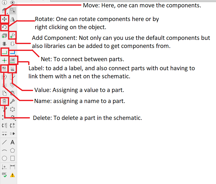
Then, I started adding the components and assigning labels to different diagrams and linking them:
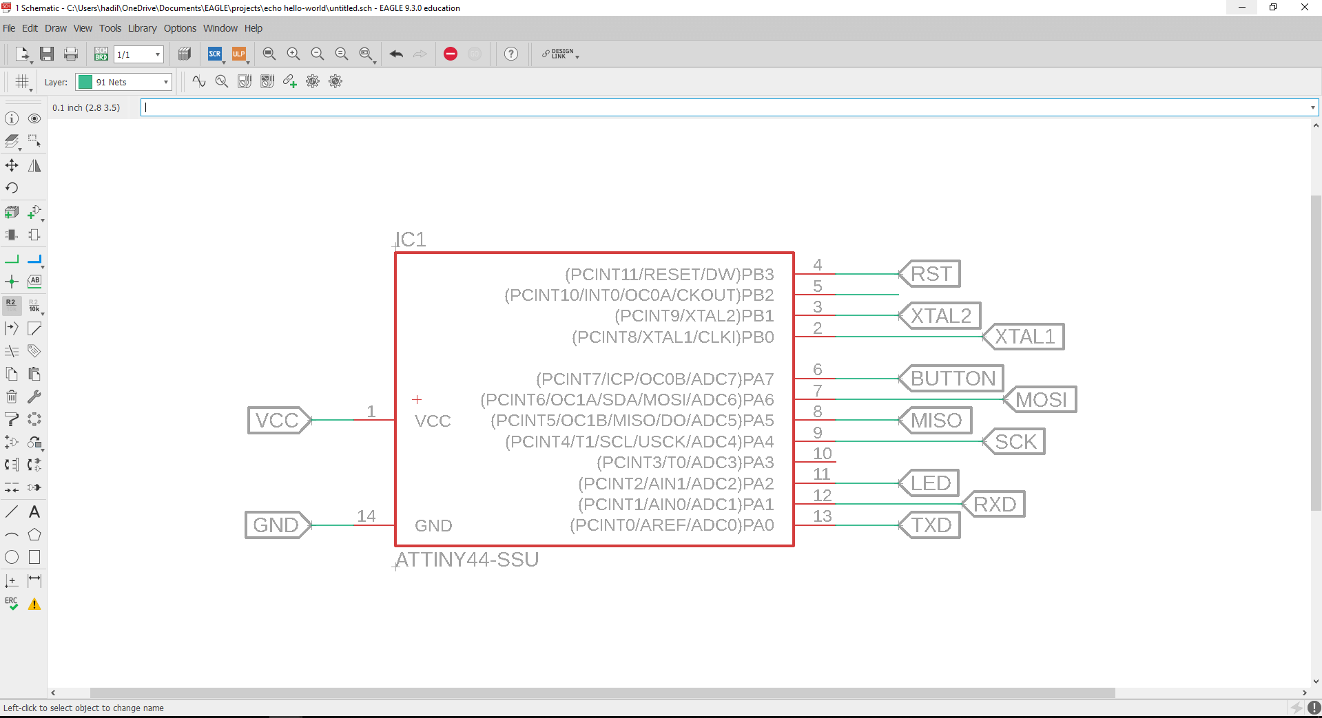
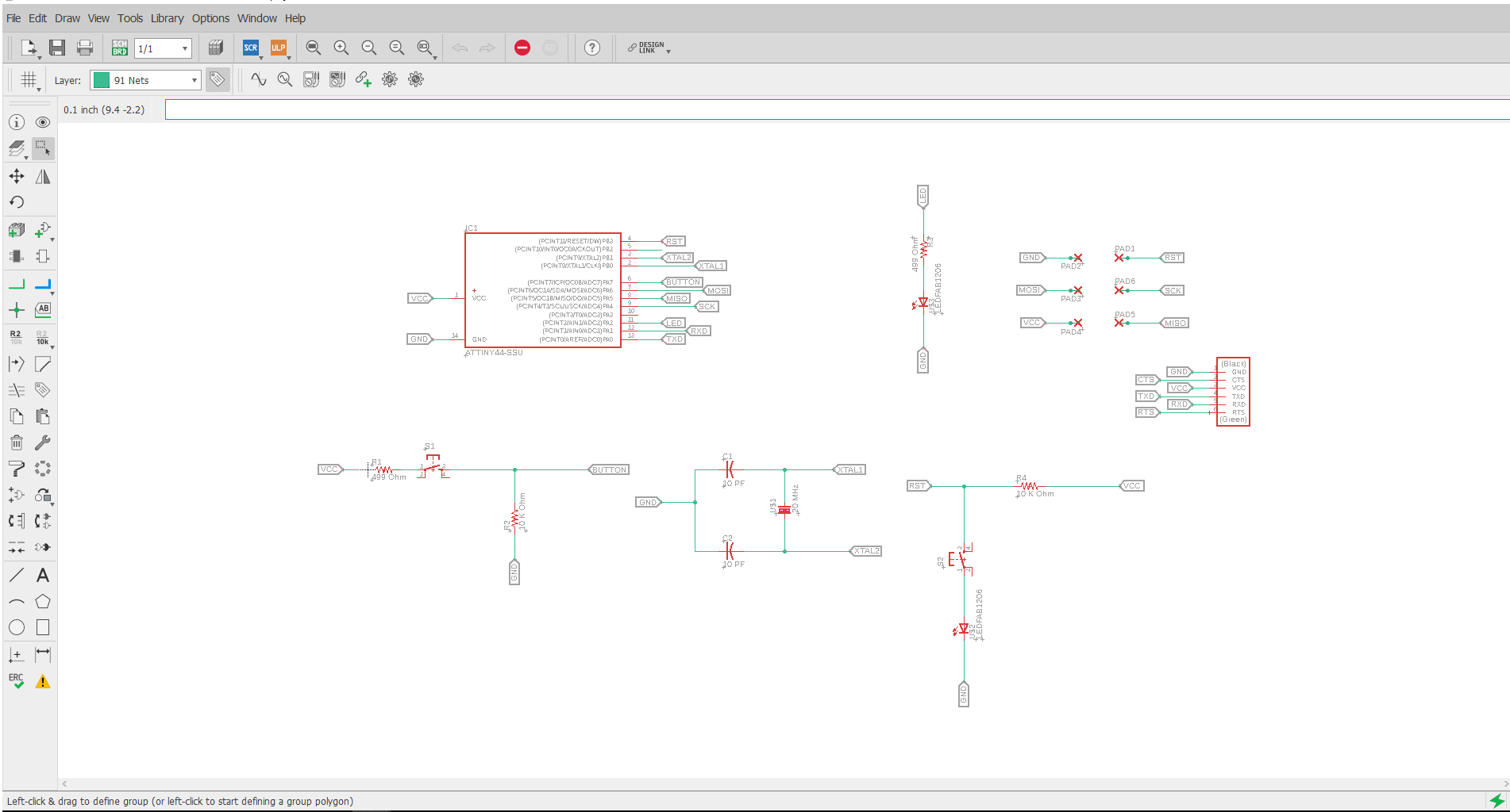
This part was quite simple as it was only placing parts and connecting, and here’s the finished schematic, you can note that the part to the lower right is the button and light I added, I connected them to the reset, gnd and VCC pins.
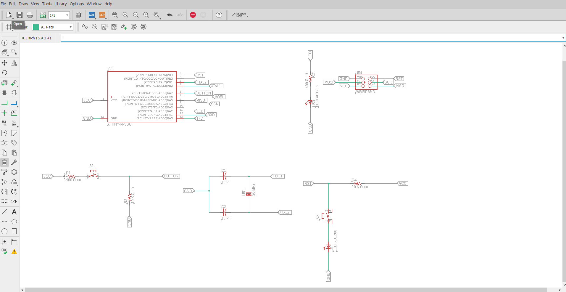
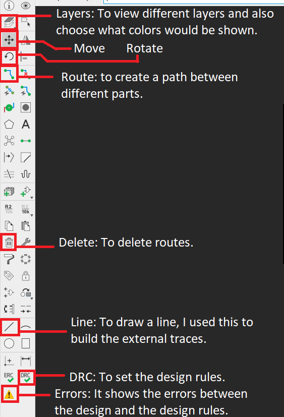
Now, it was time for routing. When I clicked on this icon![]() it opened a new window that contained the components and links from the schematic. Where everything is crowded in one place. Here are the orders that I used in this part:
it opened a new window that contained the components and links from the schematic. Where everything is crowded in one place. Here are the orders that I used in this part:
I tried to find a way for them to fit in a small area for some time, but then I remembered a trick our instructor Nadine taught us, which is to separate the head pins to single pins and place each one where we would like to, so I went back to the schematic and deleted the pinhead 2x3 and added 6 1x1 pins, and linked them to the ATtiny by naming them with the names assigned previously to the ATtiny. O also added the FTDI to the schematic.
Then, I headed back to board and started arranging them again until I was satisfied with the results.
I went and added the Fab Design Rules, and checked my board, where I got one problem with the clearance:
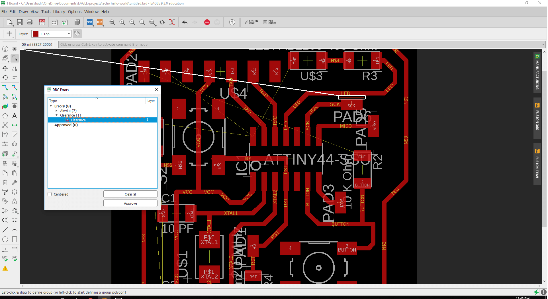
This was easily edited by moving the parts around. Now the only errors showing were for the ground connections.
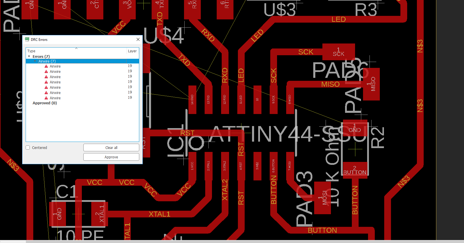
And these were edited by dawing a boarder using the polygon and setting the signal to be GND and then clicking on Ratsnest.
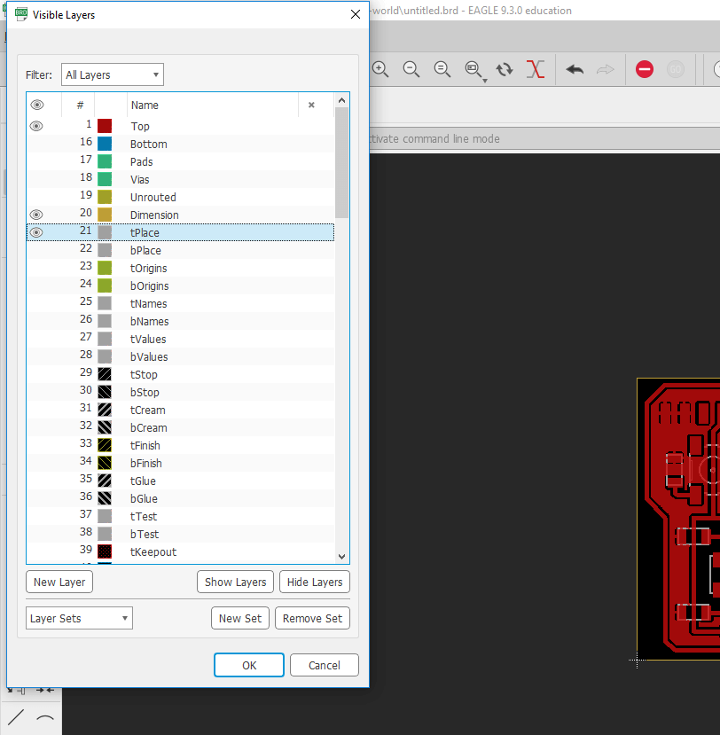
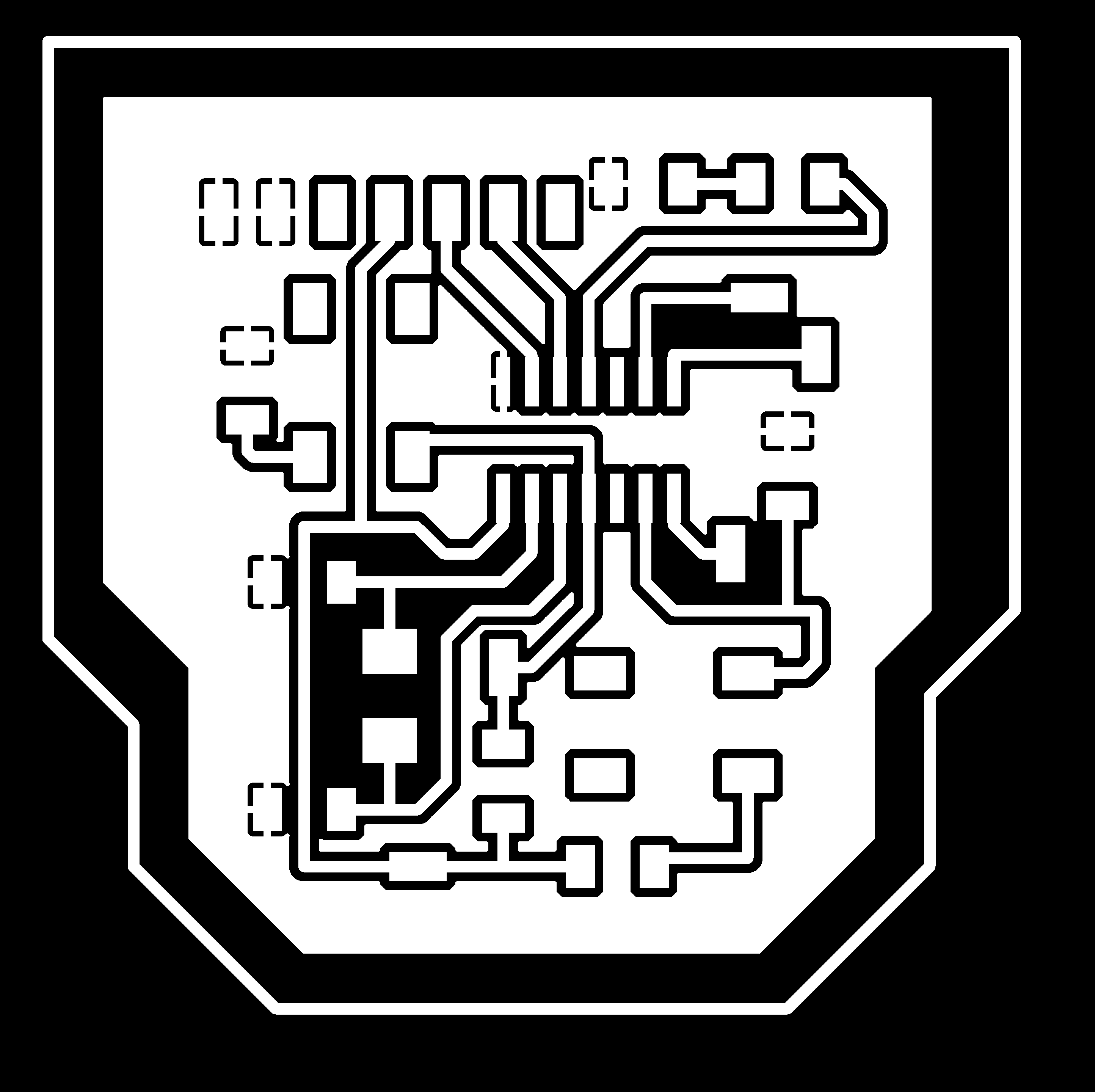
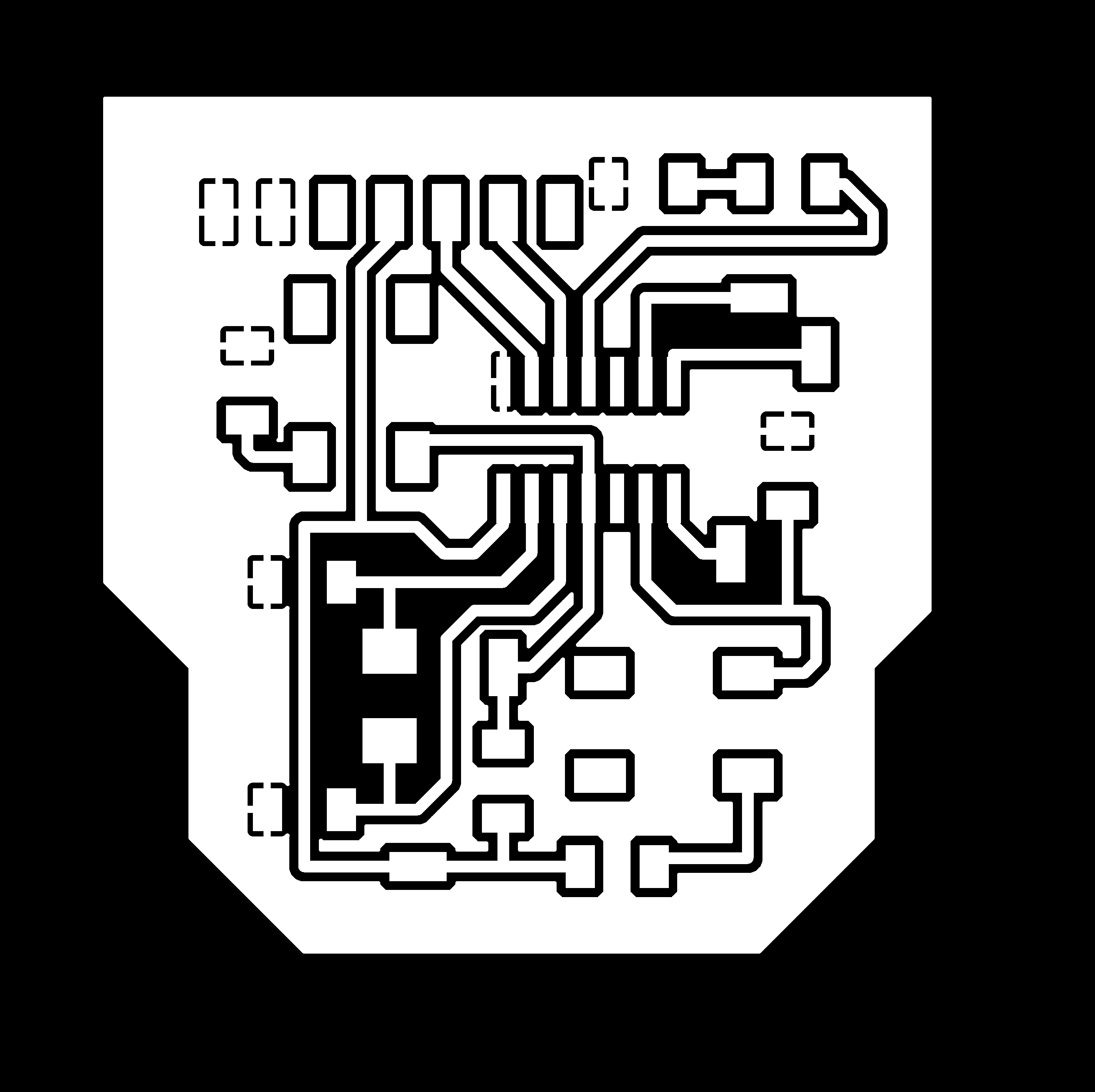
Then from layers, I hid all the colors in layers (except for the red one) as these two where the one containing traces in order to prepare for exporting. I hid the colors by clicking on the eye icon next to each one.
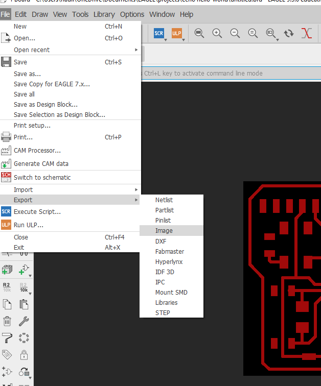
I then exported the file as an image, and from the window I chose the size to be full and to have monochrome, with a resolution of 1500 dpi and you can download the board from here and the schematics from here, and with that, I was done with EAGLE!
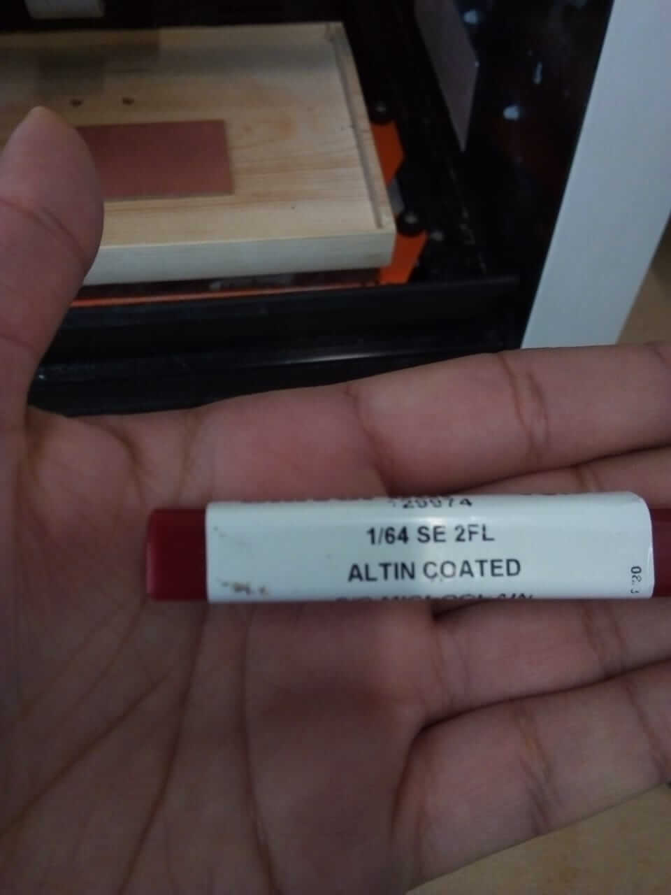
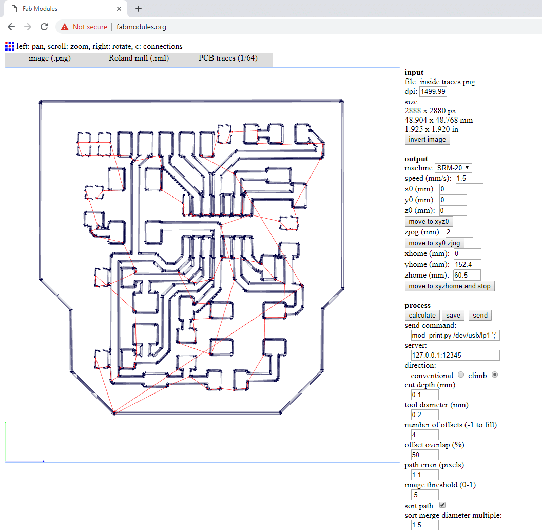
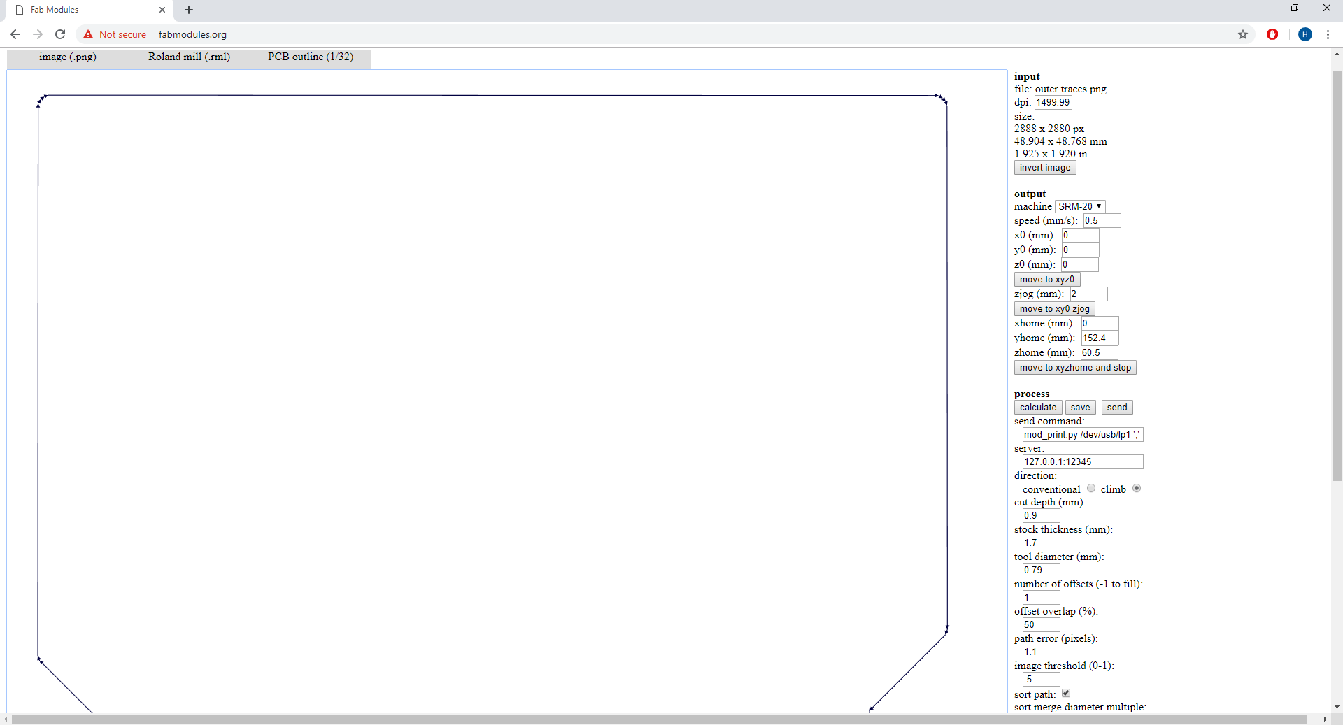
Next, it was time to make the board. I opened the traces image I saved earlier on paint, and made 2 copies of it, where in the first one I kept the inner traces and on the other on I deleted them and only kept the outer trace. I then headed to Fab Modules and prepared the files for the VPanel. First, I did the inner traces where I used the following settings and cutting head:
I chose the file type as image, and the machine, and traces on the top left of the page, as for the settings, on the inputs section I added the dpi as 1500 to maintain the size of the image I downloaded from eagle. On the output settings I added the machine I'm using, and the speed is 1.5 for the traces, x0, y0, and z0 are all zeros because I want the milling process to starts at the origin. Zjog is the distance I want the cutting head to go upwards before it moves from one point to another when it's not milling, I chose 2mm, as for the number of offsets I chose 4, note that the more offsets you have the more you're sure that no traces are touching each others, but the longer the milling process will take.
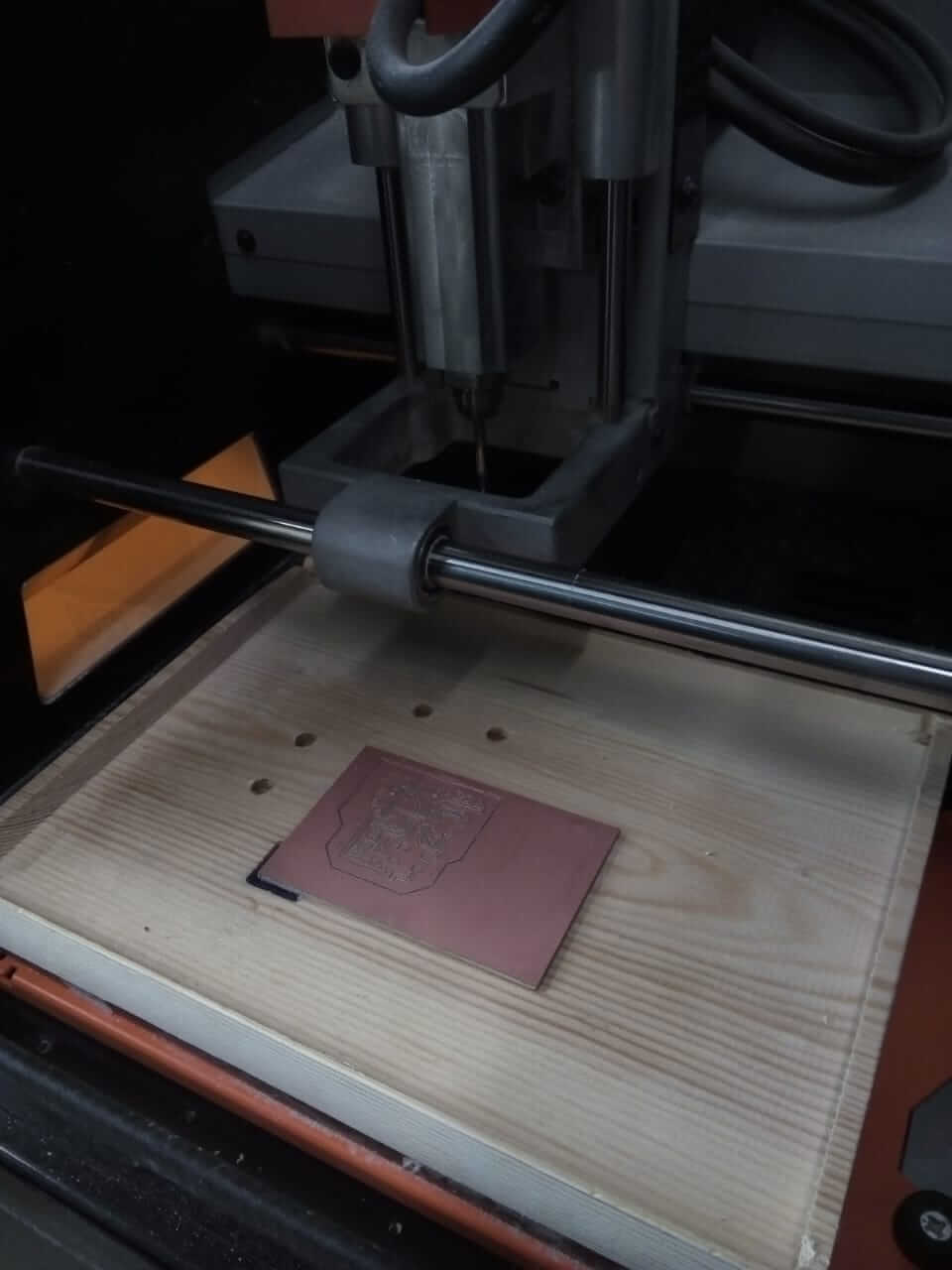
I then fixed my board on the bed of the SRM-20 using double face tape, calibrated the XYZ coordinates, and started the engraving process! Fortunately, milling my board went smoothly and the way that I wanted it to be, no traces were left or erased, the smoothness wasn’t bad (although it could’ve been better but the cutting head wasn’t the best one to use).
Now for the outer traces, I head back to fab modules and uploaded the picture of the outer trace and changed the settings and the cutting head to fit the required output as follows: (note that I changed the settings on the top left from traces to outline, I lowered the speed to 0.5, and raised the cutting depth to 0.9, and changed the tool diameter)
After running the machine, I got this result that I wish we can just look at it and admire how good that powder looks :D
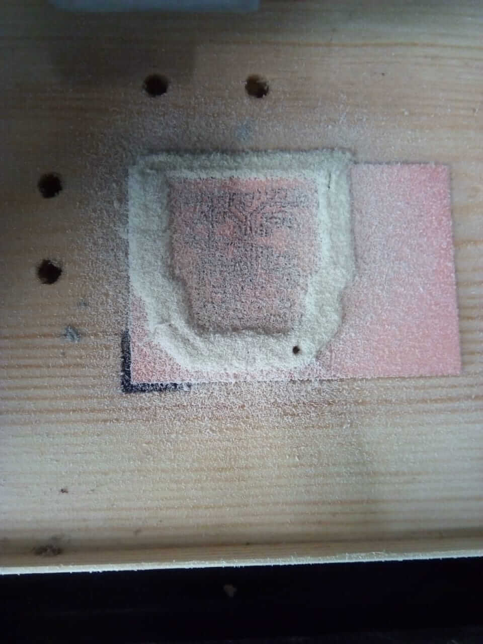
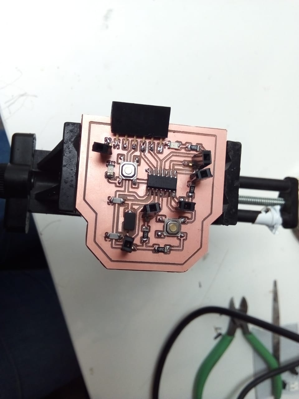
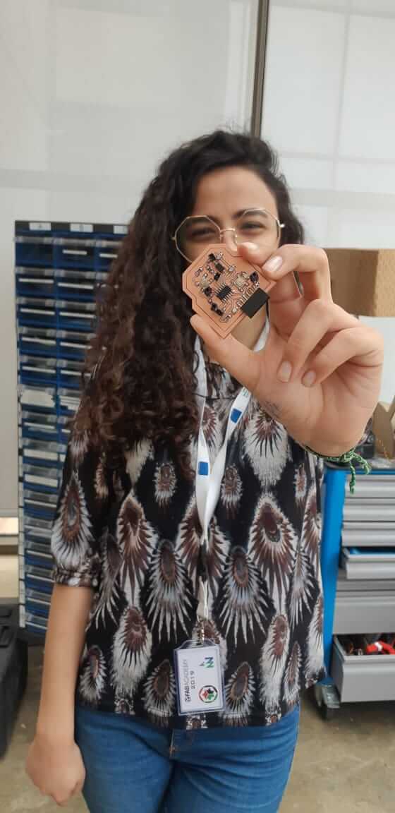
After cleaning up the board and taking it out, this is how it looked:
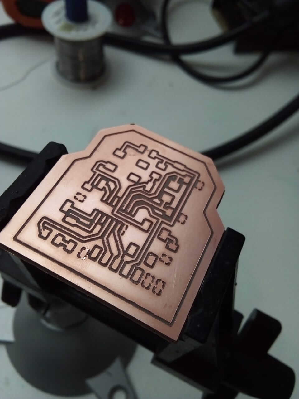
and now, I had to start the soldering process. I prepared the parts that I already added in the schematics. And started the soldering process by adding the components based on the board I designed on Eagle:
1 ATtiny44 microcontroller
2 Resistors 499 ohm
6 individual header pins
1 FTDI
1 Crystal 20MHz
2 Capacitors 10pf
2 Switches
2 LEDs
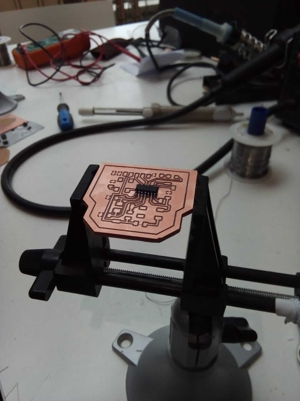
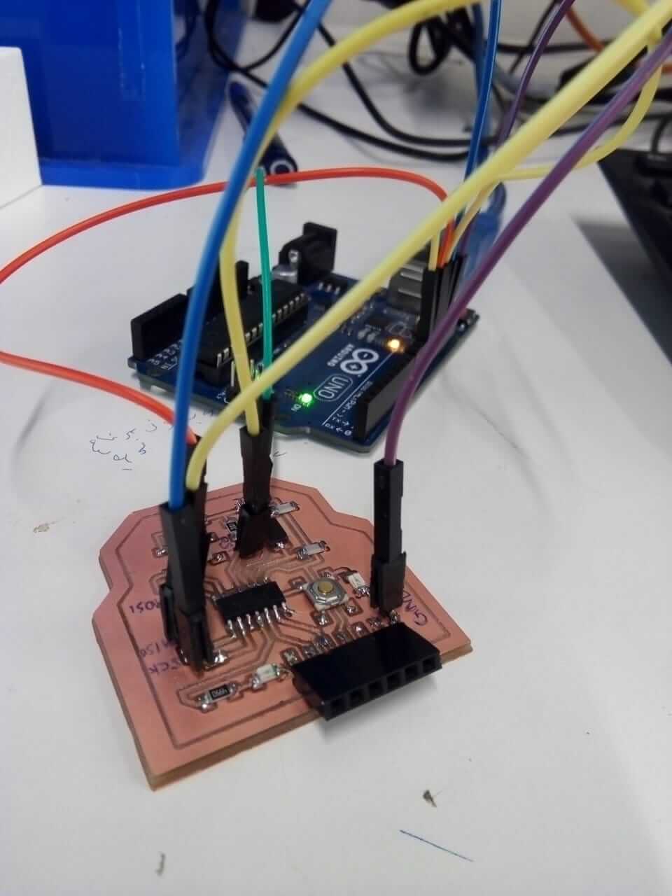
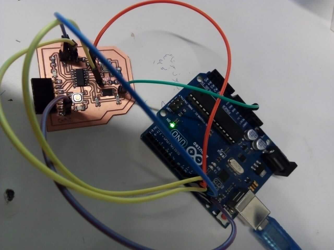
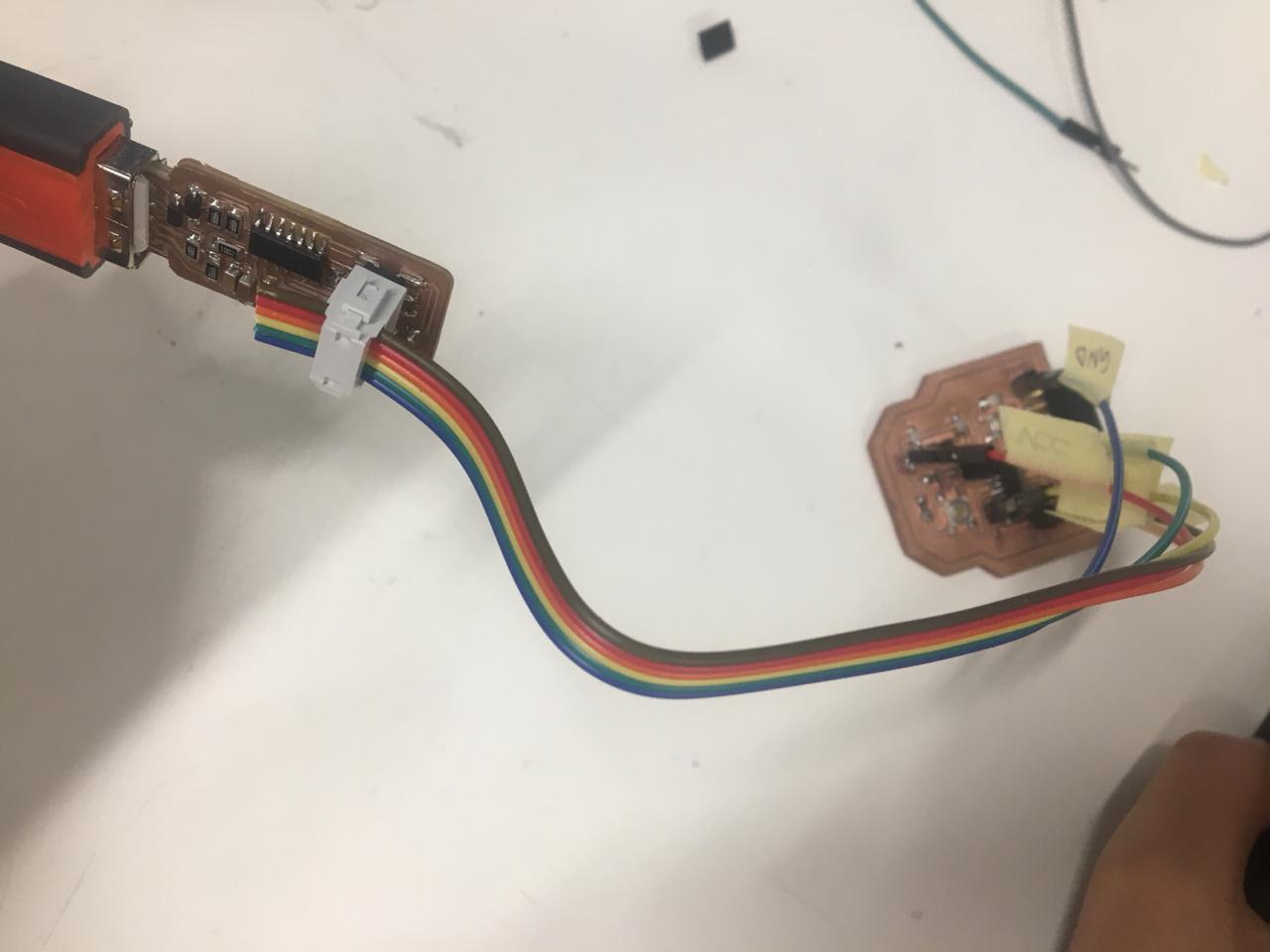
And with a soldered components on my board, I was ready for programming :D I headed to the Arduino program after connecting my board to the computer I first went to tools and sat the board type to Arduino Uno, then and sat the programmer from tools to Arduino as ISP and ran it, and then I followed this tutorial to make my Arduino recognize the ATtiny microcontroller in my board.
I then connected the Arduino with my board in the same order I used on the electronics production week, which is as follows:
Echo Hello-World Board Pin GND with Arduino GND Pin
Echo Hello-World Board Pin RST with Arduino Pin 10
Echo Hello-World Board Pin MOSI with Arduino Pin 11
Echo Hello-World Board Pin MISO with Arduino Pin 12
Echo Hello-World Board Pin SCK with Arduino Pin 13
Echo Hello-World Board Pin VCC with Arduino 5V Pin
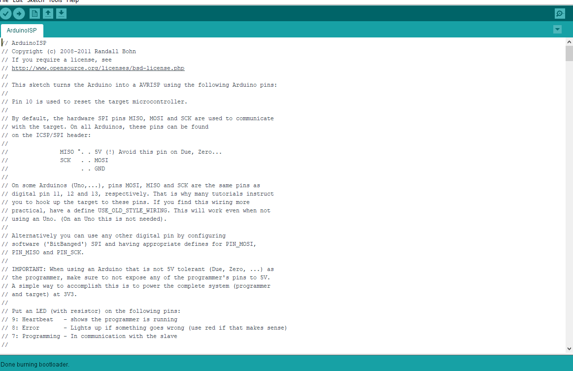
I first went to tools chose the following:
Board: ATtiny24/44/84
Processor: A Ttiny44
Clock: External 20 MHz
Port: I chose the port that was shown
Programmer: Arduino as ISP
And then chose “Burn Bootloader”
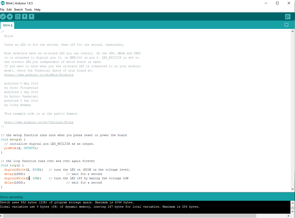
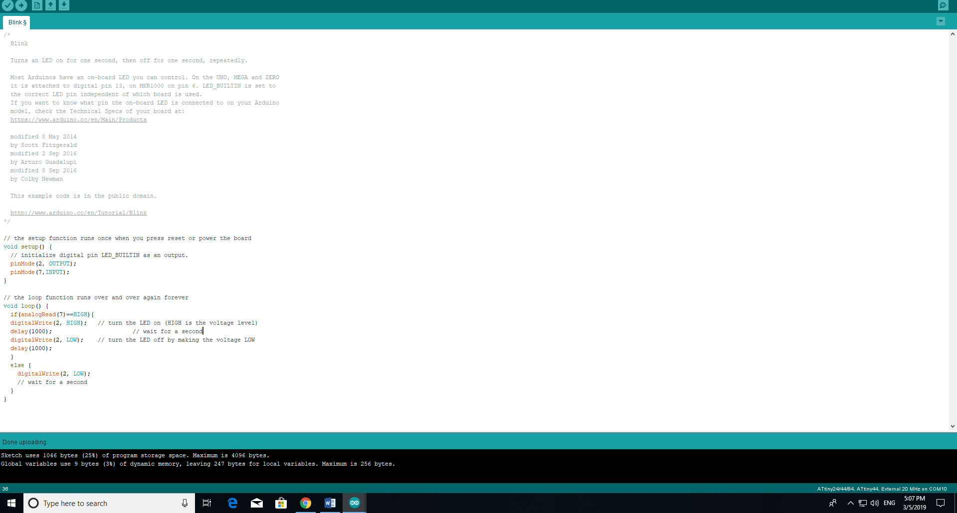
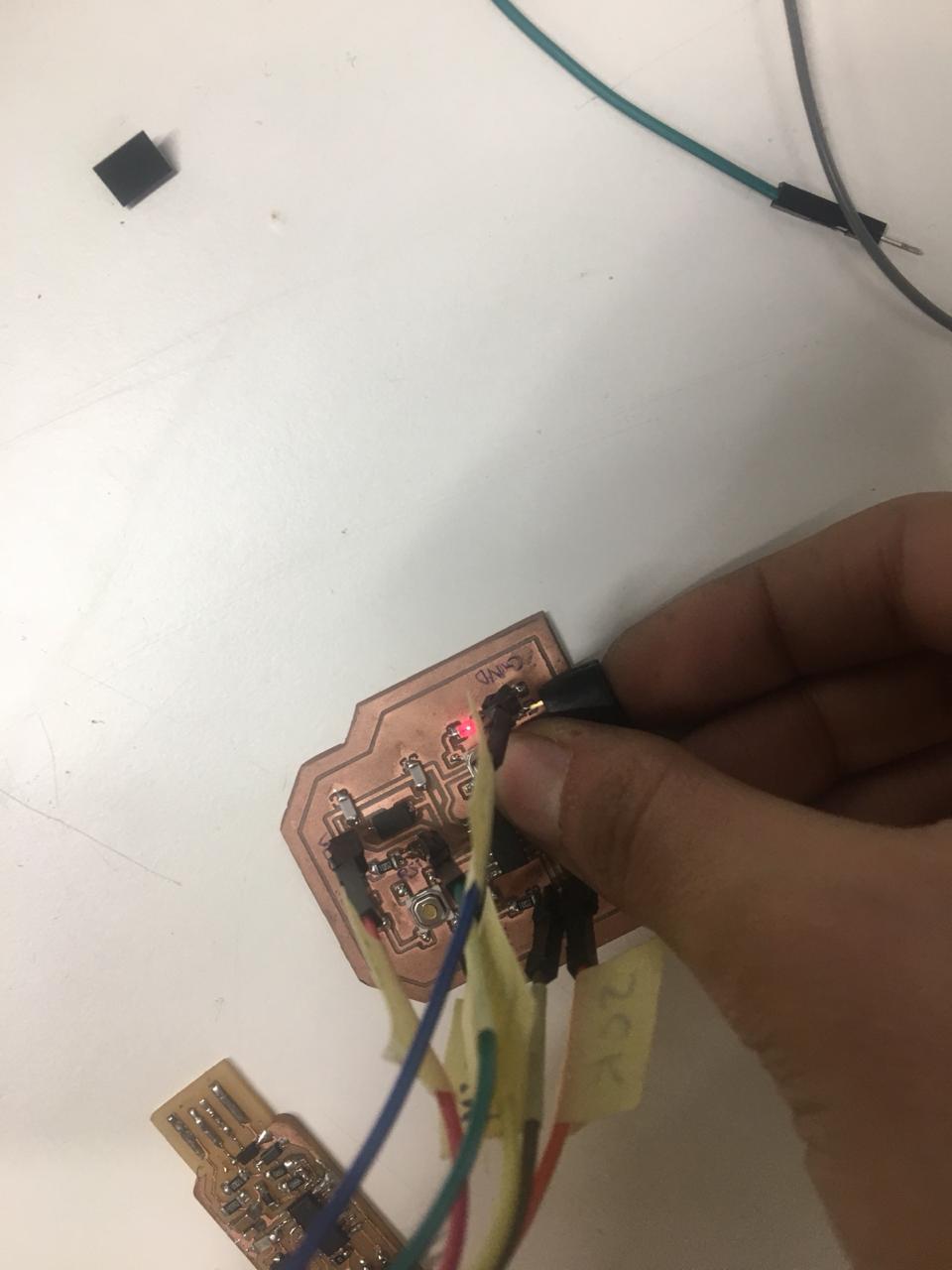
I then went to file, examples, basics, blink, and added pin number 2 which is connected to the lights, and then went to sketch, and added the lines shown in picture below for the button. Meanwhile, I faced a promblem with one of the pins, after looking further into the problem, I found out that it was because the VCC bpinhead wasn't soldered properly on the board, and so I soldered it again, and tested all the connections, and everything turned out to be in place :D I first uploaded the program using Arduino as ISP to check the board, it turned out to be working.
Then I uploaded using my FabISP, and tested my board. It was working, and I WAS DONE!