.png)
Hi! Welcome to Week 5
This week's assignment was to make an in-circuit programmer by milling the PCB,
programming it, then optionally trying other PCB processes.
This week's assignment was to make an in-circuit programmer by milling the PCB,
programming it, then optionally trying other PCB processes.
This week's assignment is to make an in-circuit programmer by milling the PCB, programming it, then optionally try other PCB processes.
This is my first time milling a PCB. I used Fab Modules the order, before uploading it to VPanel for SRM-20.
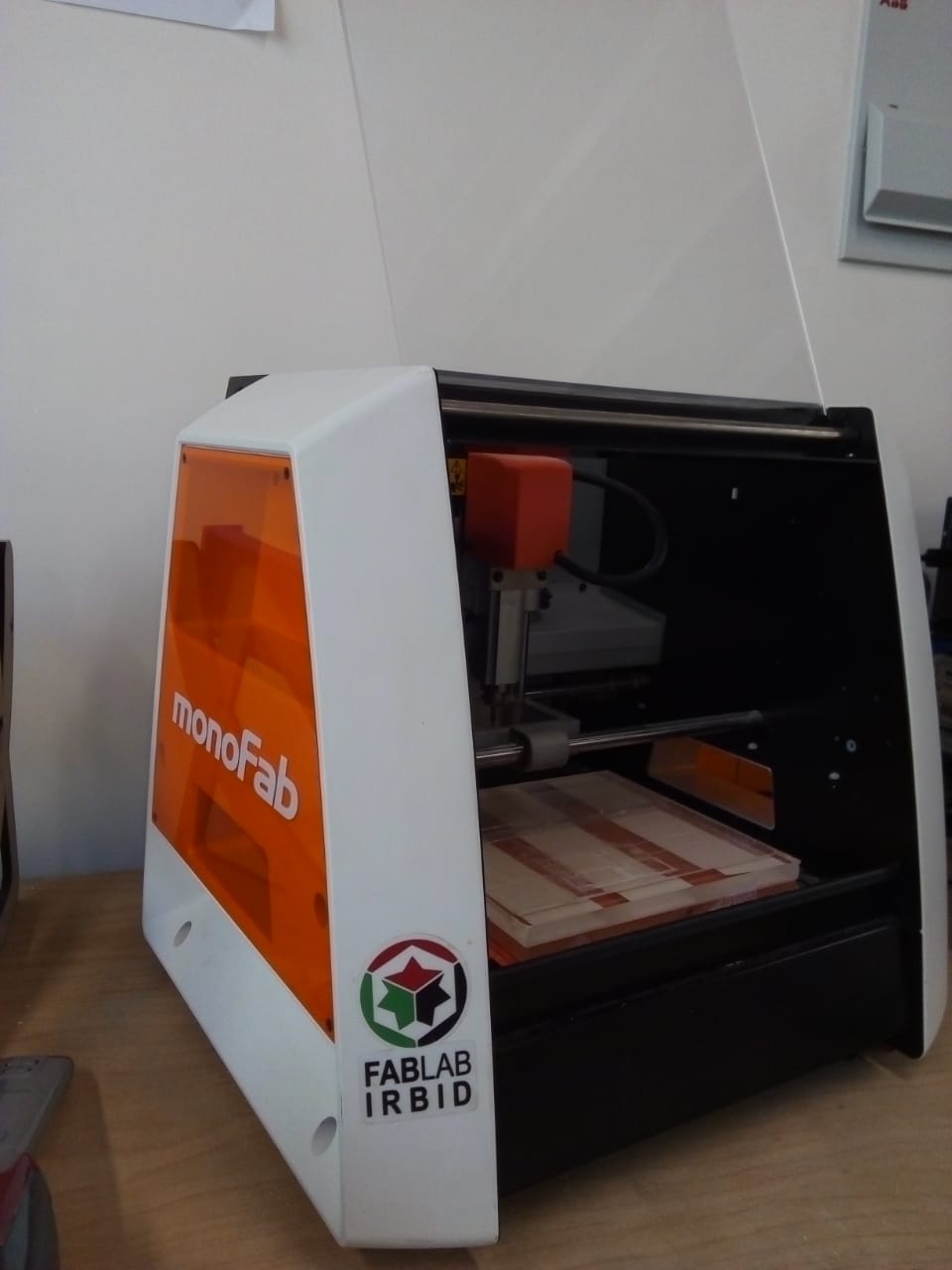
This week I’ll be using the SRM-20 milling machine.
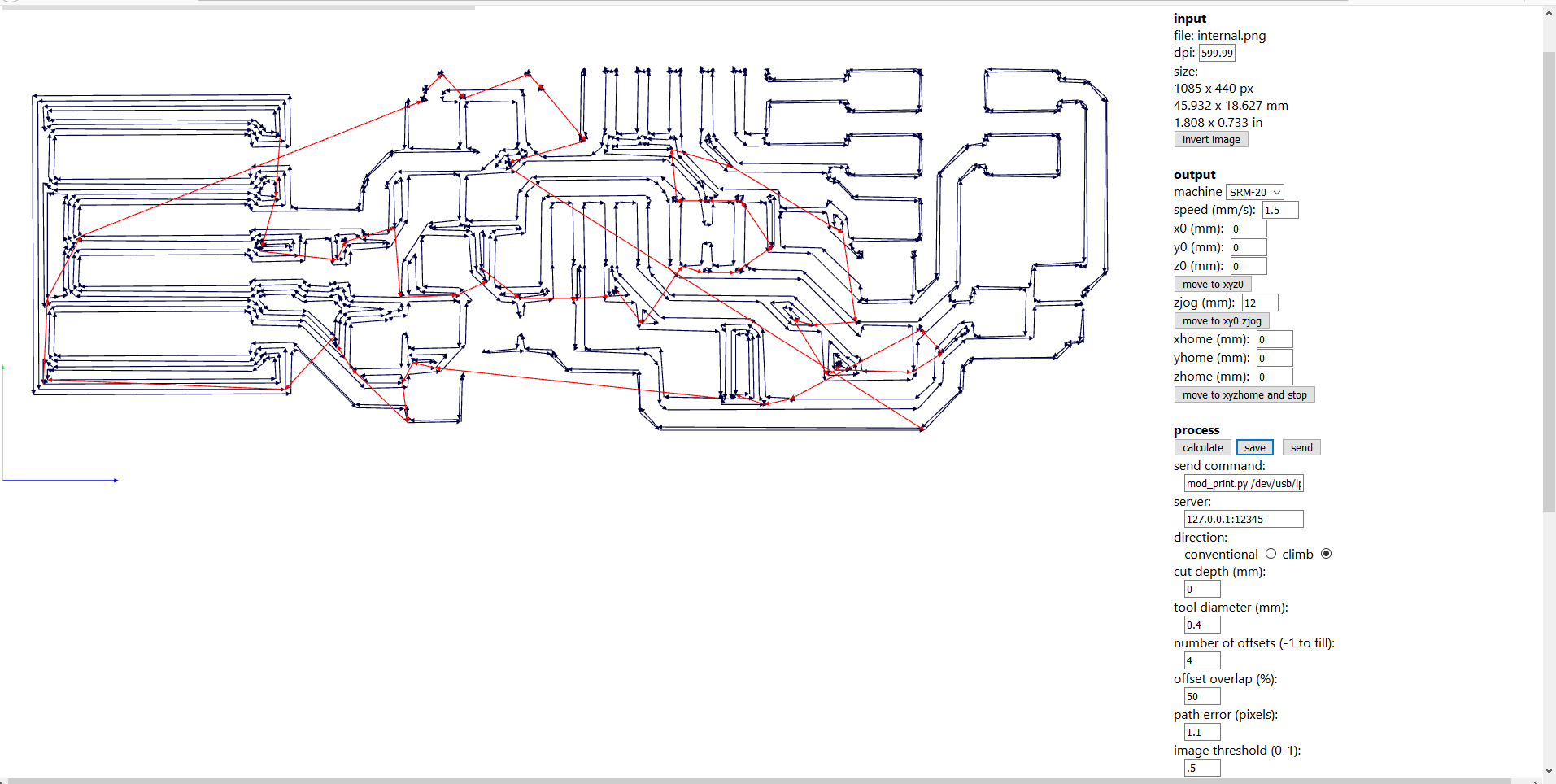
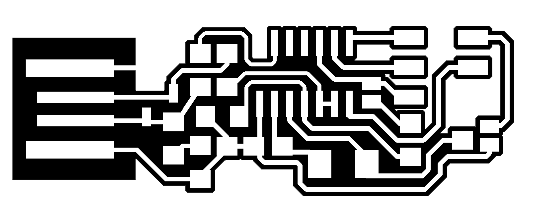
Here are the inner traces and the ourtline of which I’ll be milling and cutting:


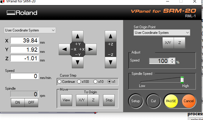
The first step week was to fix the PCB sheet to the bed of the milling machine using double face tape. Next, I opened VPanel for SRM-20 and used the arrows to move the bed and head as I wish in order to set the origin point. Setting X and Y was fairly simple, but setting Z needed a special process, I had to get as close to bed as I could, then use a multimeter between the sheet and the 1/64” cutting tool
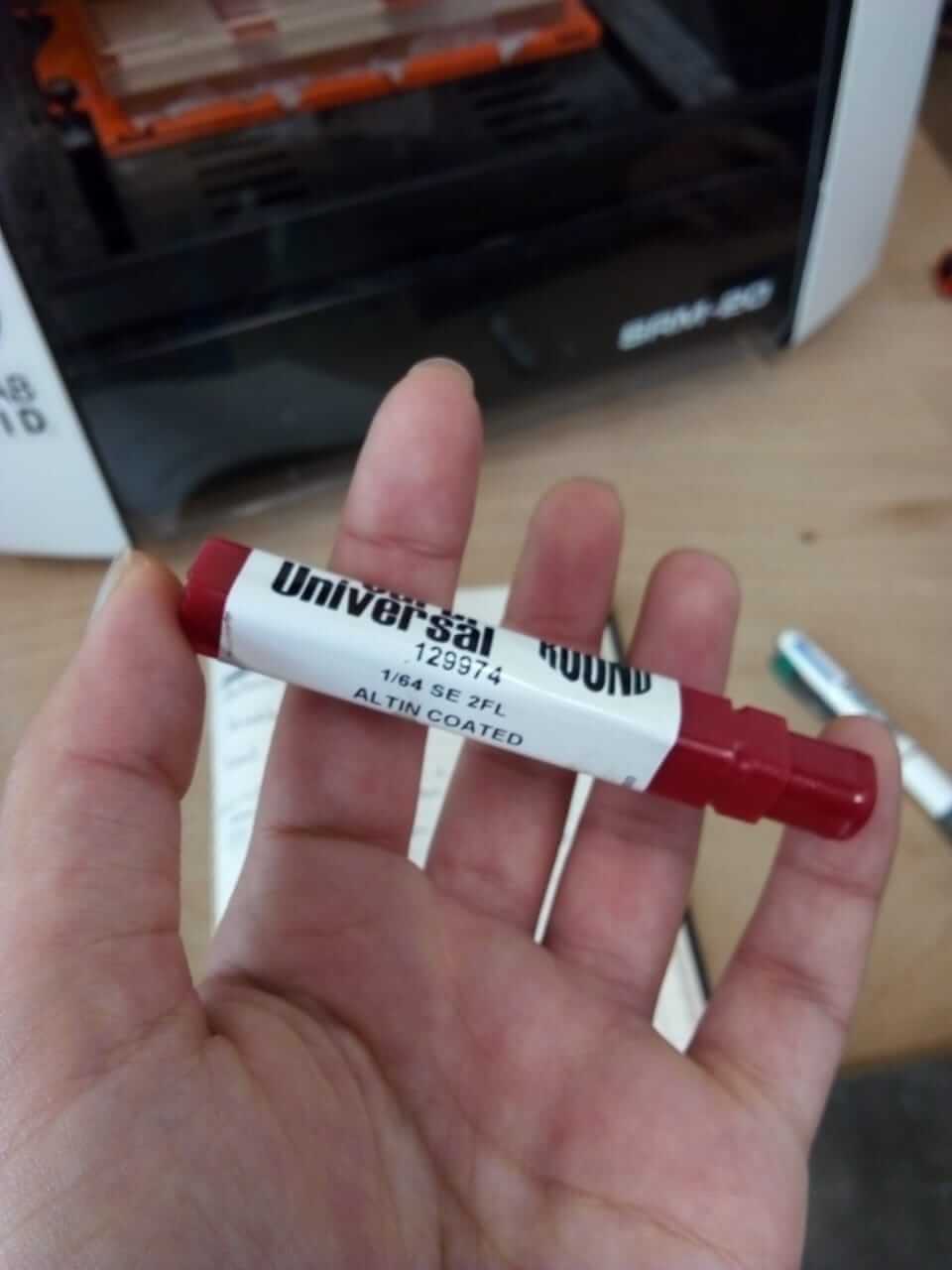
To check if they're connected. When I decided on the origin points I set them on the VPanel. As this was the first time using the machine on that day, I lifted the Z coordinates and ran the machine to warm it up. Next, I headed to Fab Modules , uploaded the image, the type of the machine and the cutting head size. I changed the output settings as follows:
and used this set up:
Then I clicked on calculate and save. On the VPanel I pressed on cut, uploaded the file and started the process.
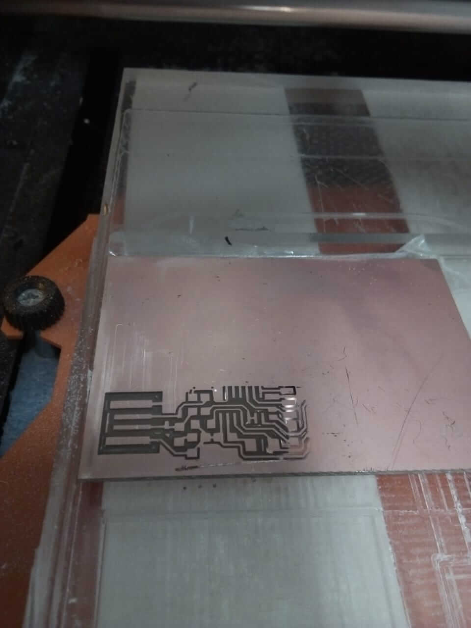
On the first trial, the output came out clean and smooth, but the problem was in the misalignment of the bed, and so some parts were not engraved.
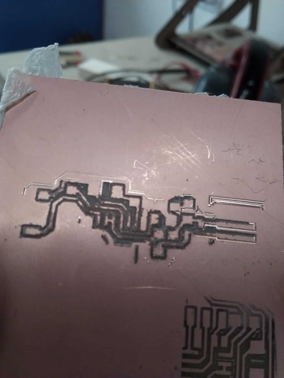
I tried it another time, and again some parts weren't engraved, so I lowered the Z origin point and repeated the order, however when I checked on the part the resulting surface this time was quite rough with bad finishing, this was due to the wearing of the cutting head.
In the third trial I changed the cutting head. I placed the used sheet in the middle of the bed and started the process, where I discovered that I haven't left enough place for the whole body (I gave it the same space as the first piece, which wasn't complete). As I was using a double face copper sheet, I flipped it and started the process once again, pausing the process every now and then to adjust the Z level to overcome the misalignment. On this trial, I had two problems, the first was that the higher part of the circuit wasn't engraved.
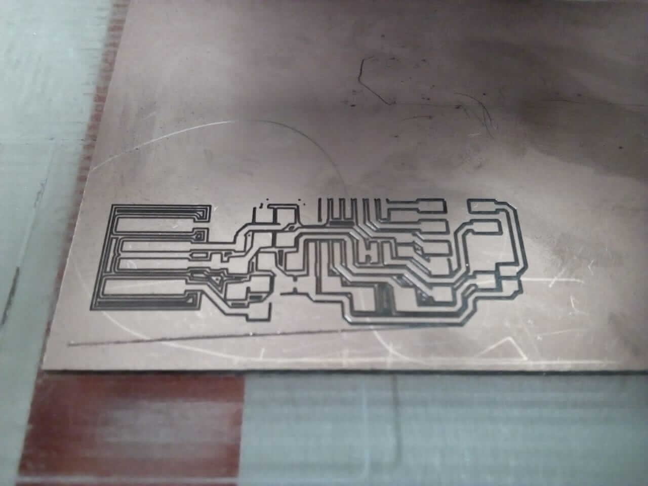
That was caused by the big size of the tool diameter I inserted on fab Modules. I changed it from 0.4 to 0.3 mm and the problem was solved. The other problem I discovered when the board was done is that some traces where erased.
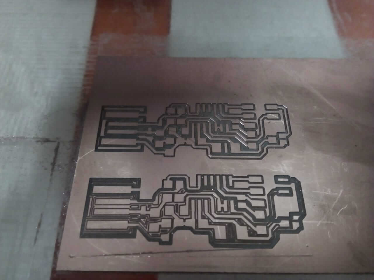
This problem could be solved by using a jumper but I preferred to print it again and I ended up pleased with the final results.
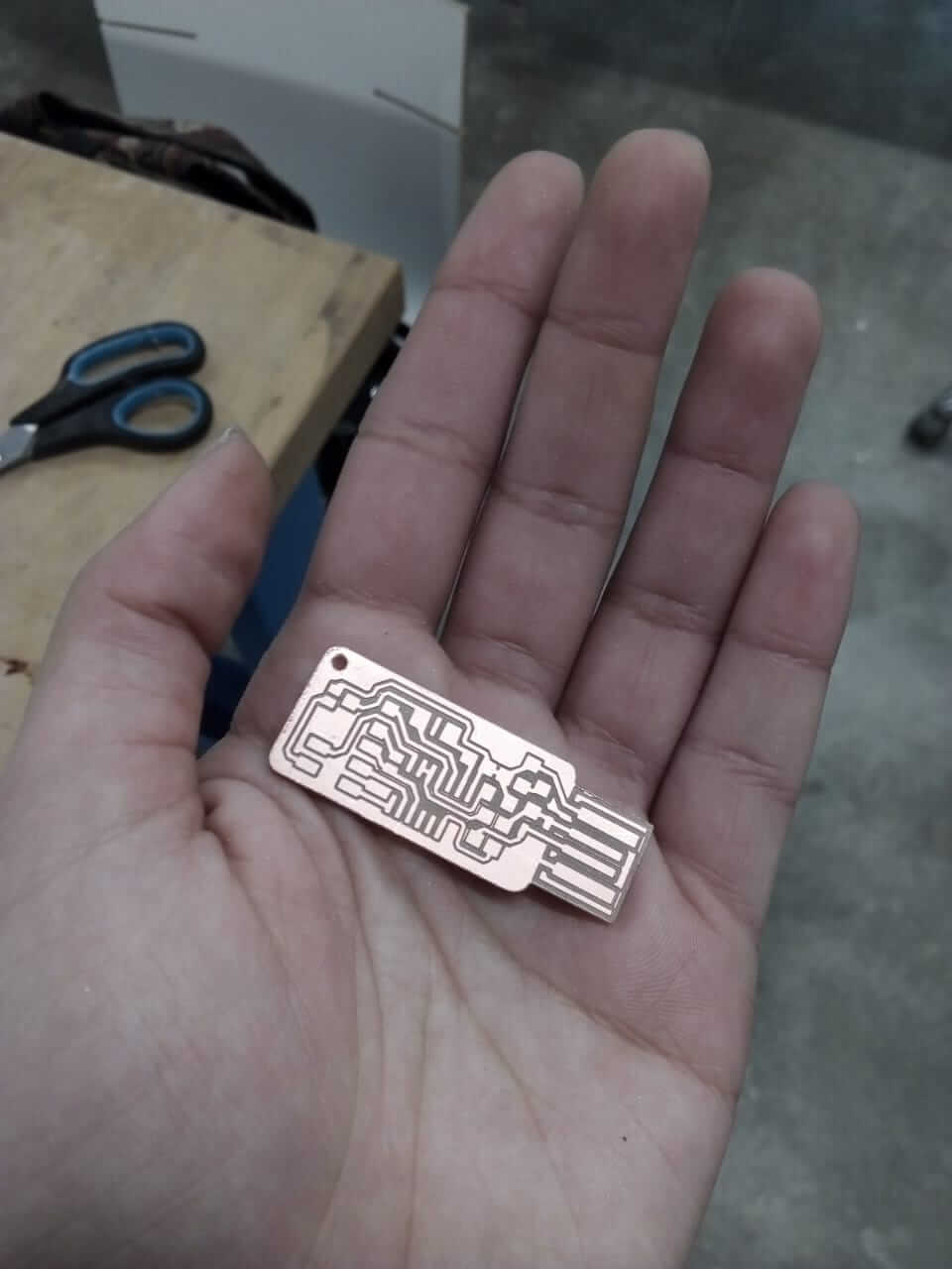
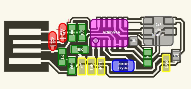
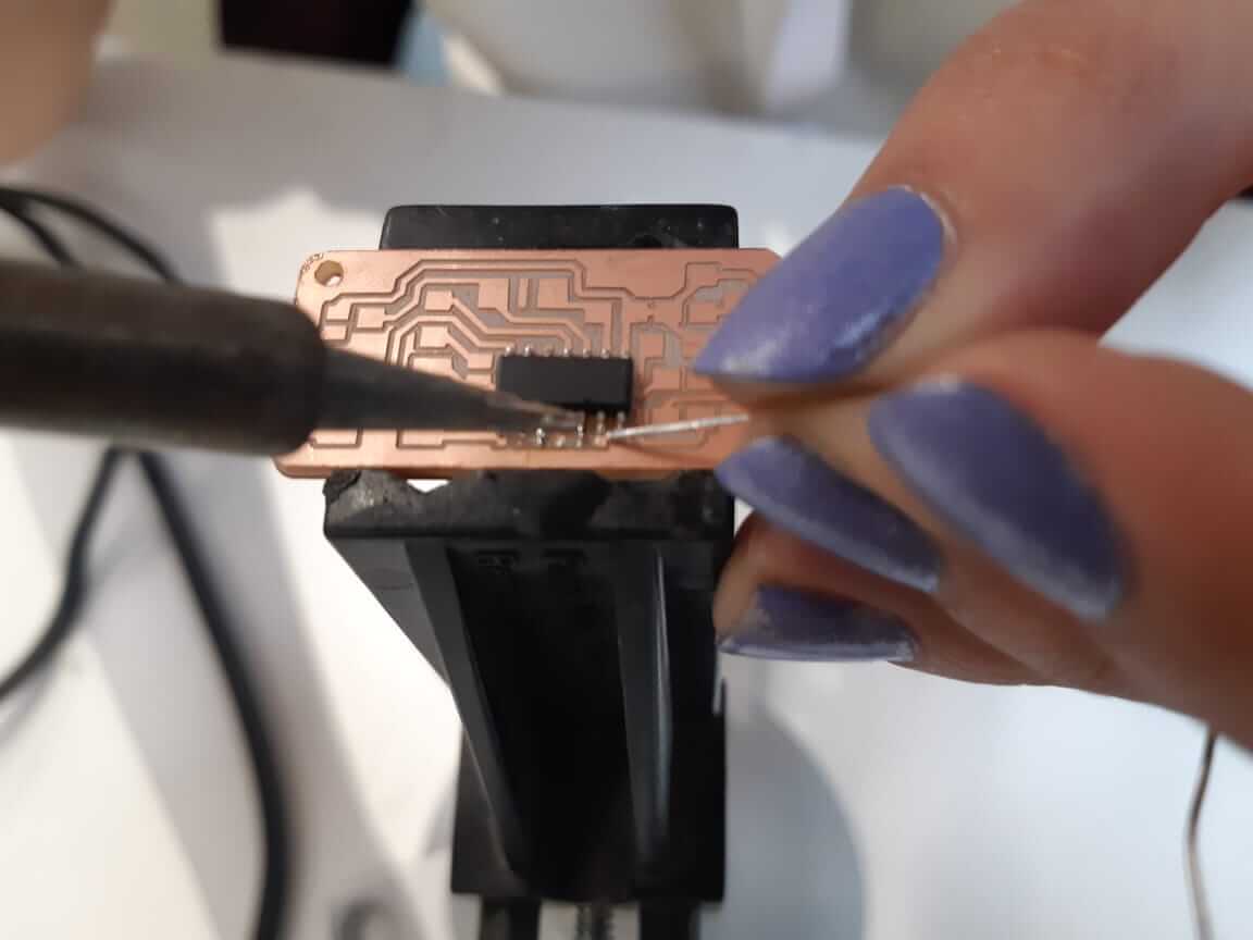
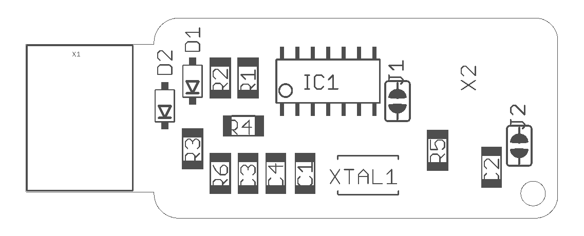
Next up it was time to solder the elements to the board. This was my first time soldering electronics, I sat the temperature of the soldering pin to 340 degrees, and soldered the pieces by following this illustration:
I added a little dot to the board, heated it again and fixed on side of the element, then added solder again to fix it in place.
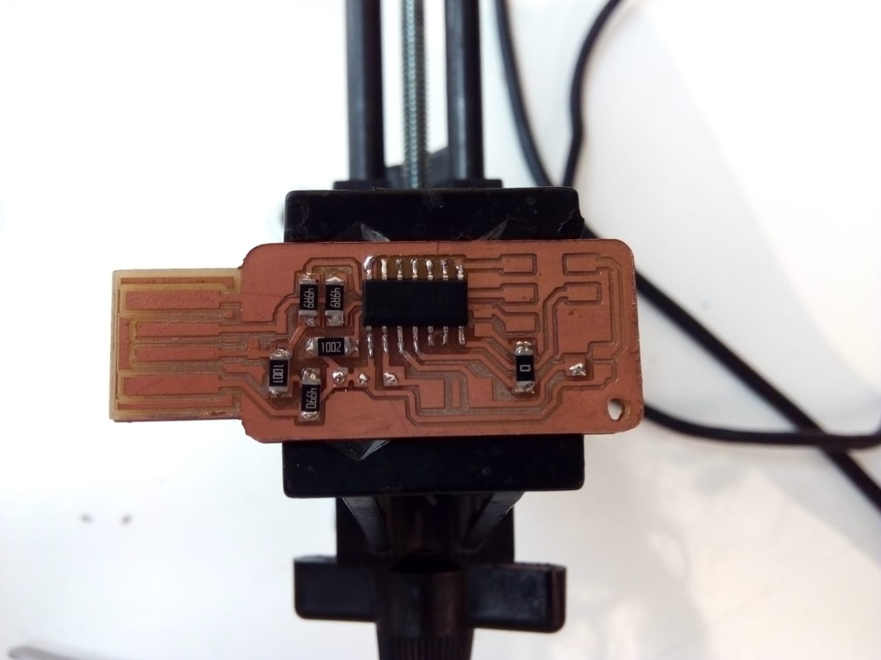
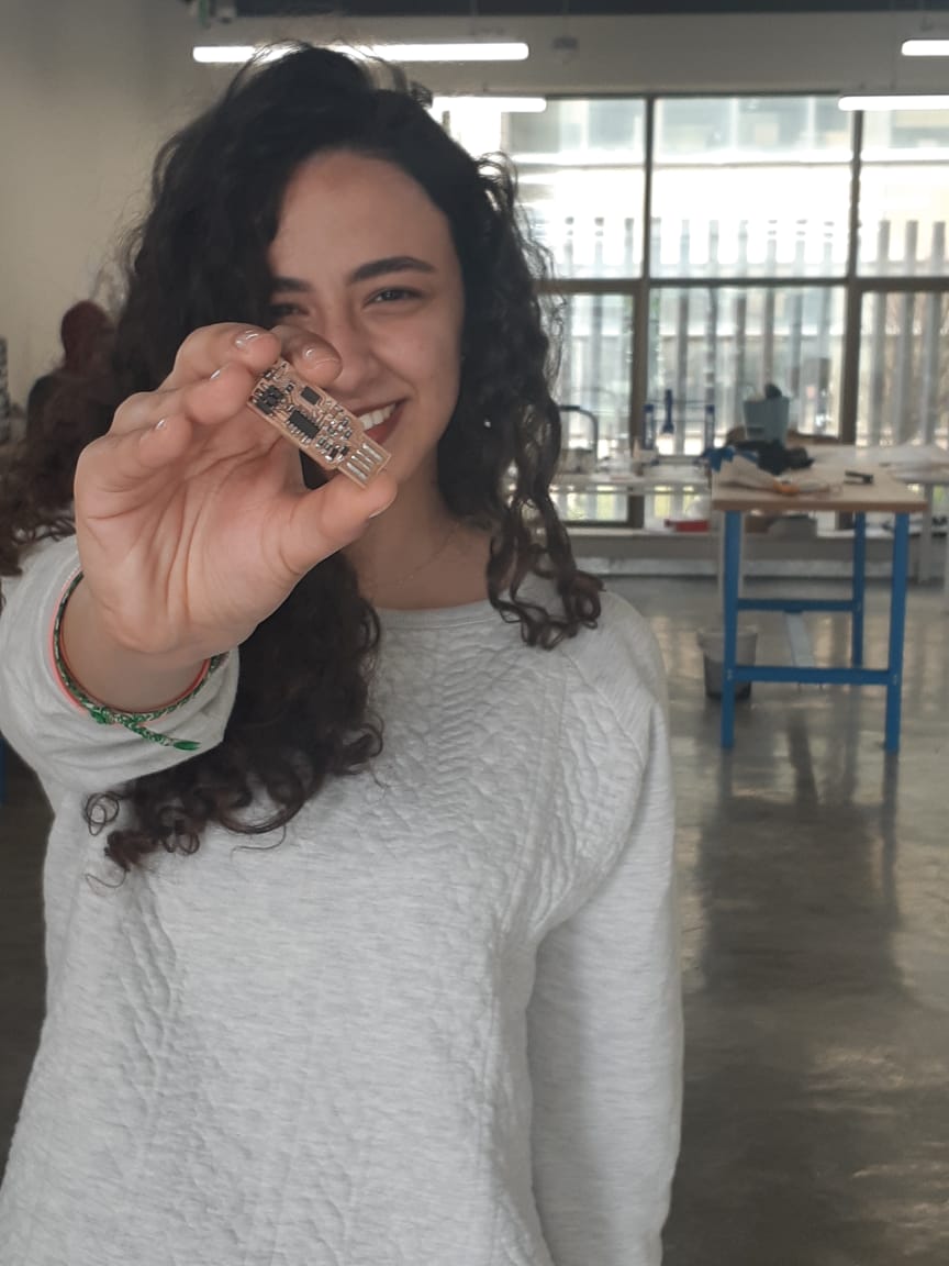
and I made sure that no two parts are connected where they shouldn’t be using a multimeter. This is what it looked like:

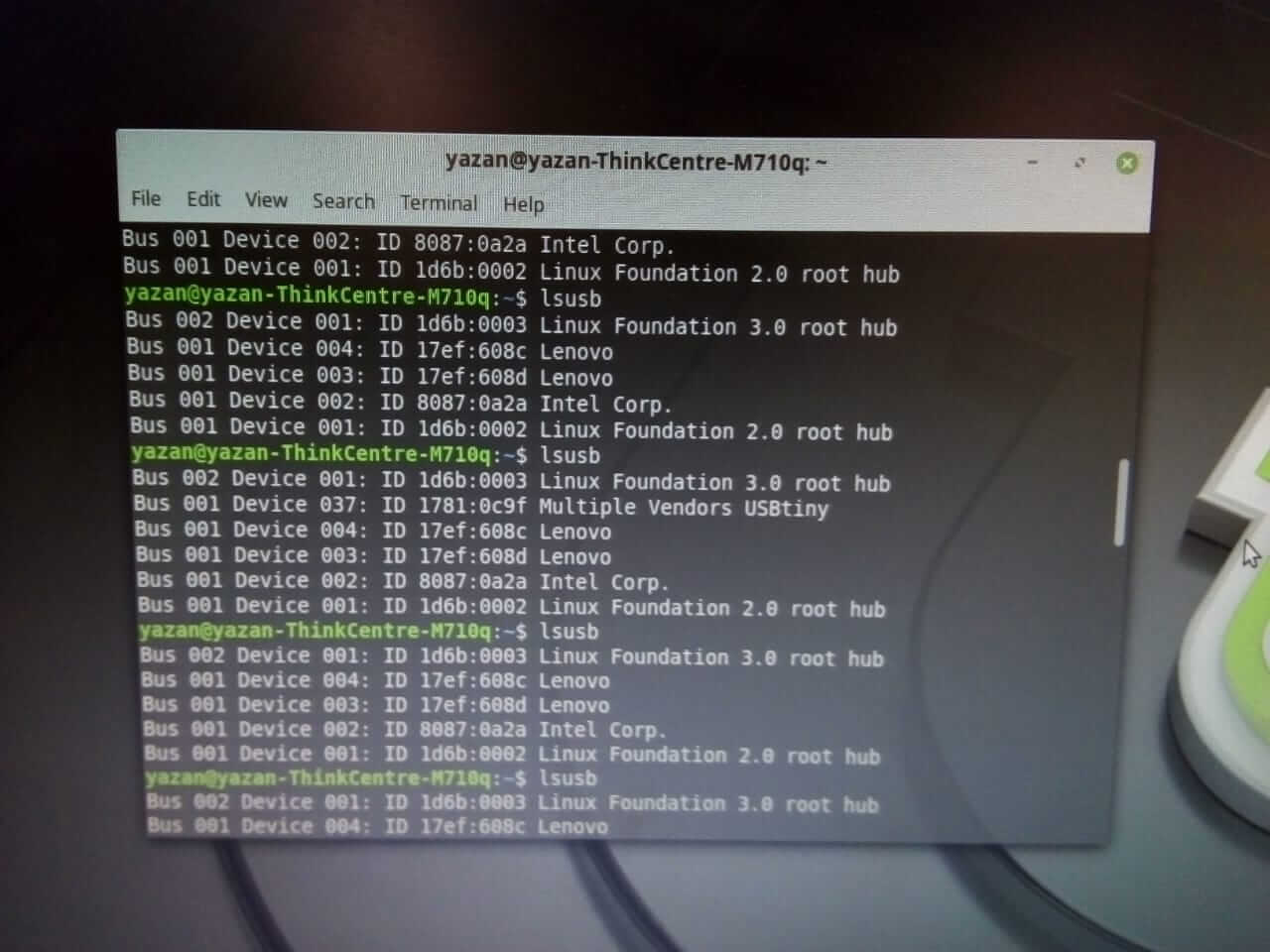
Programming the USB was going to be hard to use Microsoft Windows, so I tried Linux, and after few failed attempts I switched to Mac. I connected the laptop to an Arduino programmer. I used an Arduino Uno and connected it to the laptop, then connected my USB to the Arduino board and followed the instructions on this tutorial to program it where I first downloaded the necessary drivers and packages using:
           sudo apt-get install flex byacc bison gcc libusb-dev avrdude
sudo apt-get install gcc-avr
sudo apt-get install avr-libc
sudo apt-get install libc6-dev
Now, I am going to use the Arduino board as a programmer to make my ISP a programmer (confusing, I know). Here I connected
The main orders where: | My ATtiny44 Pin | Arduino Pin |
|---|---|
| 4 (Reset) | 10 |
| 7 (MOSI) | 11 |
| 8 (MISO) | 12 |
| 9 (SCK) | 13 |
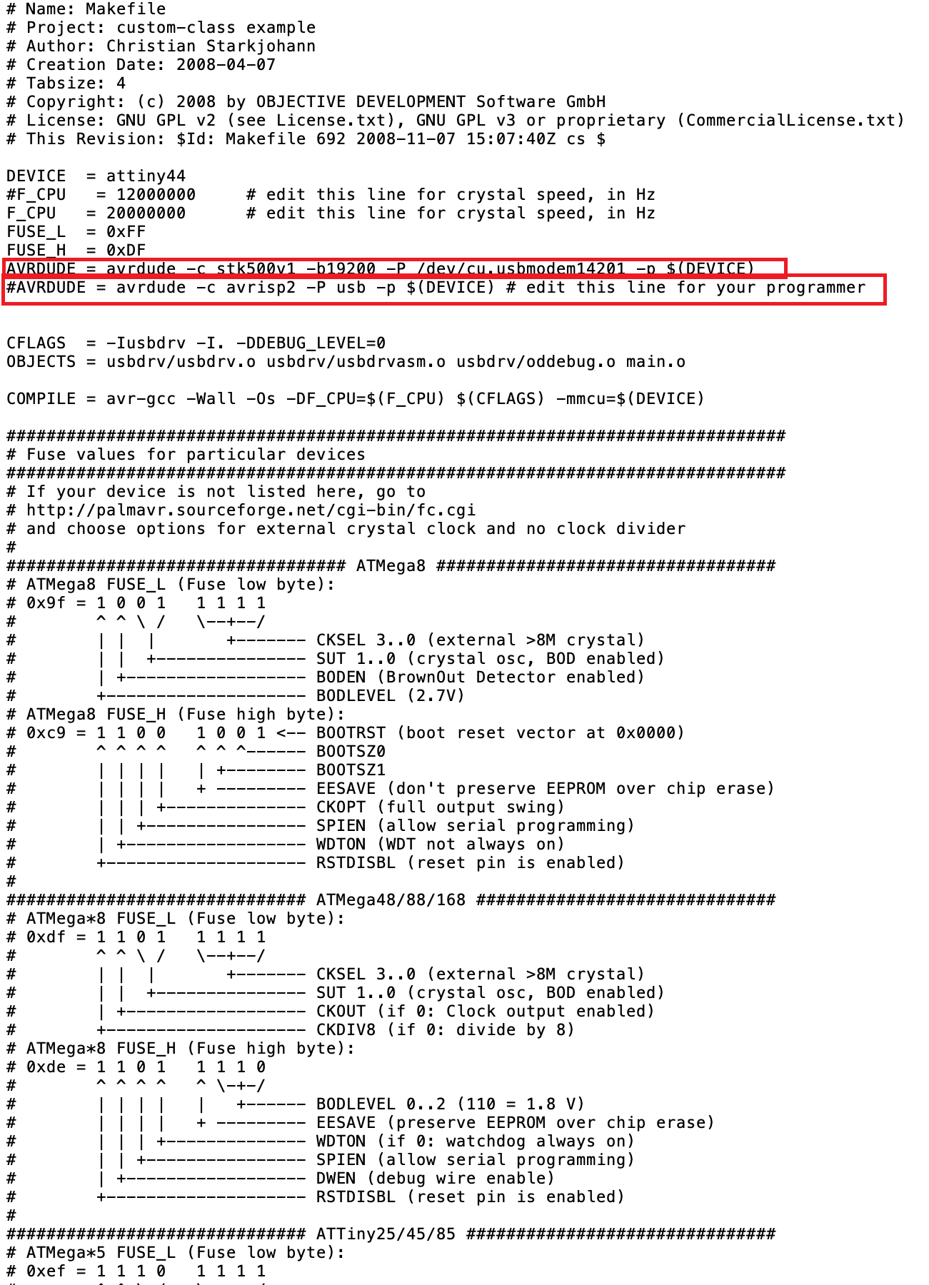
cd ~/Desktop
wget http://academy.cba.mit.edu/classes/embedded_programming/firmware.zip
unzip firmware.zip
Then, I opened the Make File, and commented the following line by adding a hashtag in the beginning:
AVRDUDE = avrdude -c avrisp2 -P usb -p $(DEVICE)and then typed:
AVRDUDE = avrdude -c stk500v1 -P /dev/ttyACM0 -b19200 -p $(DEVICE)Here, you can see my edit on my file: