.png)
Hi! Welcome to Week 12
This week’s assignment was add an output device to a microcontroller board I've designed, and program it to do something!
This week’s assignment was add an output device to a microcontroller board I've designed, and program it to do something!
For this week, I am going to make a story board in the shape of a box, that is going to be controlled by a button that will cause the stepper motor to rotate, and I will also use lights that will be placed in the box, and will cast it’s shadow on a wall. I designed the box using festi, I simply added the dimensions that I would want for my box and the type of joint I want and the website generated the 2d plans for the box ready for cut, you can download my box from here . Since I do not have CorelDraw on my laptop, I prepared the file using InkScape, with was a bit tricky but this tutorial helped me maneuver with the program, and I added the drawings I want on each side, Here are the files for the drawings, Which were made by my sister Diana Habashneh. Next, I added a circle in the center of the sides, where the rod will pass through, and I then laser cut the plans.
So now back to CorelDraw, I made the dimension of the drawings Hairline, and then proceeded to cut it using the Laser machine. After I finished this par, I drew the gear and the base, and again cut the using the laser machine.
After this part, I prepared the board that will be used along with the device. I wanted the device to be able to operate anywhere and so I added a micro USB port.
I assembled the pieces together, and now I had to think on the rotating mechanism, and the electronic board.
I used a stepper motor, whichA stepper motor converts electronic signals into mechanical movement each time an incoming pulse is applied to the motor. Each pulse moves the shaft in fixed increments. If the stepper motor has a 1.8° step resolution, then in order for shaft to rotate one complete revolution, in full step operation, the stepper motor would need to receive 200 pulses, 360° ÷ 1.8 = 200.
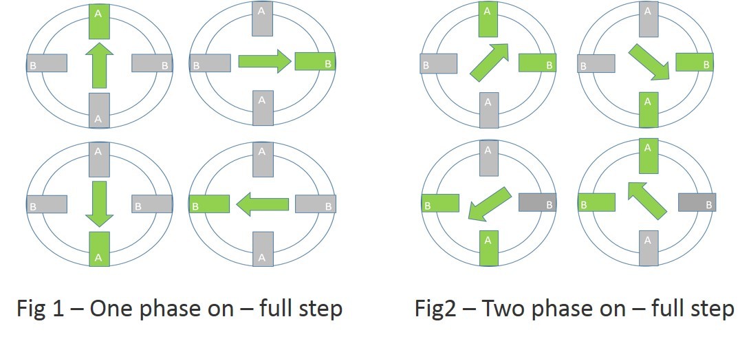
There are two types of full step excitation modes.
In one-phase on - full step, Fig1, the motor is operated with only one phase energized at a time. This mode requires the least amount of power from the driver of any of the excitation modes.
In two-phase on - full step, Fig2, the motor is operated with both phases energized at the same time. This mode provides improved torque and speed performance. Two-phase on provides about 30% to 40% more torque than one phase on, however it requires twice as much power from the driver.
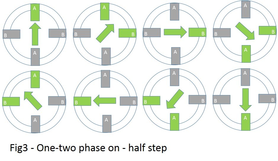
Half step excitation mode is a combination of one phase on and two phase on full step modes. This results in half the basic step angle. This smaller step angle provides smoother operation due the increased resolution of the angle.
Half step produces about 15% less torque than two phase on - full step, however modified half stepping eliminates the torque decrease by increasing the current applied to the motor when a single phase is energized. See Fig3
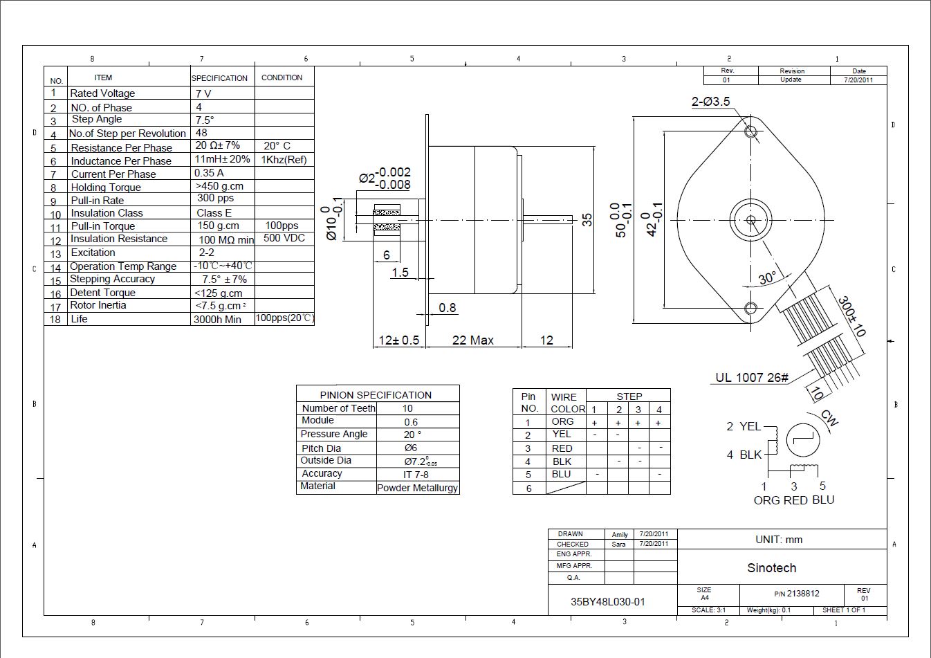
This is the data sheet of the stepper I used, from it, you can see that there are 4 wires connected that control the rotation, while the orange one is idle.
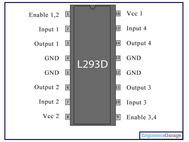
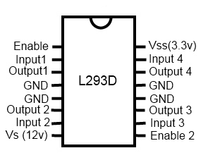
Another new component I used this week is the H-bridge which is an electronic circuit that switches the polarity of a voltage applied to a load. These circuits are often used in robotics and other applications to allow DC motors to run forwards or backwards. You can check the data sheet for the L293D I used from here.
This is my schematics, I added the microUSB in order to power the motor with out the need of an arduino board connected to the computer. The drive is an essential component when using a stepper motor, I followed an online tutorial and connected the GNDs and VCCs, for each wire of the 4 wires I used, a wire was connected to the IC, and a correspondent pin was taking a signal from the ATmega. I added 2 buttons, one for reset and the other one to give signal to the ATmega to rotate the stepper motor.
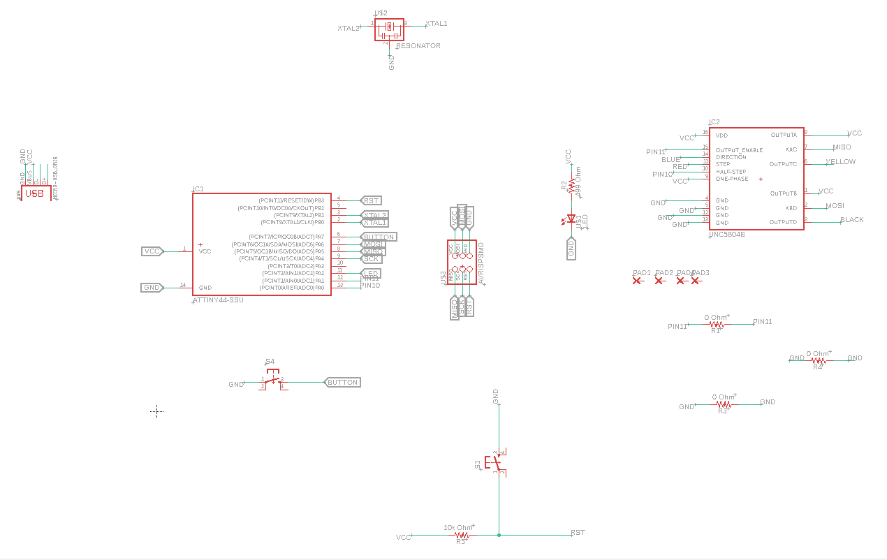
Also, since I was using a stepper motor this week, I checked the data sheet, and also added an H bridge driver to the board and connected it according to its pinout.
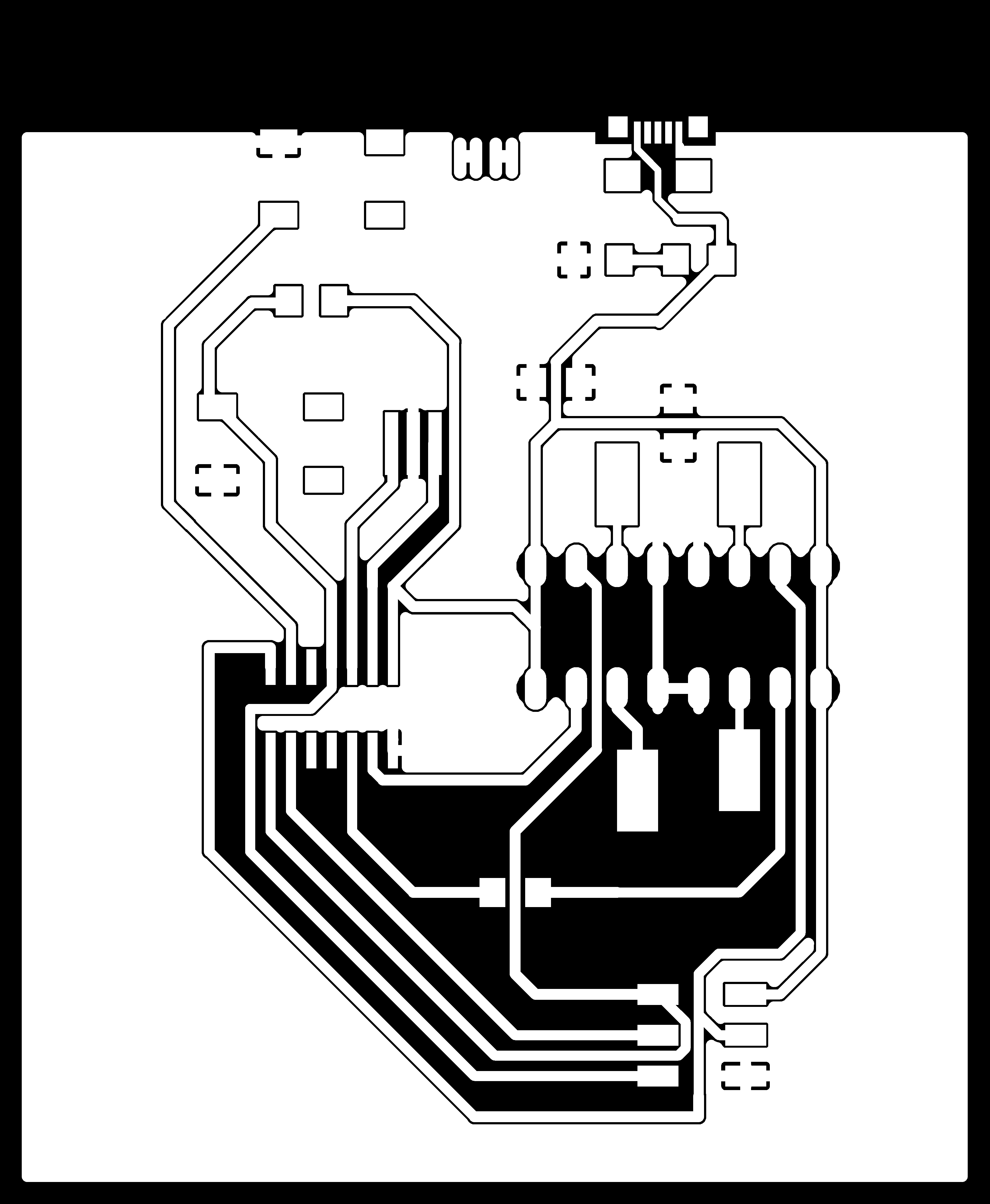
Here you can download the schematics, and the board.
Here you can download the traces, holes, and outline.

I soldered all the electronic parts to the board except for the motor, but it turned out after testing the board that I had burned the H bridge. I removed it and the soldered a pins extension, this way I could avoid burning it again as it's a sensitive part.
Before programming my board, I had tested this program using an Arduino board and bread board just to ckeck if my code did what I wanted it to do. With this code, I used the "Stepper.h" library in order to get access to many functions, like setting the speed and the number of steps I want it to take (by deviding the steps per revolutions/ on the number of faces I have) I want, which has cut a lot of the time in programming the board. This is the code I used:
#include  <Stepper.h>

const int stepsPerRevolution = 48;
int PushButton = 5;
// initialize the stepper library on pins 8 through 11:
Stepper myStepper(stepsPerRevolution, 8, 9, 10, 11);

void setup() {
  pinMode (PushButton, INPUT_PULLUP);
  myStepper.setSpeed(30);

  Serial.begin(9600);
}

void loop() {
  int readPushButton= digitalRead (PushButton);
if (readPushButton == 0) {
  Serial.println("clockwise");
  myStepper.step(stepsPerRevolution/6);
  delay(500);

}
}
.jpg)
.jpeg)
.jpg)
.jpg)