


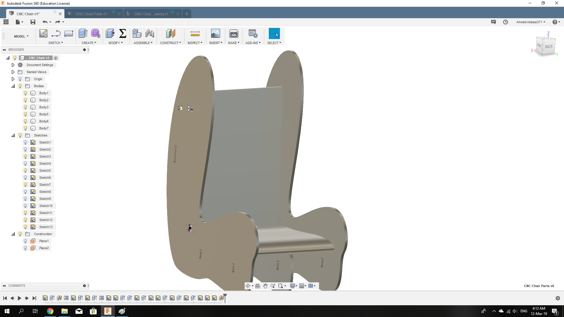
For this week, I had to design and create something of a big size using the CNC machine. My plan was to make a chair with an adjustable back. I started with knowing what the available material is. In the lab, we had Latte and Plywood. The sizes of the boards are the same: 2440x1220x18 mm.
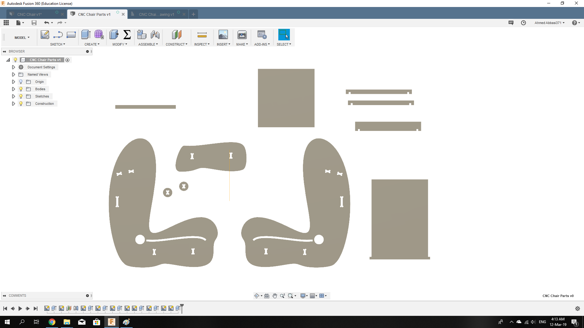
I have designed my chair using Fusion 360 by creating it as a 3D assembled model first, then I started copying the sketches of each face to a new file to arragne them in 2D.
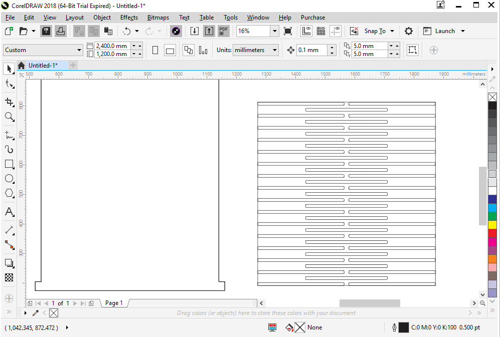
I added a living hinge to make the seat able to bending. Using CorelDraw, I openned a file I downloaded from an opne source (thingiverse) that has a living hinge used in its design. I copied the living hinge and pasted it in my file, then adjusted the dimensions to be suitable to my seat.
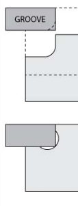
In the desing, you can notice the dog-bone shaped joints. Those are made to make the fitting possible, because if they were'nt designed like that, but rather only a normal rectangle, the end-mill will cut it leaving a champher in the corners with 3mm radius (half the end-mill's diameter) which would prevent the other part from fitting inside the joint.
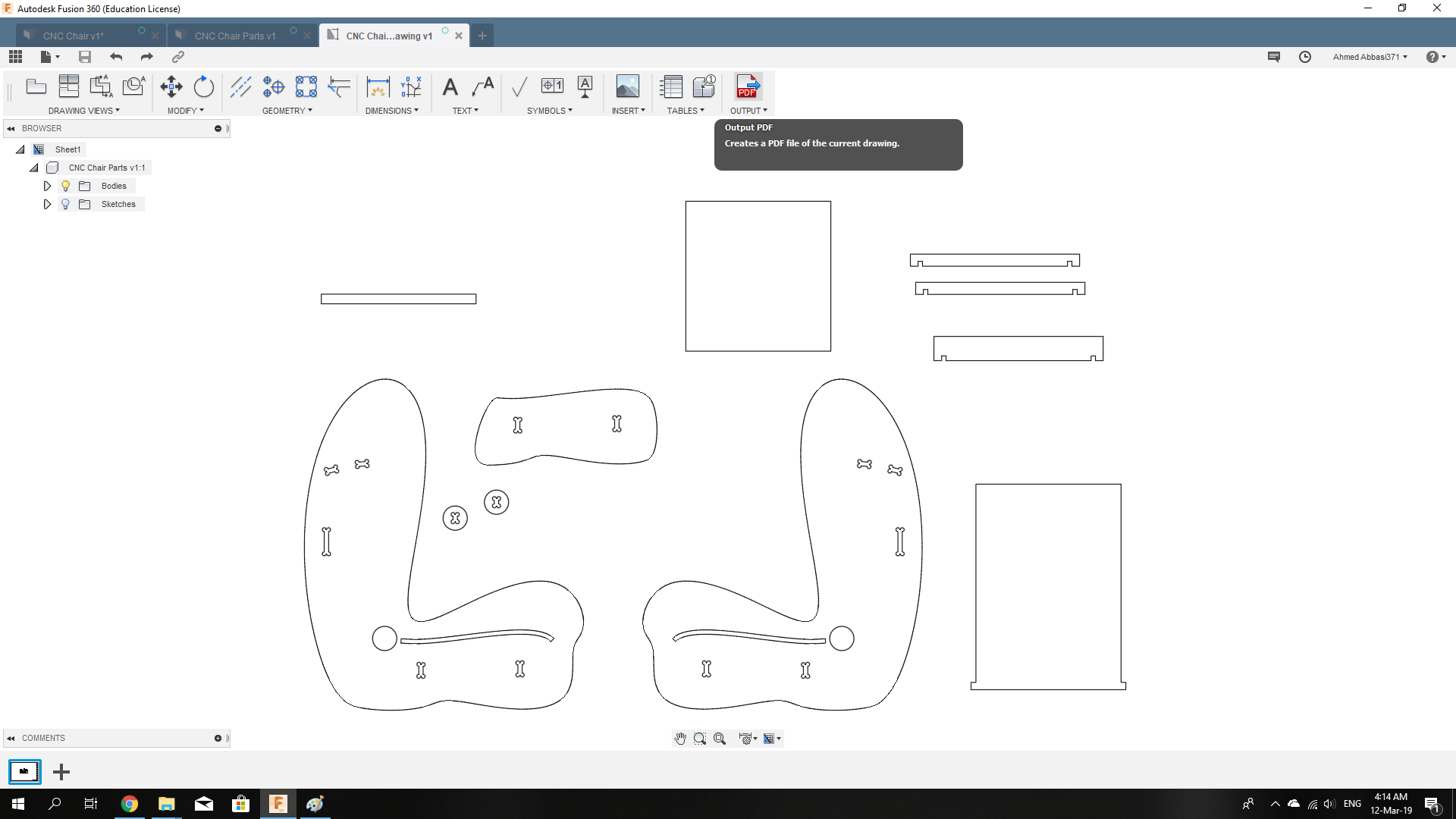
Note: To make the curvature of the chair sides, I first drew rectangles with the dimensions i want, then using the spline tool, i satrted drawing and then adjusting the curves.
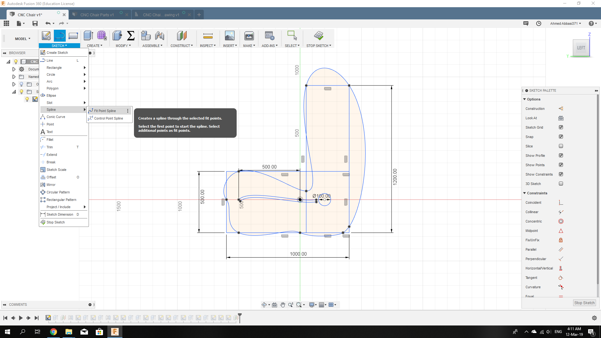
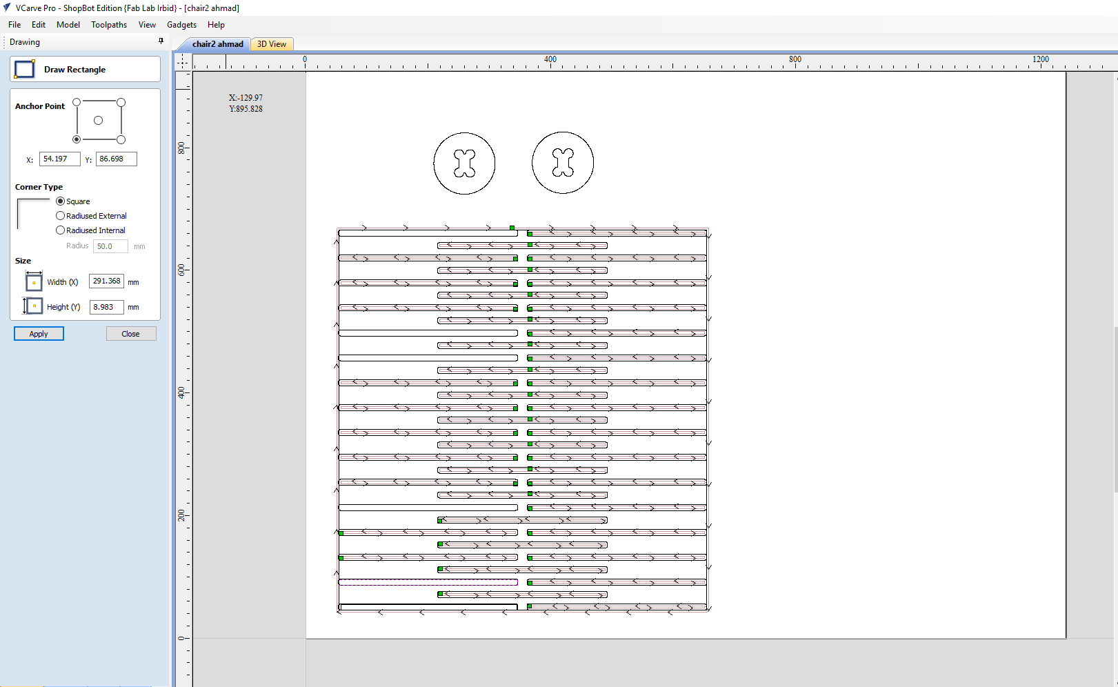
Saving the drawing as a .dxf file, I openned it using VCarve software so i can arrange the parts to fit inside the board.
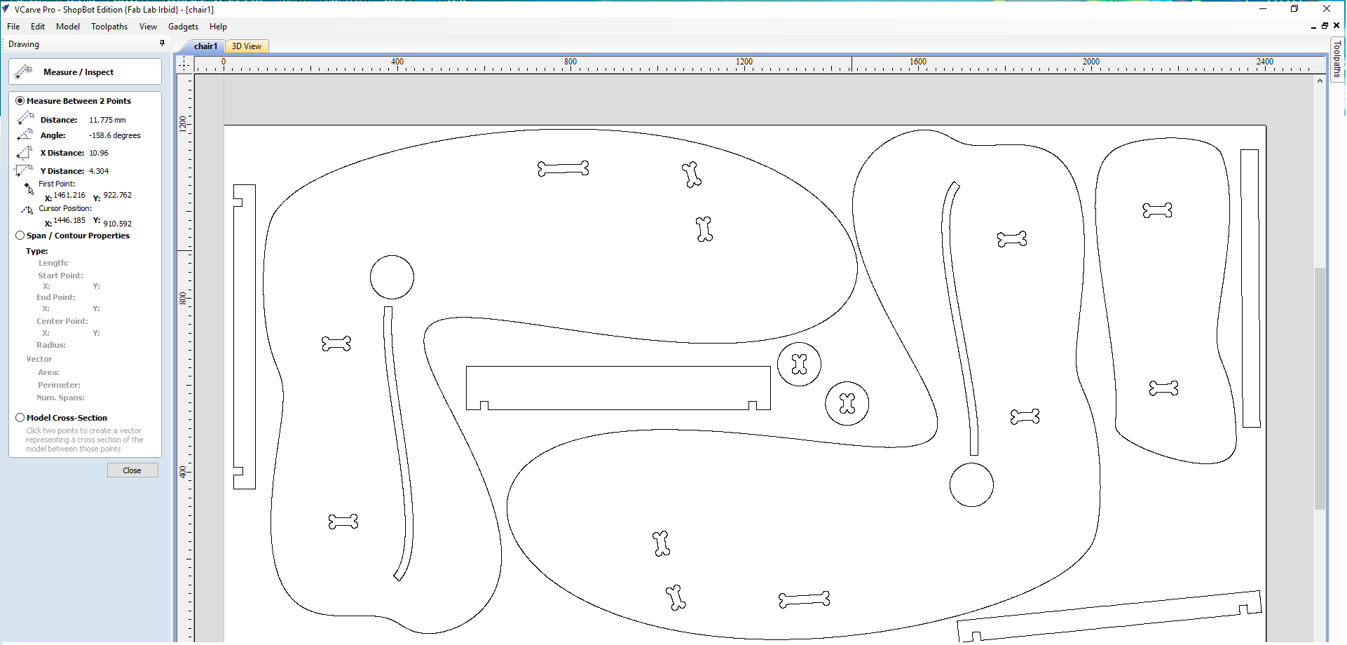
When you upload a file to VCarve, the first thing it lets you do is to adjust the dimensions of your board. so I set them to 1200mm (y-axis) and 2400mm (x-axis). I left 2cm for fastening the board, as there will be bolts holding it to the machine's bed. We'll come to that later.
In the above picture, we can see to the left that the measuring tool is active, we use it to make sure that the clearence between the parts' edges is more than 6mm (End-mill diameter) so there wont be an overlap in the cutting.
Not all the parts fit into one board, so the seat and back where lift to be done on a second board.
On the right there is the toolpath button clicking on it then choosing 2D Profile Toolpath we'll have this window:
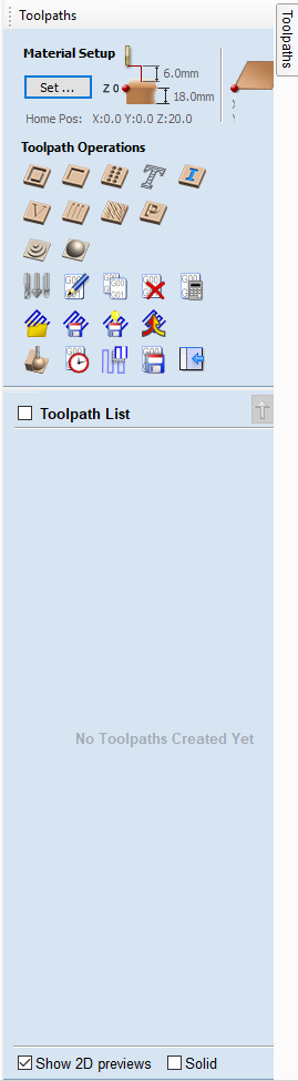
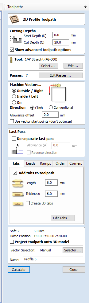
First division: Cutting depth; we selected it at 20 mm to make sure that it will cut throught out 18 mm board.
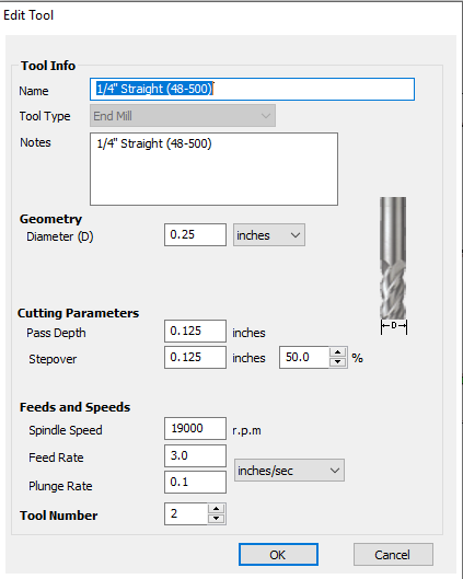
Second division: Tool; There we select the settings for the tool we're using, like its diameter and the speed at which we want it to rotate.
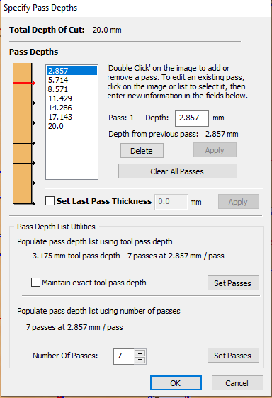
Then there is the passes, those manage how many laps are going to pass over each line till it is cut through. Here, we have a 20mm depth selected, and the passes we chose for them to be 7 passes, which is reasonaable to get a better finnishing and less load on the mill. Hence the depth of each pass will be automatically set to 20/7=2.85 mm.
Third division:Machine vectors; here we select the path in which we want the mill to travel so it wont cut from our design part.
A problem ocurred with me and I think it happened when I uploaded the file to VCarve, is that some of the curves separated from each others and oppen loops existed.
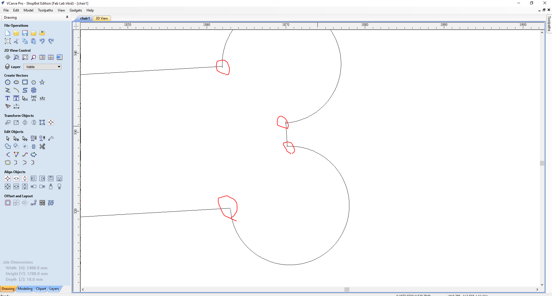
This caused issues in selecting the toolpath, so I had to make an Outside path for the straight-lines and Inside path for the archs. Anyhow, the accuracy was not very favourable and the cutting took more time due to the dincontinuity in lines.
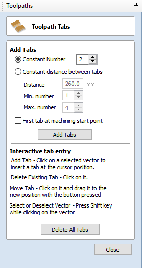
Fourth division: Tabs; small tabs could be added between the parts and the main board to keep them attached so no slipping would occur. There usage and importance will be explained further.
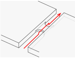
Tabs could be added manually in selected points, or automatically by the computer by clicking Add Tabs.
A problem occurred when selecting a toolpath. Some of the lines in the living hinge were not defined. And as the living hinge sketch was totally grouped, I had to draw rectangles overlining the ones that were not defined, then creating a path for them.
After the setup, we click on Calculate so the functions will be applied to the drawings.
From the Toolpath window, pick Preview Toolpaths.
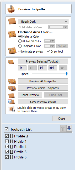
This is useful to make sure that there is no overlapping nor anything missing.
Finelly, and also from the Toolpath menu, select Save Toolpath. That will export a G-code to a selected directory.
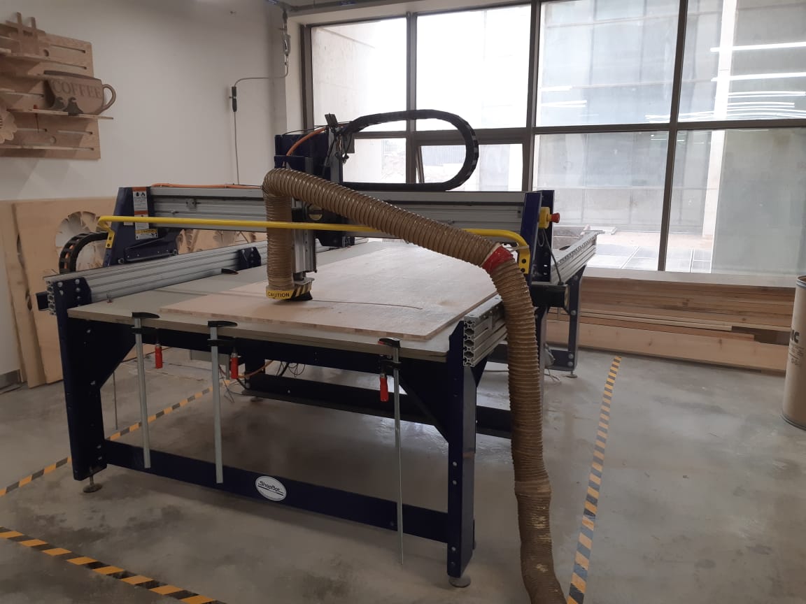
The software used for this machine is called Shopbot.
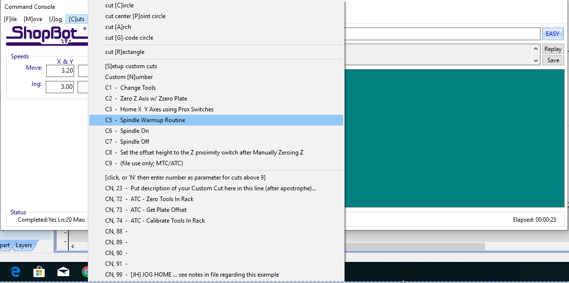
Before everything, we need to warm up the machine, this process takes up to 30 minutes. It is advised that we do this before setting the design on VCarve in order to save time. To do that, we click on [C]uts>Spindle Warmup Routine.
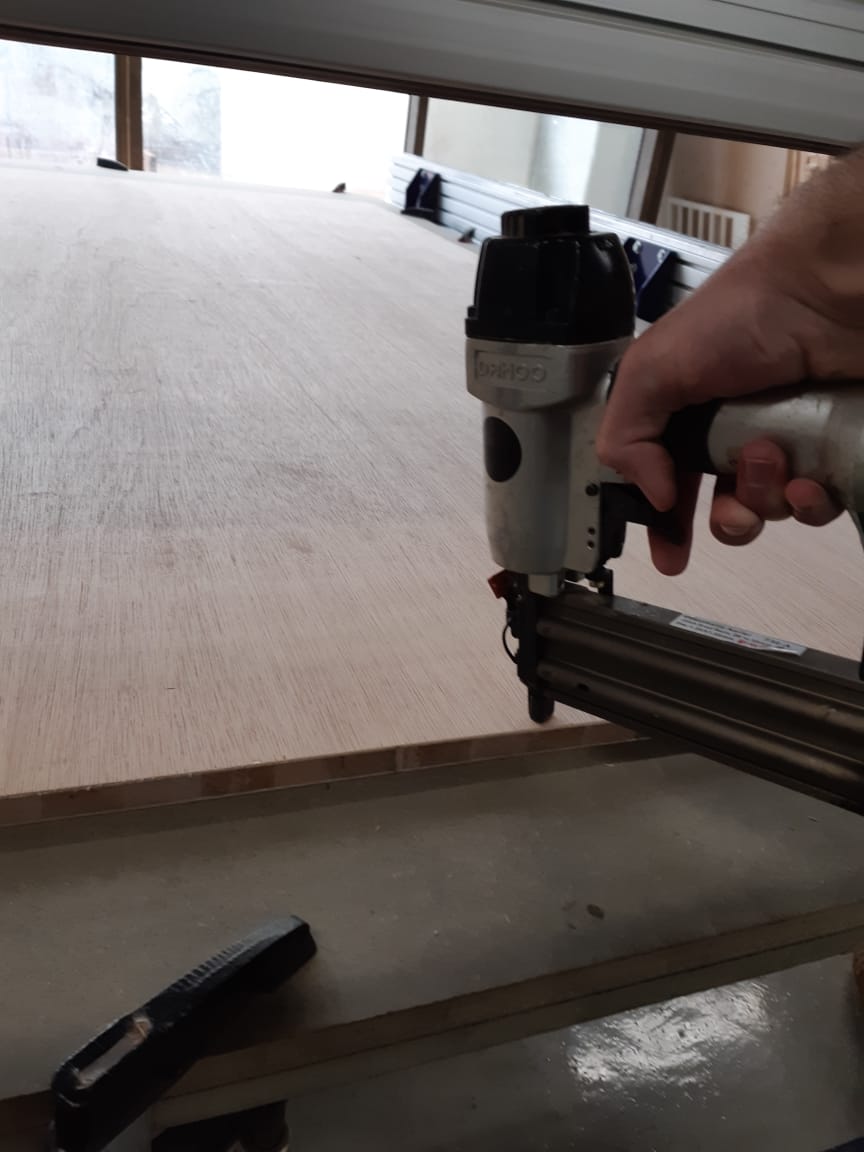
We have to place the board and fasten it to the bed. To do so, I used air-gun to shoot bolts into the edges of the board.
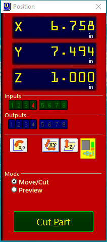
Second thing is to define zero axises. On the Shopbot, click the XY button then control the endmill in the X and Y directions. Moving it to the very cornter of the board (or you can leave 1 cm clearnece to ensure that the mill wont hit the bolts) we order the machine to zero the axises there from the commanding consol.
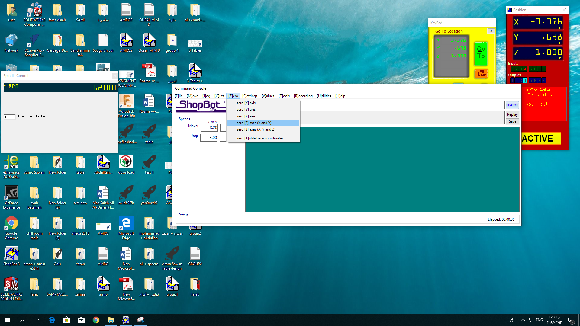
Now to zero the Z axis, we have to create a small circuit. The first node is a clipper, we attach it to the mill. The second node is a metal plate we palce under the mill.
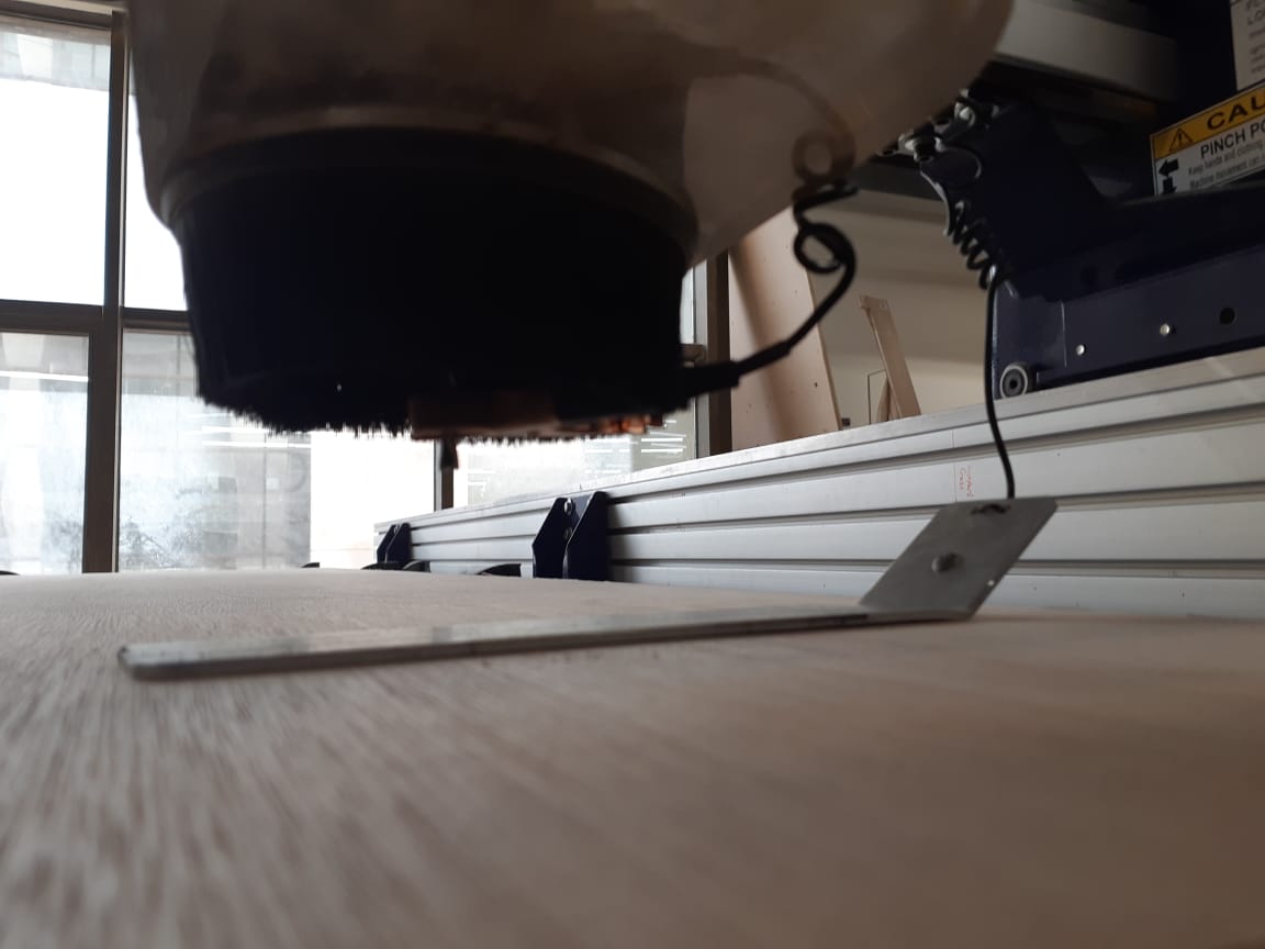
On clicking on the Z button on Shopbot, the mill will emerge down until it touches the plate, and that's when the circuit is connected. A signal is sent to the software telling it that at this height, the tool is above the zero plane in the amount of the plate's thickness.
Now the machine is ready to start cutting, we click on Cut, Choose the G-code we saved, then click start. A window will appear telling us to press the start button on the machine's controller, this button will start the spindle's rotation.
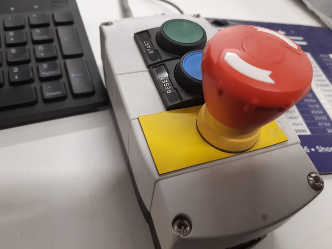
Note that when the CNC starts cutting, you wont be able to do anything on the computer except pausing or stopping the machine. (Click space to pause and the stop button to end)
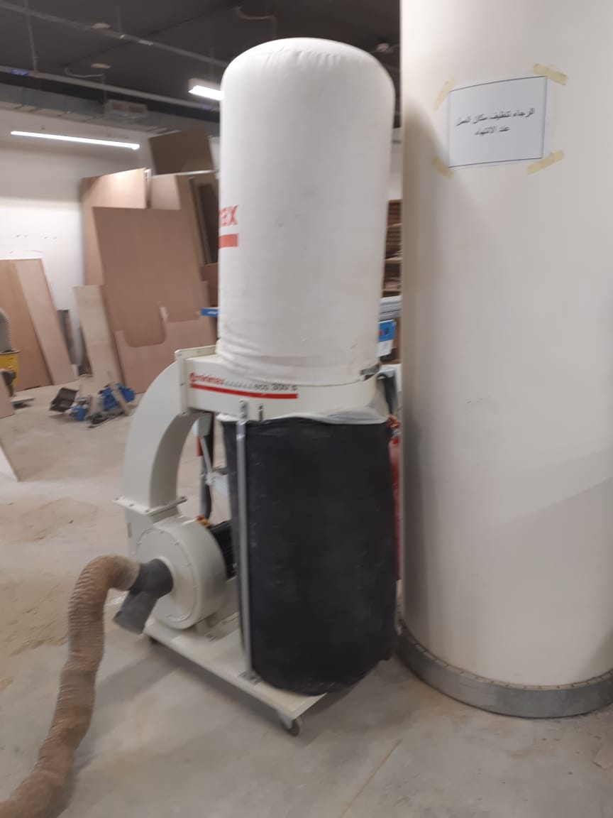
Before starting the job, make sure the vacuum cleaner is connected and ready to function. Run it when starting the job.
The machine finished the Job succesfully, but some issues occured and needed fixing...
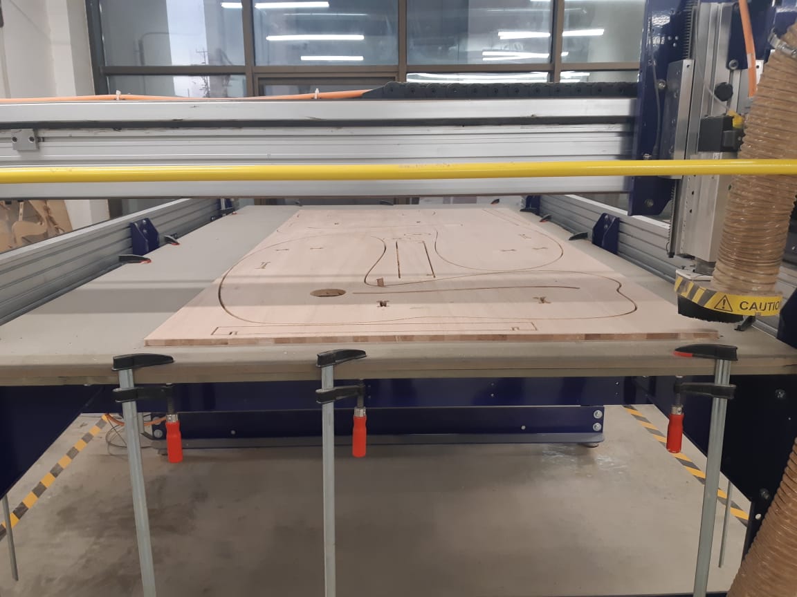
Problems:
First problem happened because I did not add tabs to my job. The big sized parts survived slipping, but the small parts did not. The two small disks got corrupted and were not cut in a perfect round shape. So I had to rework them with the second board.
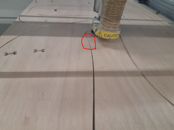
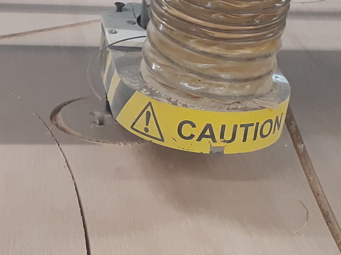
It is visible in the pictures that the cut space does not seem uniformal along the line, rather the space is getting narrower, yet wider on the opposite side. That's because the part slipped during the cutting and started moving from its position while the mill is cutting.
Another problem was the cavities in the Latte Woodboard. For the parts I made with the first board, those cavities wont have a significant effect.
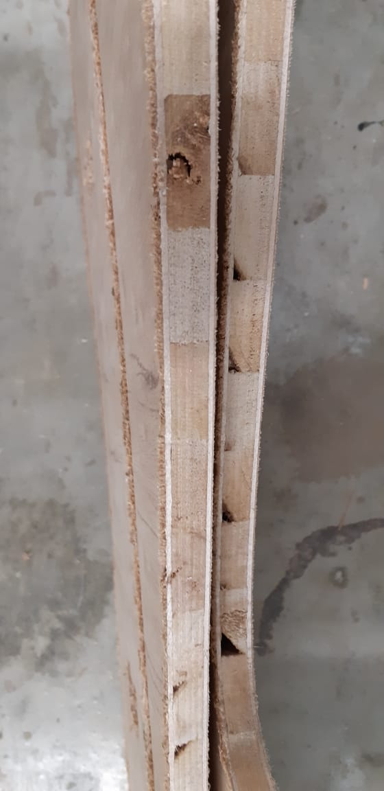
But for the second board, there will be a living hinge. Hence, the cut parts wont be wide enough to neglect the cavities. So I decided that for the next board, I will use Plywood instead.
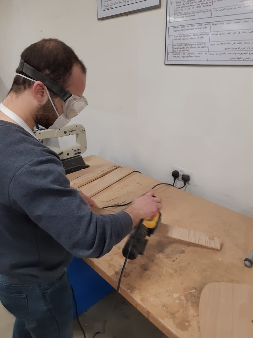
The last problem was the roughness of the cut surface. Those rough edges ocured due to the speed of rotation, the characteristic of the material and the quality of the endmill. But anyhow, they needed sanding to smoothen the surface and to fit inside each others in the assemble.
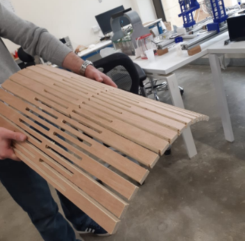
Using plywood, the living hinge was created succesfully:
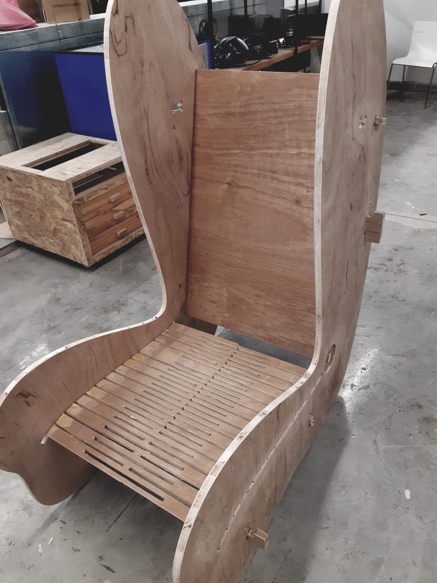
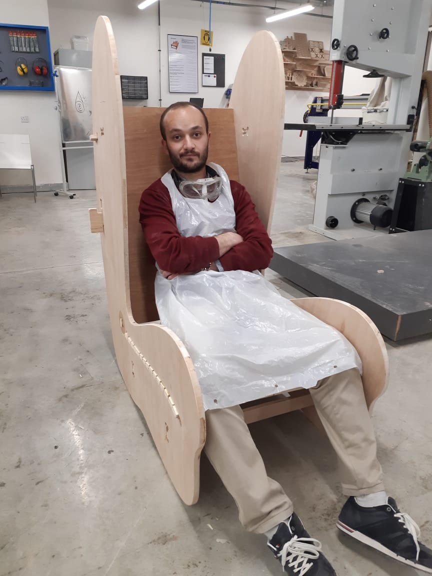
And finally, after a lot of finishing and sanding processes, the chair was assembled and tested
The seat is super comfy, with the adjutable back functioning properly.
---
