


Fusion 360
I have used this software to design a magnets slider, for the application covered in this video.
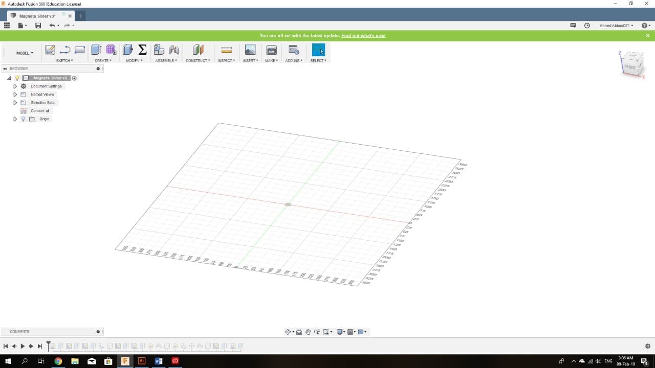
The interface of Fusion 360 is simple and user friendly. Refer to the picture below to see how the new window looks like. Notice the symbol Σ in the tool bar; this tool will be used for creating a parametric design.
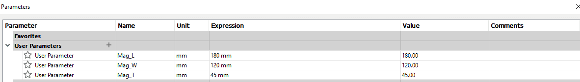
Clicking on it, will pop up the parameters table. Here we add the parameters that are going to restrict our design. In my case, the dimensions of the magnets are the restrictions because those will depend on the magnets available in the market. So I named three parameters for the length, width and thickness.
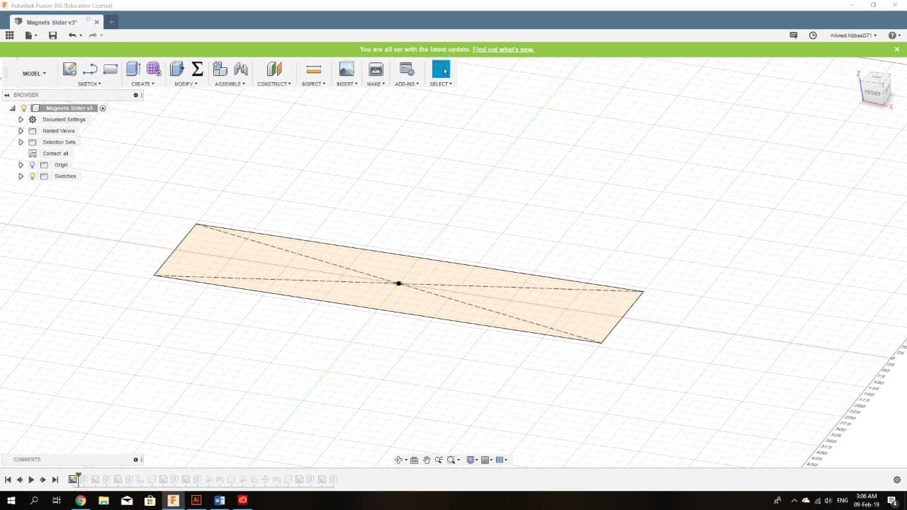
Now to the sketching, we select the plane and click on the sketching tool. Then start with our sketch.
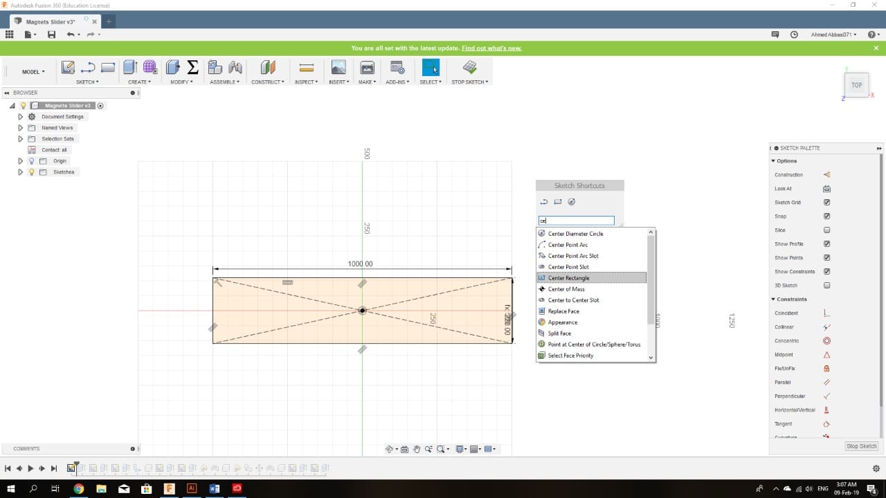
To sketch anything, click S on your keyboard, then select the shape you want to sketch. (see the sketch table in the picture below)
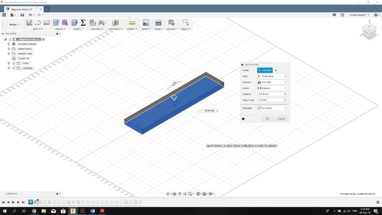
After finishing the sketch, click stop sketching. Now for extruding the sketch, click create, and select the distance.
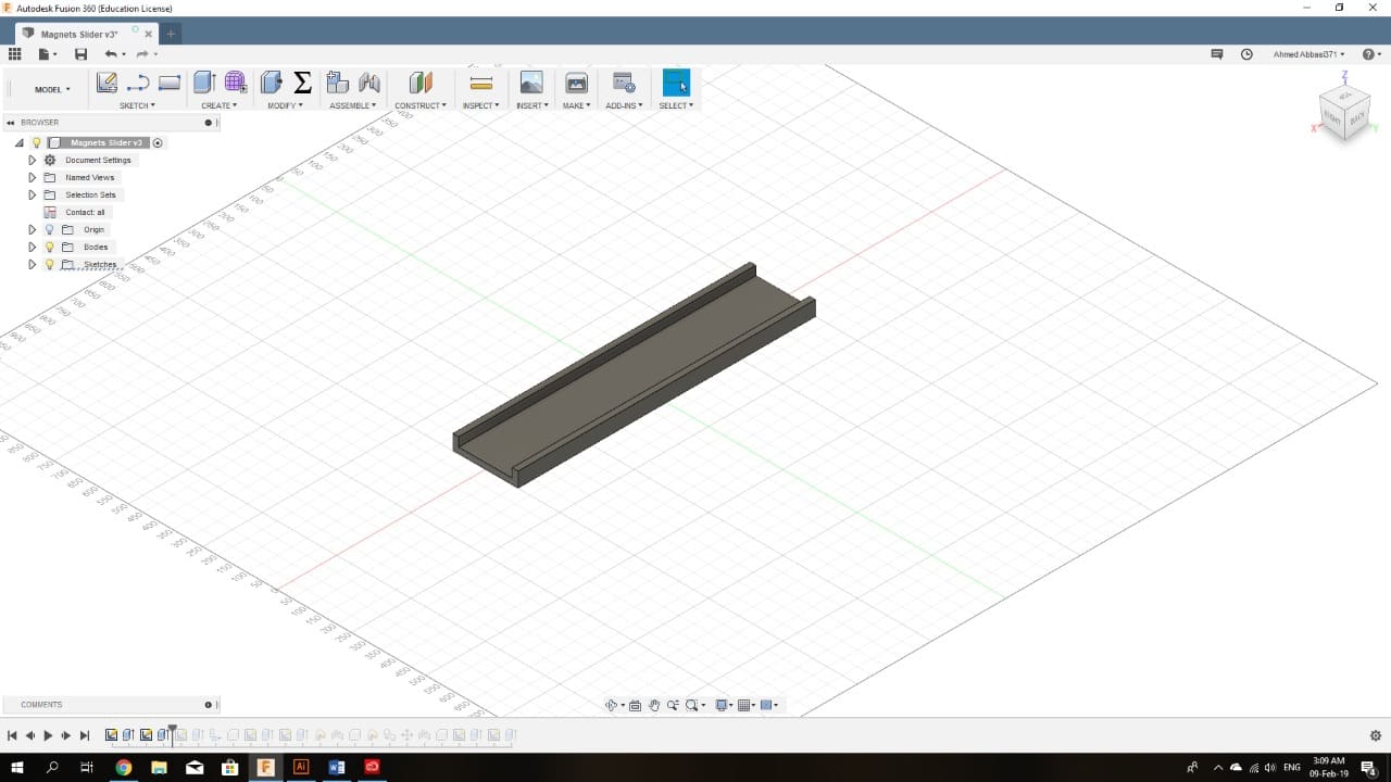
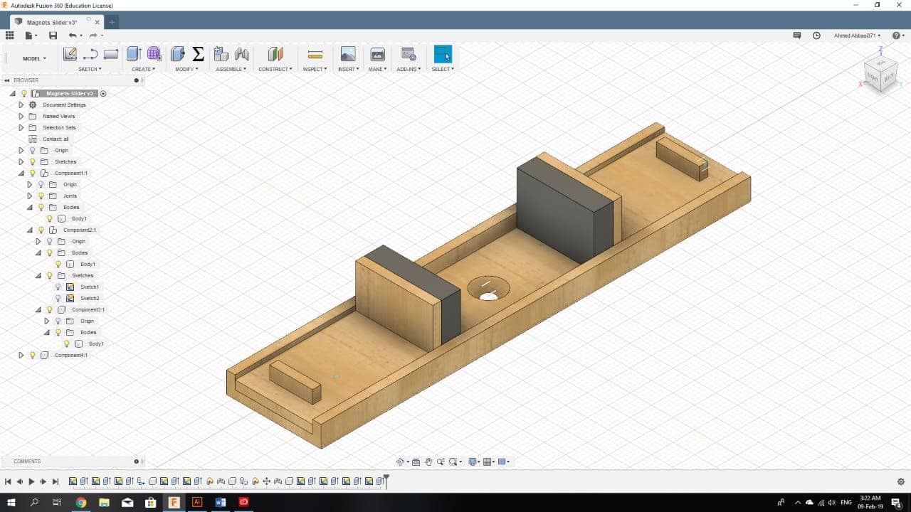
Now we have a body:

To create a cut in the body, follow the same steps for creating a body (select a plane, sketch, click create) after clicking create, drag the extrusion into the original body; this will cause the command to remove the overlapped volume from the original body.
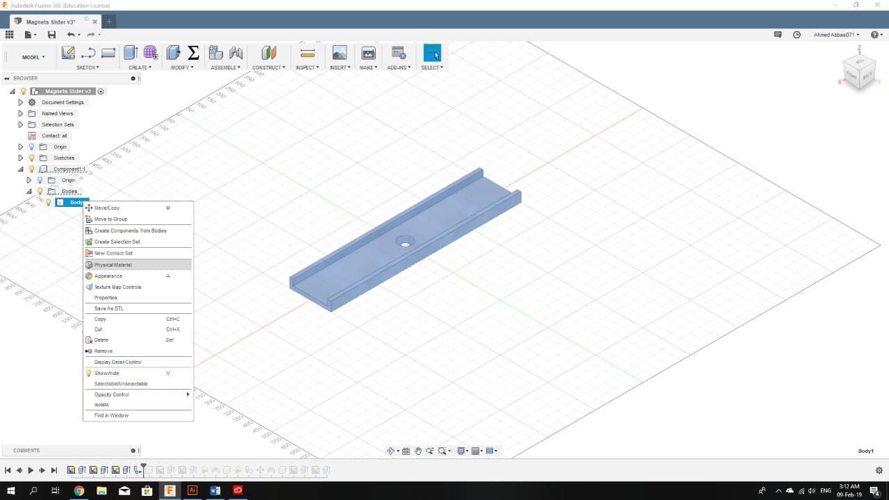
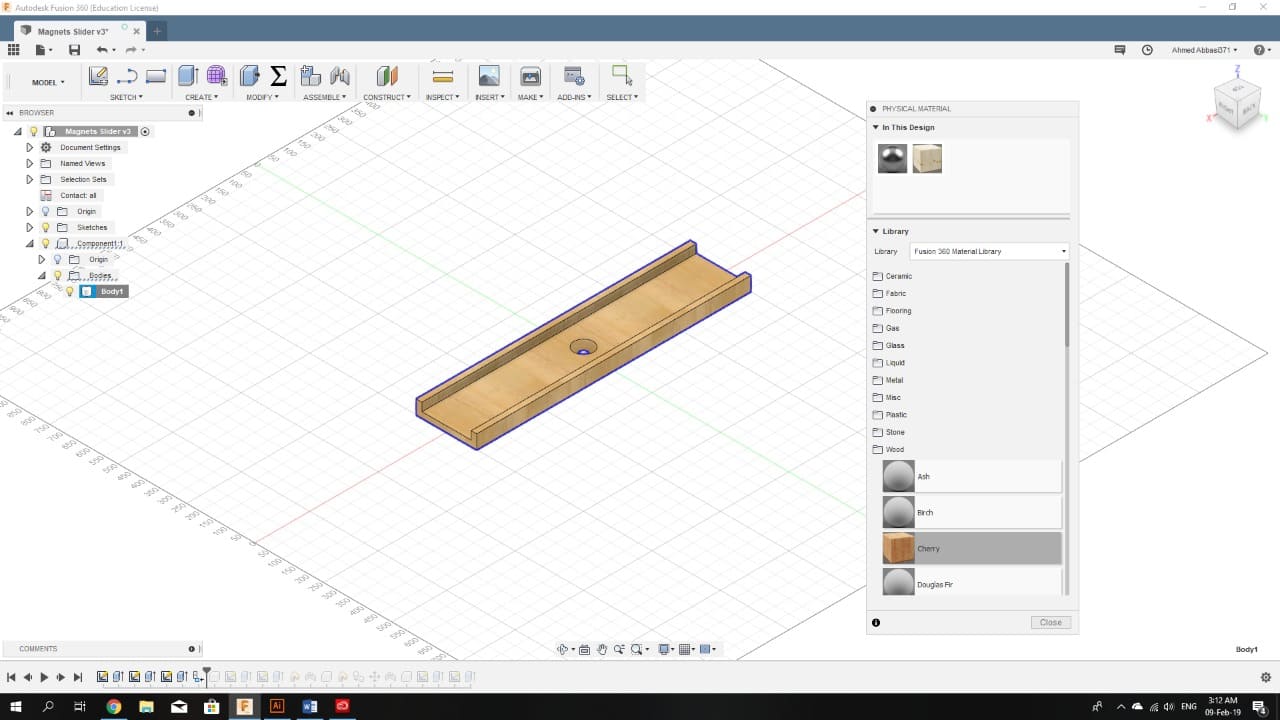
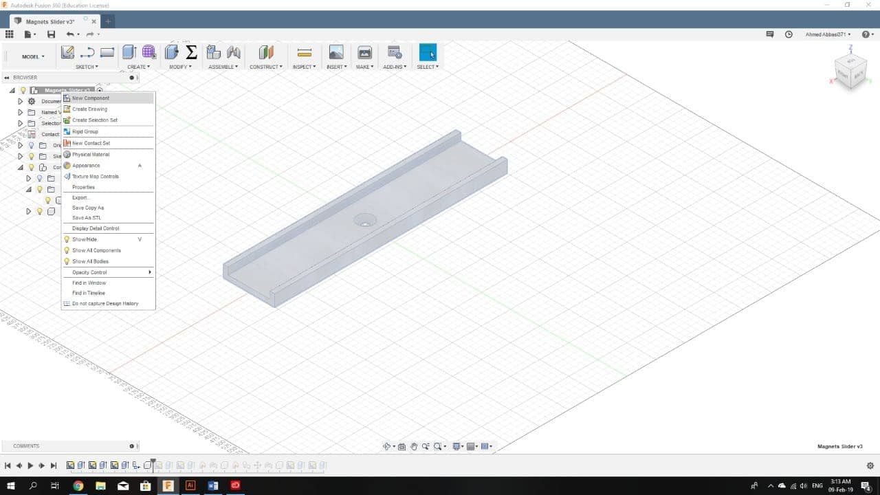
In order to select a material to be assigned for the body, right click on the desired body from the list on the left side of the window, then click Physical Material and select on from the options available.
The first component of the system is complete, now for the next component, right click on the original file from the list on the left and select New Component.
Following the same steps, we create different components:
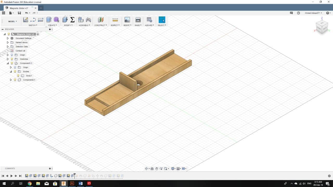
After designing all of the components, we start with the assembly.
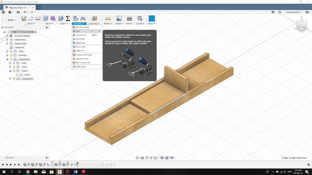
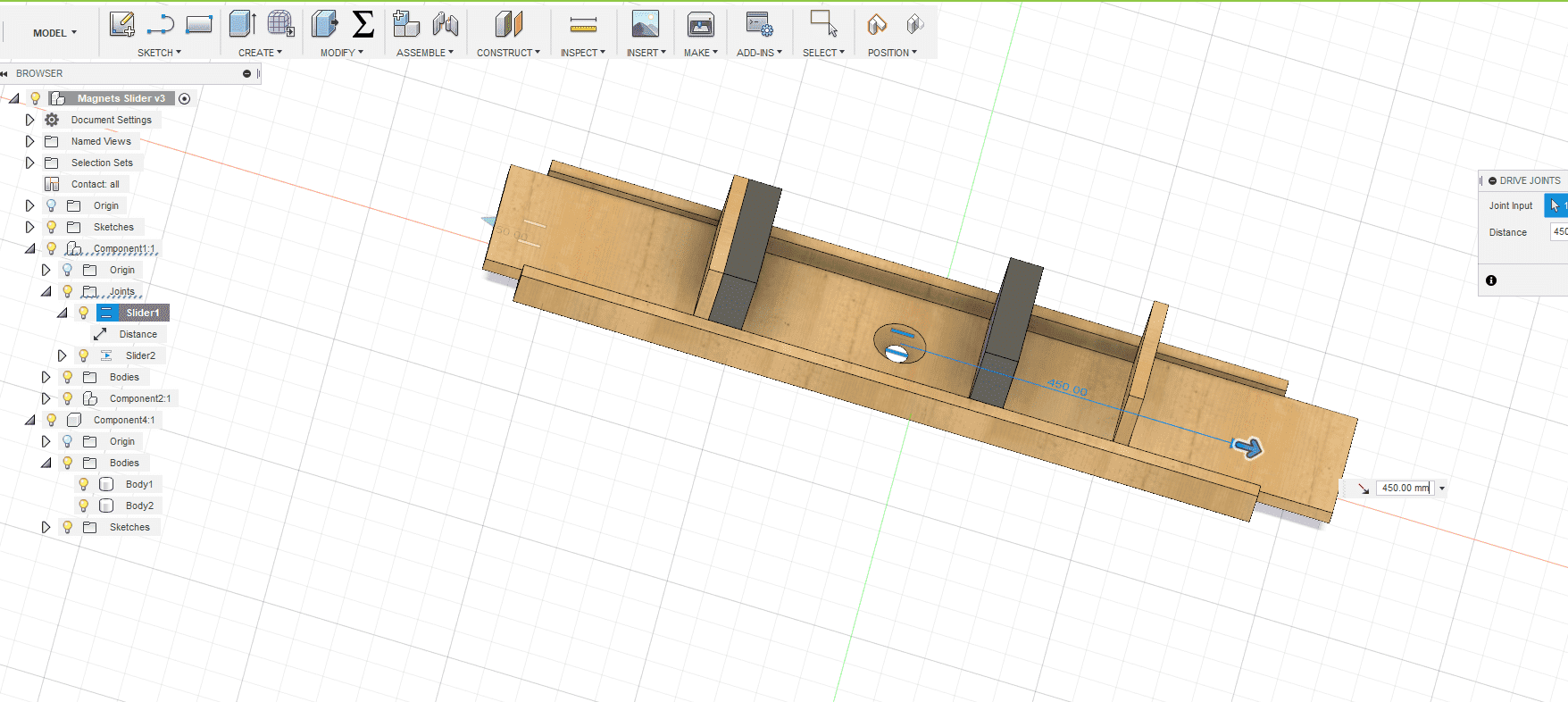
I want to make a slider joint, so I selected the type of the joint I want to create first, then selected the surfaces that I want to be sliding on each other and finally selected the sliding axis.
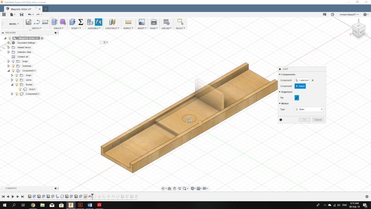
Repeating this for all the components depending on how I want them in relation to each another. I had my complete system with a demonstration of the sliding mechanism:
SolidWorks
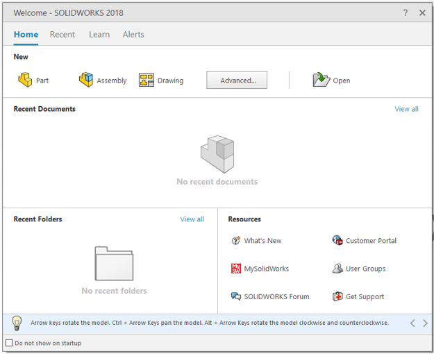
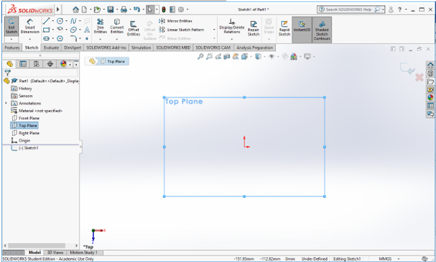
When starting SolidWorks, you have to select whether you want to create a drawing, a part, or an assembly. I will start with the part creation as it is the most used one. The assembly is basically assembling multiple parts together, so we will go to that after finishing the part creation. And the drawing is creating a 2D sketch. If you can create a 3D part, you will easily be able to create a 2D sketch. Hence, I will skip that.
On the part creation window, you can see the tools in the upper bar divided into tabs, we will start with the sketch tab as from the sketch we can extrude a body.
On the left we have a list of the components of our design. The standard components are always there, and from them we will pick a plane to draw our sketch.
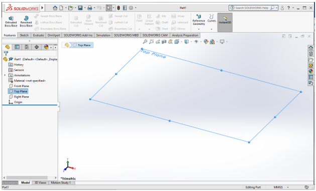
From the Sketch tab, click sketch while the plane or surface is selected and the screen will rotate automatically to be normal to the sketching surface.
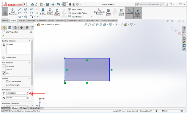
You can use the tools visible (line/rectangle/circle… etc) by selecting them, then using the mouse sketching them, and finally selecting their dimensions if needed.
I started with plotting a rectangle. then by clicking on one of its edges, I can control its dimensions from the left section.
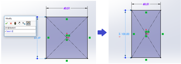
But before we continue with sketching, I want to define some parameters first to make some critical dimensions of my design easier to control. (to exit the sketch, click on the X button in the right top corner). From the left section, right click on Equations then choose Manage Equations. There, you can add and edit variables. I have added 3 parameters as you can see.
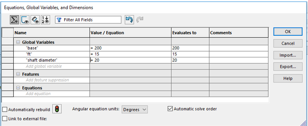
As you can see, I have already added a parameter named “base” with 200 mm dimensional value.
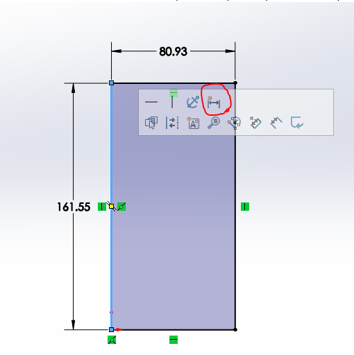
Back to the sketch… I can click on the line and select Auto Insert Dimension. Then click on the dimension again and a modify window will show. There, I can insert the parameter I previously defined and maybe with an equation.
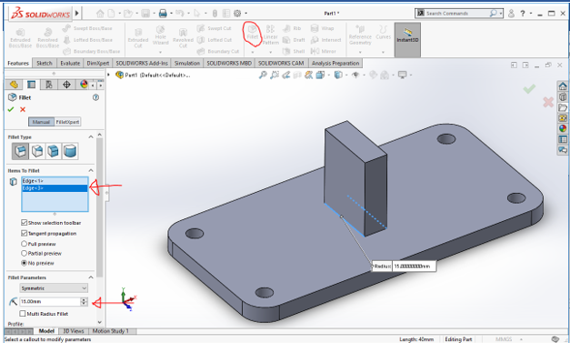
Another sketching tool is called fillet, click it then select the corners you want to apply it to and select the radius.

After finishing the sketch to be extruded, go to feature tab, select the sketch from the left section then click extrude. Control the height.
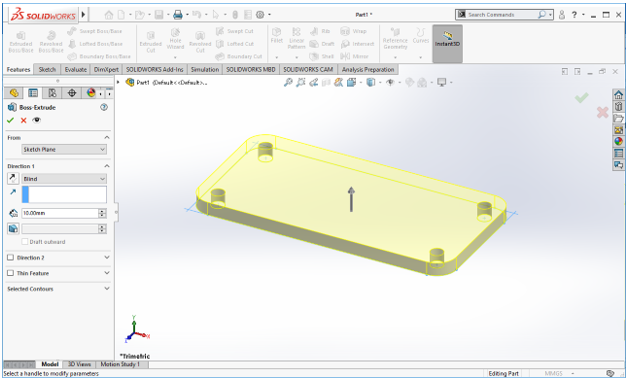
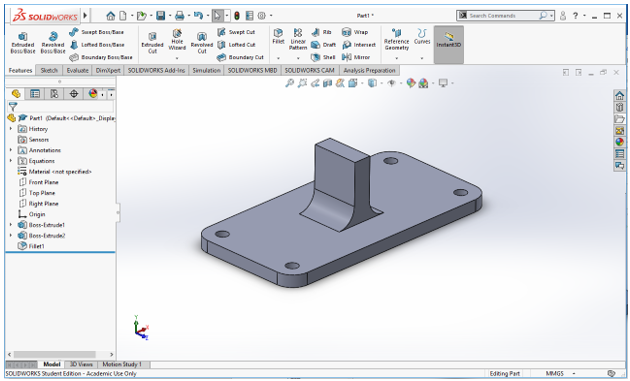
After clicking on the check sign, the body will be created and appear in grey colour.
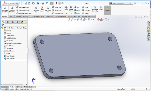
We can now sketch something on the surface of this body and then extrude it.
We can add fillets the same way we did in the sketch, by selecting the edges and the radius:
Note: remember that you can always edit any component from the menu on the left section, but make sure that the things you created after the component do not depend on it or they will be corrupted.
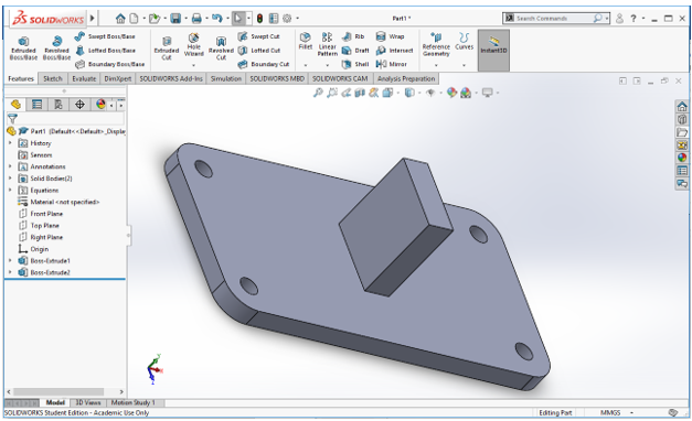
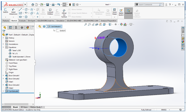
Now I want to create a hole in my design.
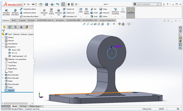
Just as creating a body, sketch first then choose Extruded Cut
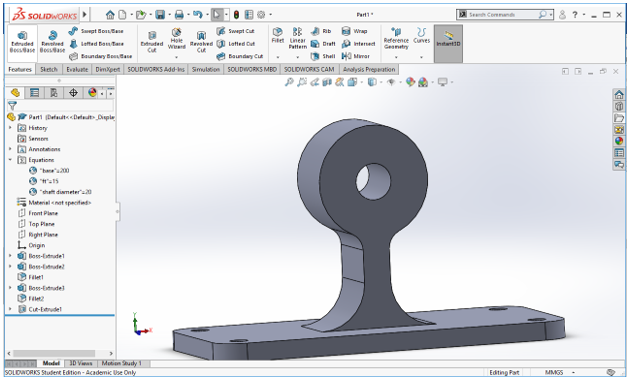
Let's now to try the parameters, go again to Equations>Manage equations. And change any of the variables then check the Auto Rebuild box and click OK.
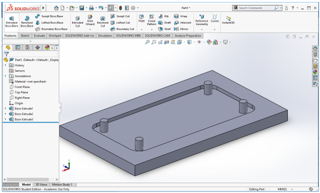
Now the basics of creating a part were covered, we can move to the assembly. But first I have to create another quick body to assemble it with this one.
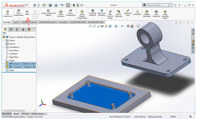
Now we open a new design and select assembly. Then we select the folder that contains the parts we will be using.
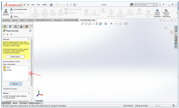
Choose a part by a double click on it to place it on the working screen.
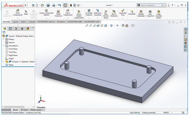
To add the next component, click on Insert Component in the top left.
Add the body then select both the surfaces you want together and click Mate.
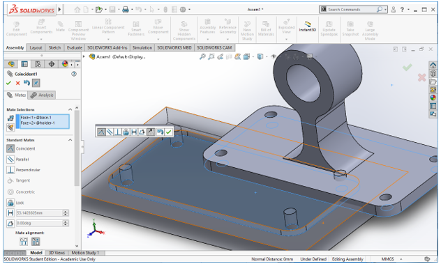
Now the two surfaces are facing each other. Click the check sign to create the next restriction.
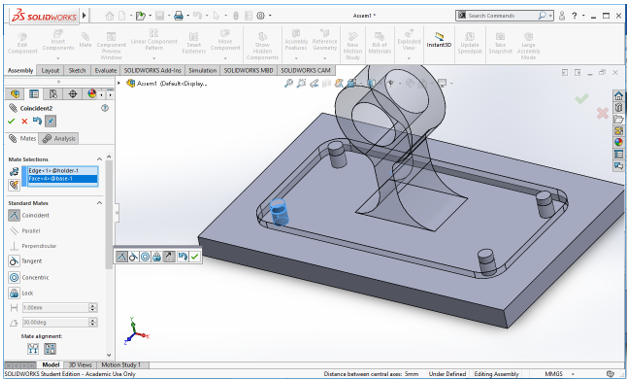
I selected the hole and the bolt in the base so they would be inserted in each other.
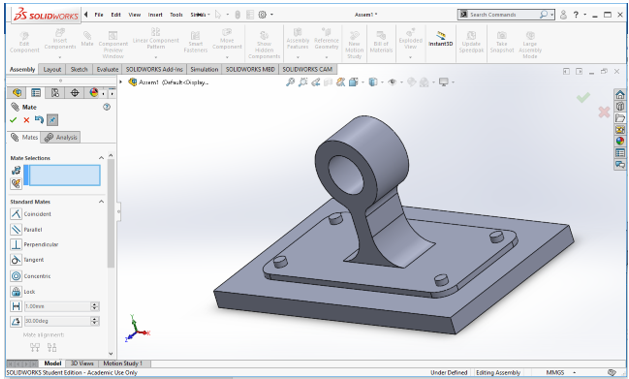
Now the components are assembled to form a complete structure.
Illustrator
I have used this software to illustrate the control systems I am to use in my project. First system would be to scan the paper, translate the image into text, send it to the audio speaker to read it (possibly using Google Translate for this objective). The second system would be to control turning the pages.
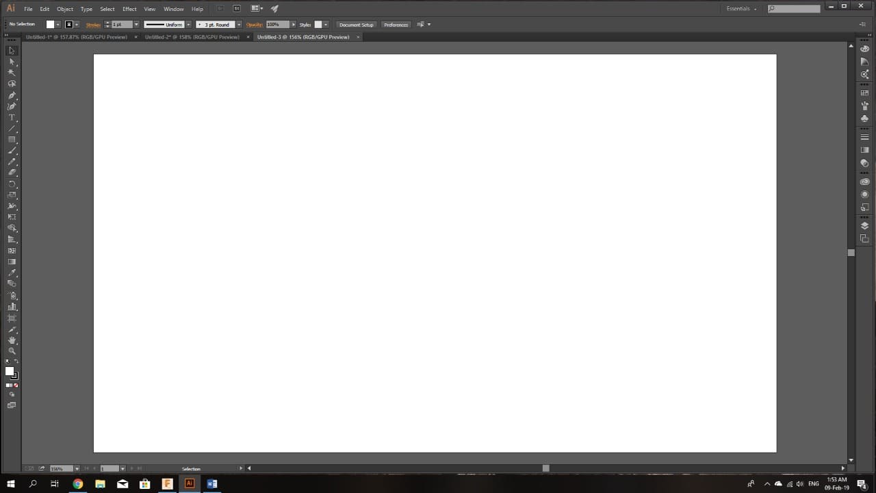
The following picture shows Illustrator interface:
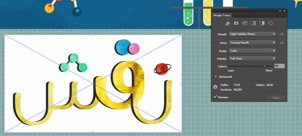
A very useful tool in illustrator, (specially when using the laser cutter) is the image tracing; it converts the image from pixels to vectors.

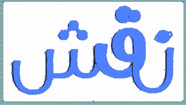
As we see, the original picture is pixilated when you zoom in. but when we turn it into vectors the zoo, in will look like this:

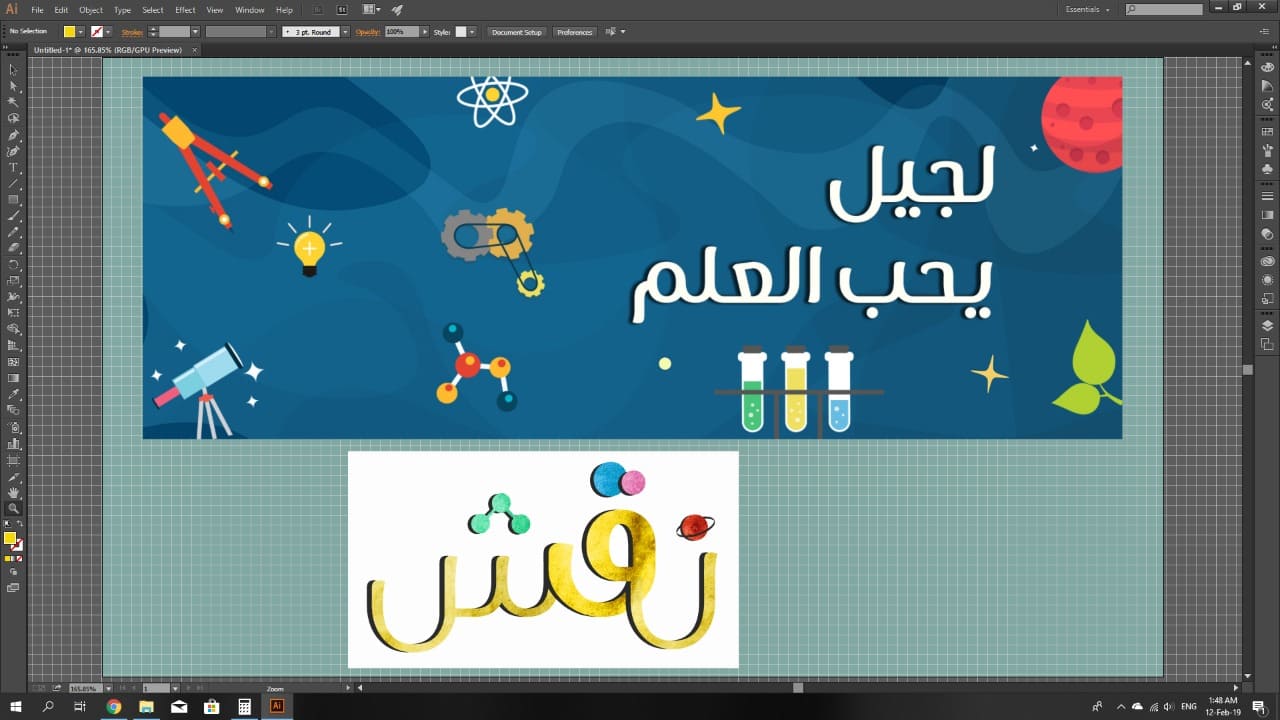
First of all, the pictures I want to work on are to be added.
I want to make a sticker of the logo of the initiative I work on called Naqsh (an Arabic word that means Engraving). And I want to add the logo to a scientific themed background as this is the field of the initiative.
We trace the images to get them in vectors.
Click on Expand, to give you ability to control small portions of the pictures.
After expanding, it will be easy to remove the white background.

From the theme picture, remove the letters the same way like the background. Then fill the empty spaces left by spreading the patterns using the pen tool.
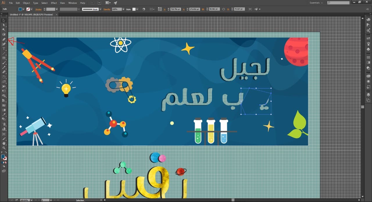
Place the logo in front of the background and arrange the clip arts as desired.

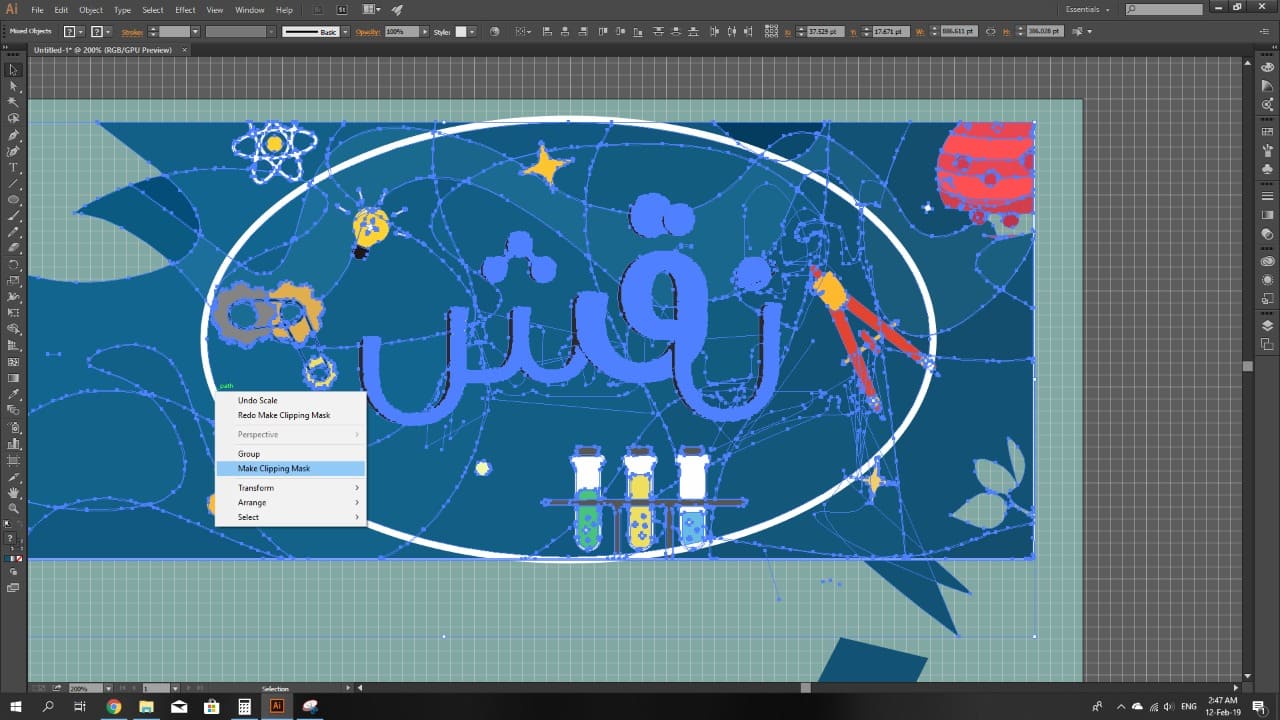
Add an eclipse the surround the desired area then by right click and clicking the masking option, everything outside the frame of the eclipse would be deleted.
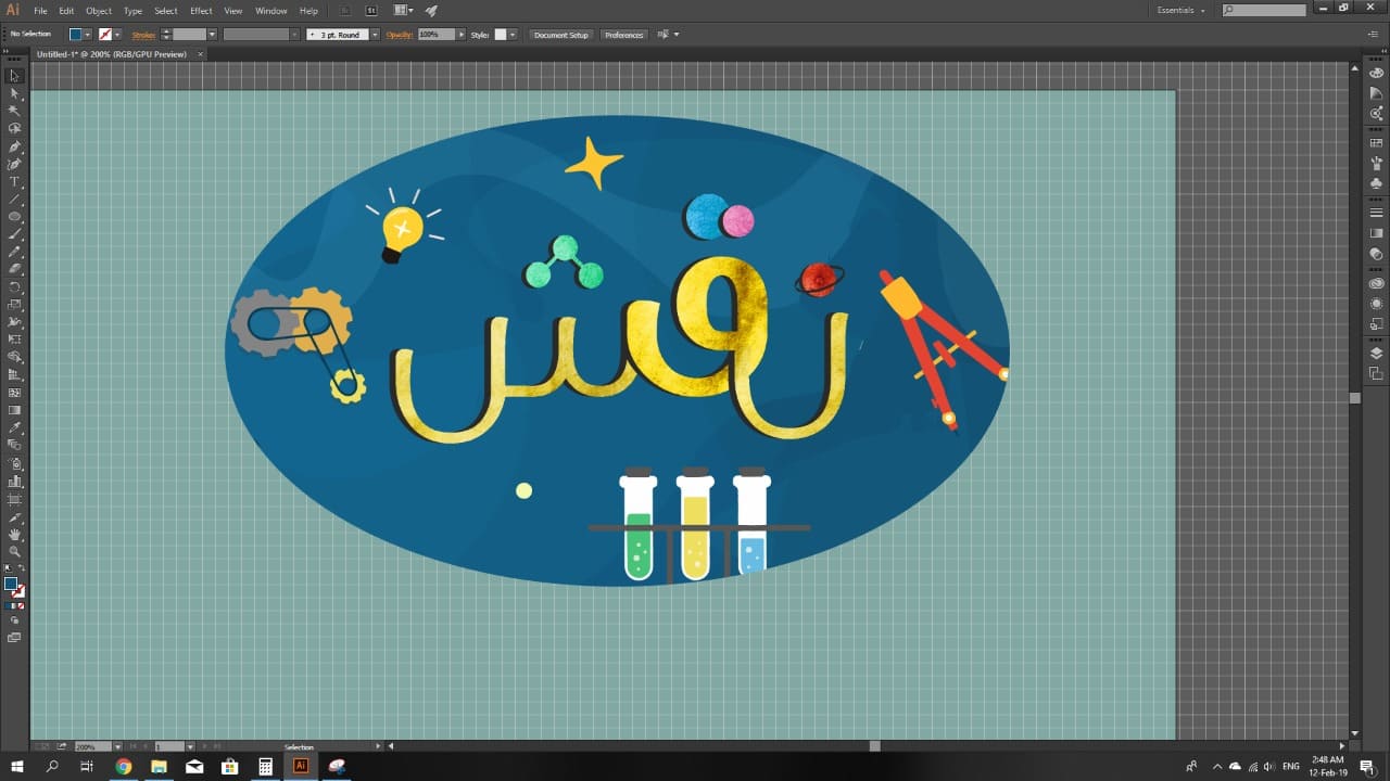
Finally, the logo sticker is prepared, and was saved as PNG file to be printed next week using the vinyl cutter.
---
