
In this process I had to design a couple of boards. I’ve been using Eagle and completed my learning (still in process, of course) with some tutorials online.
 right click to download the svg above - my version of the hello board in the easel/carvey ready mode
This assignement was about the re-design of the hello board to which I added a button and a led. I started by reproducing the entire schematics on the schematic view.
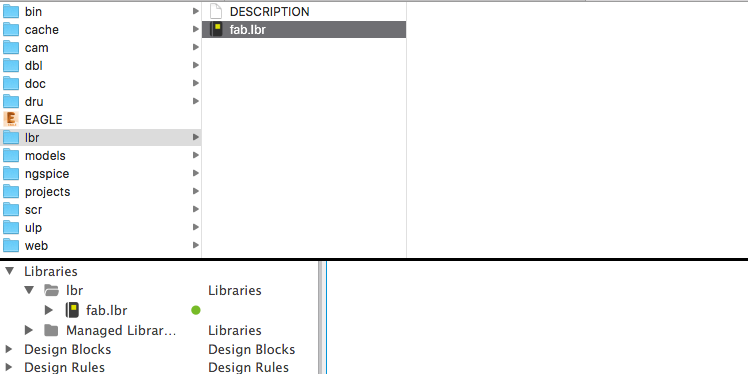
In this specific case I also had to import the fab library of components:
 Right-click to download the svg above - my version of the hello board in the easel/carvey ready mode
After that, I added the new components.
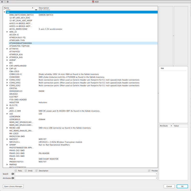 How to add new components to the schematic
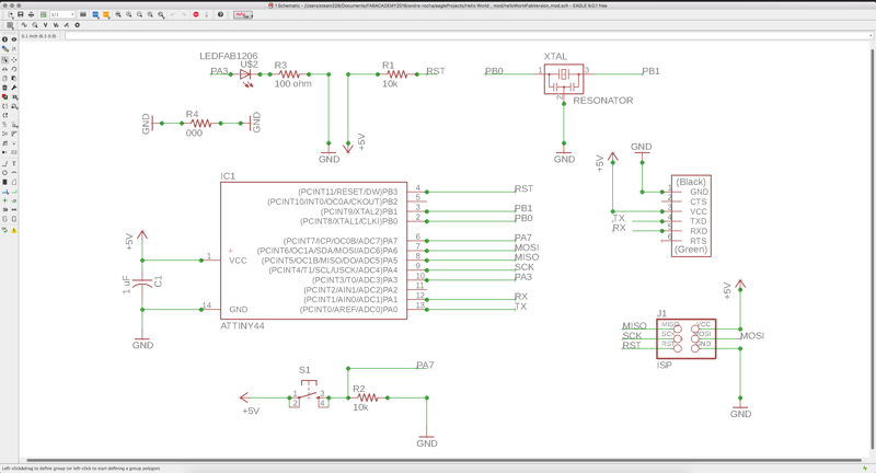 Final result - schematic
 A mess....indeed.
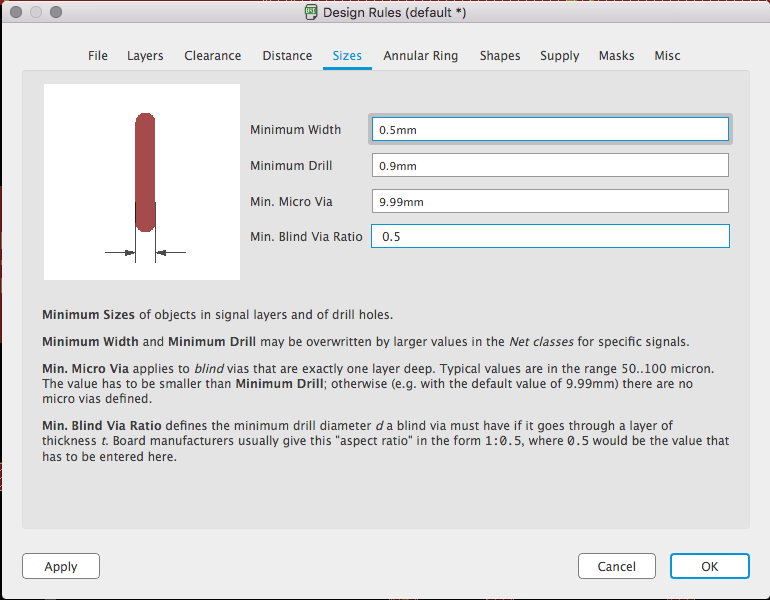
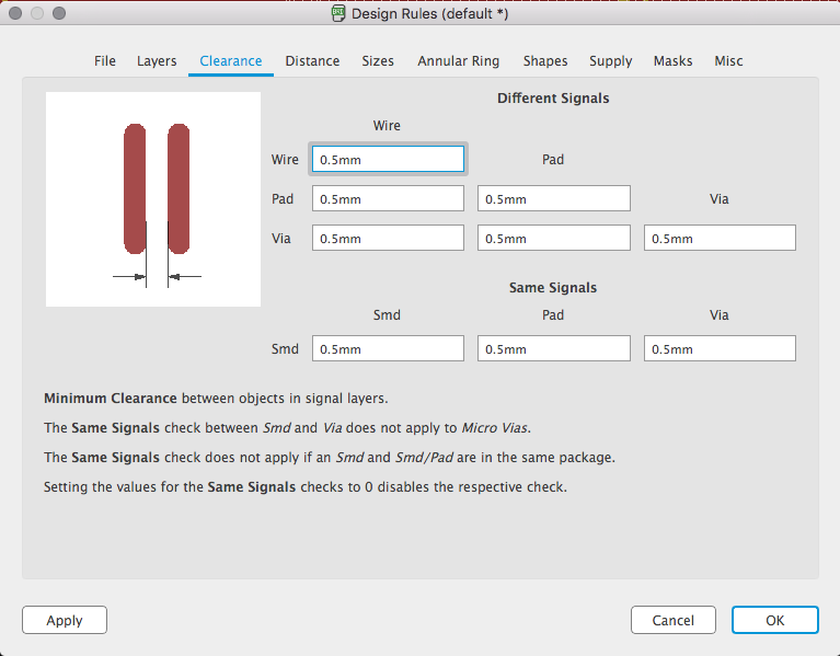
When finished, I jumped into the board view, where all the components were a mess waiting for a bit of “graphic design”. As I don’t know much about electronics, one of the first things I had more dificulty doing was defining the rules. Those rules depend mostly from the way you expect to produce the board. In this case it was a milled prototype so I couldn't expect fine clearances and I had to play defense. I was expecting to use a 0.4 mm mill and a 0.8 mill to cut the board out.
After these steps, the game begins because you will have to fit everything into one side of the board. I usually try to place all the components with the yellow fin link lines pointing at the other end. After that you can trigger auto-route once just to have an idea of what is the proposal. Maybe you’ll be surprised. Most of the times you don’t.
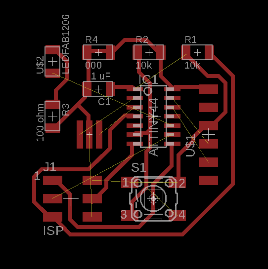 An autoroute result, still a lot to solve ...
So, just start throwing lines. Remember to avoid 90º corners and to be aware of the rules you defined. This is a challenging and engaging iterative process. I think my boards will always get better with training.
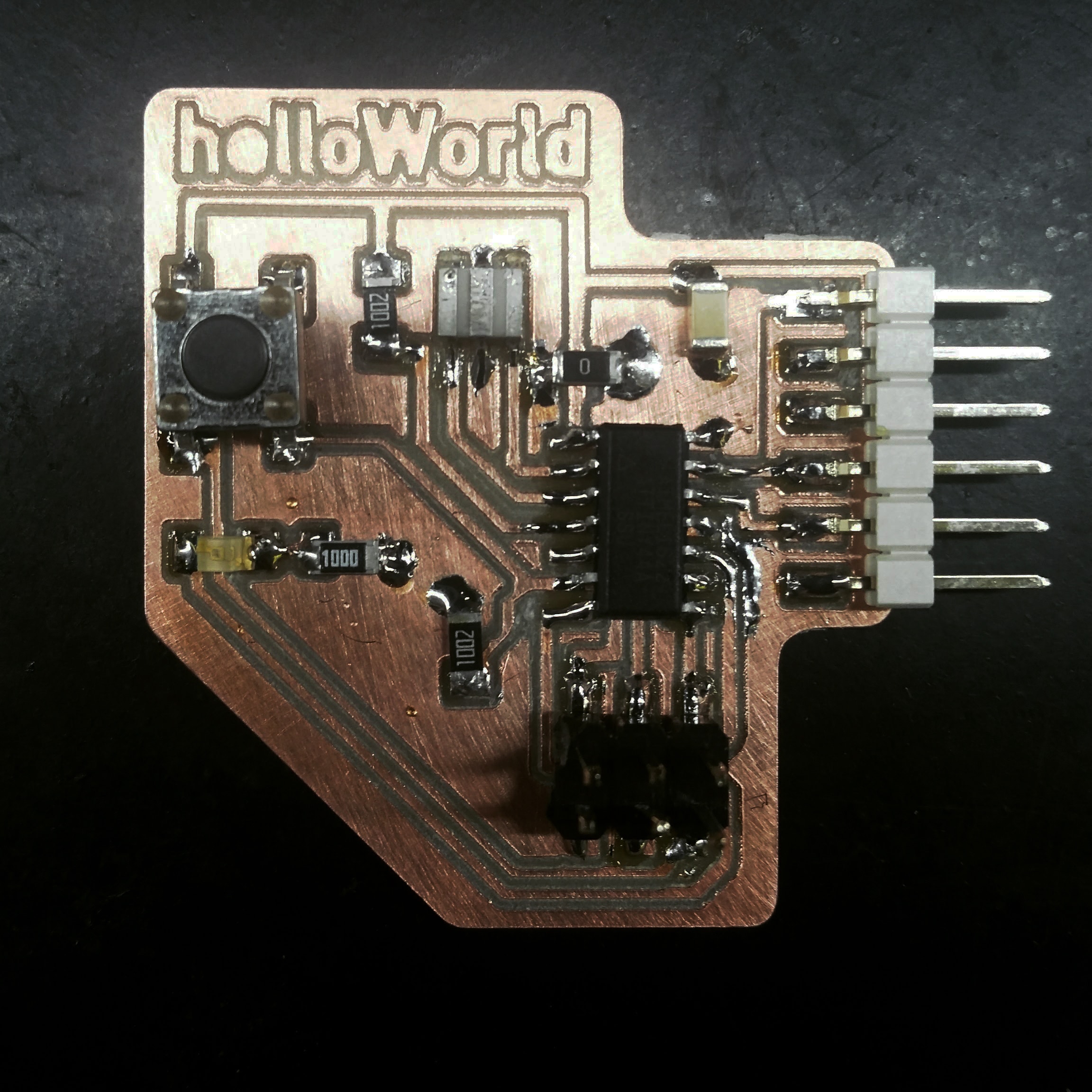
Programming it The result.