
In order to setup everything I started by looking for a good open source possibility that would allow me to:
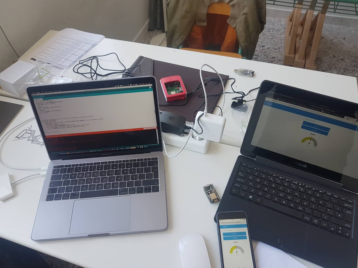 first node-red dashboard screens at Tzoumakers
Since the goal here is to set up a standalone distributed solution the server and main app will be hosted locally in a raspberry pi computer configured for that purpose.
Also, we decided to use Node-Red (a visual NodeJs implementation), easy for anyone to work with and customize.
https://core-electronics.com.au/tutorials/raspberry-pi-zerow-headless-wifi-setup.html
https://www.raspberrypi.org/documentation/remote-access/ssh/unix.md
            sudo apt-get update
            sudo apt-get upgrade
            bash <(curl -sL https:/raw.githubusercontent.com/node-red/raspbian-deb-package/master/resources/update-nodejs-and-nodered)
            sudo systemctl enable nodered.service
sudo apt-get install Mosquittosome instructions on how to test here: https://www.instructables.com/id/Installing-MQTT-BrokerMosquitto-on-Raspberry-Pi/
Security: manage permissions on node-red tutorial - https://www.youtube.com/watch?v=GeN7g4bdHiM
A very easy way to get things done in a practical and comprehensible prototype is to use node-red dashboard.
This enables us to use very simple UI modules, both for input and output.
Maybe your intervention in the design of that very same UI won’t be the one you dreamed of and won’t go further than color changes, but it is for sure very handy.

In the upper right menu of the Node-Red Interface look for "manage pallete" option. Then choose the install tab and search for "node-red-dashboard"
There your go. After a couple of seconds your node-red interface will have all the dashboards node modules available
GROUU is about distributed modules that ultimately send and receive data from a local raspberry pi server.
Even if later I will want to add a proper web app I believe that a distributed system should retain its “intelligence” on local servers and that those should be accessible for different levels of users, even when there is no internet connection.
To build this test I injected a NodeMCU (ESP12 dev board) with customised version of a home automation code I got from a previous version of BHOnofre (BH Firmware)[github.com] (a project run by Bruno Horta, a very well known Portuguese Maker).
I found it very useful and easy to adapt and I hope to find time to upgrade my basic firmware after studying his new more complex versions.
This specific uses a couple of very handy Arduino Libraries. These are the main ones:
Having this set it is important to also configure correctly the variables and constant values that will be determinant for the connections and future organisation.
After some experiences I decided to organize a modular header with a comprehensible naming for each device:
const String Instalation = "Tzoumakers"; //Where is it?
          const String IDCODE = "1"; //Number your Device
          const String TYPE = "Nursery"; //choose type
          const String Host = "Grouu" + Instalation + TYPE + IDCODE; //just change if it is not grouu
          const char * OTA_PASSWORD  = "YourPasswordHere";
          const String MQTT_LOG = "system/log"+ Host;
          const String MQTT_SYSTEM_CONTROL_TOPIC = "system/set/"+ Host;
The resulting construction of the Host name would be something like GrouuTzoumakersNursery1
The rest of the code used in the first implementation is available on the GROUU code folder of this the repository GROUU/ARDUINO/GROUU_V1/tzoumakers/grouu-nurse
Very simple results can be achieved just by publishing a variable over MQTT, receiving its values in the Node-Red app MQTT in node and publishing it directly to a node-red real-time graph module. It’s easy simple and efective.

As you can see in the example, the same is true by just dragging and dropping a button module and have it send an MQTT string or boolean which is being expected by a specific ESP Module.
The screen will tell you if the MQTT connections are working, which is the same to say that the green connected sign underneath will tell if MQTT connection between both devices and the broker app is happening and if it is ready to send or receive values.
This doesn’t mean that if the channel has a wrong capital letter or other kind of mistake in the name, the green sign won’t be on and you’ll have a hard time figuring out the error.
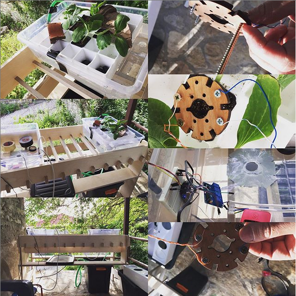
The first implementation I’ve done for the work relating to this week was at a workshop where I participated and that allowed me to partially develop most of my final project which also has correspondence in most of the weekly challenges.
In this case you are expecting the application to allow manual control over the valves and motor that fills and empties the two planting tidal trays we added to our design.
In order to develop further automation features we also needed to see the level of moisture on the soil (or different) substrate on the small vases where the seeds are sprouting. (See input devices week)
This will send through the ESP12 (for this prototype the nodeMCU dev board)
These needs resulted in the configuration of a couple of channels:
          //valves
          const String MQTT_VALVE_ONE_TOPIC = Host+ "/valve/one/set";
          const String MQTT_VALVE_TWO_TOPIC = Host+ "/valve/two/set";
          const String MQTT_VALVE_THREE_TOPIC = Host+ "/valve/three/set";
          const String MQTT_VALVE_FOUR_TOPIC = Host+ "/valve/four/set";

          const String MQTT_VALVE_ONE_STATE_TOPIC = Host+ "/valve/one";
          const String MQTT_VALVE_TWO_STATE_TOPIC = Host+ "/valve/two";
          const String MQTT_VALVE_THREE_STATE_TOPIC = Host+ "/valve/three";
          const String MQTT_VALVE_FOUR_STATE_TOPIC = Host+ "/valve/four";

          //pumps
          const String MQTT_PUMP_ONE_TOPIC = Host+ "/pump/one/set";
          const String MQTT_PUMP_ONE_STATE_TOPIC = Host+ "/pump/one";

          //sensors
          const String MQTT_MS1 = Host + "/sensor/MS1";
          const String MQTT_MS2 = Host + "/sensor/MS2";
          const String MQTT_MS3 = Host + "/sensor/MS3";
          const String MQTT_MS4 = Host + "/sensor/MS4";
This kind of organisation is essential. The latest version of the implementation was not this rich because we missed some materials the made us reduce the solution to a proof of concept of the nursery system, but, the illustration of the modularity of a possible solution is much more clear through this version, to which we will get back in the final project version.
like said before, easy and quick are the words for Node-Red.
We easily created an app that received values and allowed us to manually control some of the physical features of our Nursery.
Next steps will be to add automation in order to relate inputs and outputs and automate plant sprouting easily.


Using Topics and if/else functions: NODE-RED FOR DUMMIES—TUTORIAL 06—CONDITIONAL COMPARE TWO NUMBERS BASIC BEGINNERS FUNDAMENTAL - YouTube
Adding password to Node-Red (very important in case of remote access)
#fabacademy