Computer-aided design
Assignments
Model (raster, vector, 2D, 3D, render, animate, simulate, ...) a possible final project, and post it on your class page
Here is my list this week:
- Give a try to 2D and 3D tools and select a short list of tools I would like to give a try. Those tools are: GIMP, Inkscape, Sketchup, FreeCad, Antimony and Blender. I deliberately put aside tools that do not run on Linux and/or relies on commercial licences or any kind of subscription.
- Evaluate GIMP tool (2D- raster): my goal is, starting with a high resolution image, to pixelize it and to transform it into an array of big dots. Then I will use it later in this journey when we will use the laser engraver.
- Evaluate Inkscape: design a 2D colorfull logo for a Fab Lab. I will use that design later to give a try to the vinyl cutter.
- Evaluate Sketchup (3D): I tried the online version.
- Evaluate Freecad (3D): design wood gears I will manufacture later using the big CNC.
- Evaluate Antimony (3D): I was just curious, it looks different.
- Evaluate Blender: ok, I missed time, I just checked a short tutorial.
- Design an enclosure for my Capstone. project using FreeCad
References
Lecture
This week is about 2D and 3D design tools
Recitation
Great presentaion by Fiore Basile on git, GitLab and other tools we are using in this course.
Topics covered (course) Topics covered (recitation) Video recording (course) Students and LabsLearnings
2D raster : using GIMP
My idea is to transform a picture in order to use it in another workshop where we will test the laser cutter/engraver.
The initial image is a high resolution raster image

First, create a pattern, a new document in GIMP, fill with transparency, with a resolution of 72.

Using the Ellipse Tool, fill the square with the a circle: Invert the selection (Select, Invert). Grab the Paint Fill Tool, Fill Whole Selection with Black or White.

Export the file (.pat) to the patterns folder (in my case /home/philippe/.gimp-2.8/patterns) then close GIMP
Ope the image you want to process using GIMP
To pixelize the image, i.e. to get the single solid colours for each dot (Filters, Blur, Pixelize). Pixel size is 75, as per the pattern we created


In the pattern toolbar, select the pattern we just created and use it (Edit, Fill with pattern)


Crop the image to fit it with the dots
Adjust saturation to have a better rendering (Tools, Color tools, Hue saturation) and then export the file as a png


With a smaller dot size (arounf 30), here is how it looks like

I'm not sure how it will print out on the laser engraver... More to come in the following weeks.. Click here for source code.
2D vectors with Inkscape
My intent is to design a 2D logo for a FabLab and use the vinyl cutter to cut it out. There is an interesting tool named Inkcut. Inkcut is now a stand alone application. You can either open an svg document directly from Inkcut or from the Inkscape plugin to control a vynil cutter.
Let's start from a (raster) logo:
![]()
What's next and what are the challenges...
- First, it is a bunch of pixels, all mixed up with different colors. If I want to build a sticker with 3 or more colors, I need to separate vinyl rolls and therefore at least 3 input files or 3 layers within a unique file, assuming Inkcut is able to deal with it.
- Next, assuming the scale does not fit the needs, it should be easier to deal with vectors instead of pixels, since the logo in mainly a mix of 3 graphical objects, one in blue another in red and another in green. All color are plain, no texture.
- I see another challenge with sticker positioning. It looks like another challenge that industry has when printing multicolor labels for products using offset technology. Each color is printed separately and all colors have to be aligned to have a nice output
Let's start by creating an Inkscape document based on the logo I fount on the Internet

Select the entire image (this is no so user-friendly to do, the easiest way is to use the menu "select, select all". Then, to vectorize it, select menu "path, trace bitmap"

If you double click on the image, you will see we have now vectors

This is not that bad and it demonstrates we can get a vectorized representation of a (raster) image. Then I found out the SVG version of the logo was available on Wikipedia as well and I started from there now since it is better quality. To add position marks. I could be any object but I think a small star will do the job. Position marks can be placed anywhere but I tried to keep them not to close and not to far from the real stickers

Currently, all colors are on same layer and there is one complex object. We would like to split the drawing per color. To achieve this, use menu "Object, Ungroup" and you will get one object per area

The last step is to create one layer per color, each layer containing the position marks. Use menu "Layer, add layer" to add "Blue", "Red", "Green" and "Black" layers. Each layer is now listed on a small dropdown on the bottom of the screen. We now have to move the objects to the layer matching their color (by selecting one item one a time and using "Layer, "Move to layer" menu). Here is how it looks like when displaying the "Red" and "Black" layers only

The next step will be to send one layer at a time (along with position markers) to the vinyl printer... Click here to get the source files. More to come in next weeks...
2D - Constructive Solid Geometry (CSG) using Sketchup
As Neil said, this is not the best tool to achieve all what we want to achieve in this course !
Anyway, I would like to show some 3D project I did last year using Sketchup. My goal was to figure out what is the best layout for a small woodworking workshop.
 p>
p>
There are tons of pre-existing objects and I found quite easily most of the woodworking machines. Even if it does not fit exactly the ones I own, it is enough to evaluate different layouts. The marks on the ground helps to figure out how to handle a 8' by 4' plywood sheet and to feed the band saw.
To come back to the original topic, i.e CSG (Constructive Solid Geometry), it requires Sketchup Pro and it bypass two personal rules: 1) it runs on Windows (I know I could use Wine to make it work under Linux but..) 2) This is a commercial product. Anyhow, here is what you could do using Sketchup:
(from Wikipedia) Constructive solid geometry (CSG) (formerly called computational binary solid geometry) is a technique used in solid modeling. Constructive solid geometry allows a modeler to create a complex surface or object by using Boolean operators to combine simpler objects.
In the following tutorial, the author shows how to design a small house using Sketchup and CSG. To start, you have to draw a rectangle on the XY dimension (this is your house footprint on the land), then to push it to have a 3D object. In part 2, at 4m50s on the video, a door and a window are added. The way to do it is to "draw" a rectangle on one face (let's imagine it is on the facade) and then to make it 3 D. The door will automaticaly "substracted" (or "added" depending on the size and positioning) from/to the main structure. On the following example (Video part 3, 9m0s), you can see how windows are added. They also created some nice effect in the wall on the right by "substracting" a 3D rectangle

3D : parametric design using FreeCad
Here is the challenge: design wood gears that I will be able to build using the big CNC in a few weeks. Two gears working together will work within a marble machine as an elevator for marbles.
I dont'know anything about wood gears or any gears. According to Wikipedia, "A gear or cogwheel is a rotating machine part having cut teeth, or in the case of a cogwheel, inserted teeth (called cogs), which mesh with another toothed part to transmit torque" and it looks like this:

There are many models/profiles but it looks like the involute gear profile is the most commonly used for gearing today. Here is how that "involute" thing looks like:

The target is to build two gears with different diameter and to make them play together. We will have to wait a few weeks to confirm it works for real. Let's design it first.
I'm just starting with FreeCad and I noticed there is a submenu named "Involute gears" and I decided to give it a try.
Start FreeCad and create a new file. Then select the “Part design “ workbench. Btw, FreeCad is organized around the concept of workbenches, exactly like a physical workshop. You go to different places to do different things.

Using Part Design menu, select “Involute Gear”, set the paramters and click Ok
- number of teeth = 26
- modules = 2.5mm
- pressure angle = 20 degrees
- hight precision = true
- external gear = true

We now have a 2D gear. We want to modify it to make it 3D and then create holes (for the shaft and all around to transport the marbles)
Create Body. In the “Model” tab, move the “Involute Gear” item to that body. It should look like this

Select the “Involute Gear” on the left. Create a 10mm Pad

Set parameters (10 mm thikness is ok), click on Ok.

Using Shit-Right click, move the item to see it better in 3D

Select the top part of the gear. Add a new Sketch  on the XY plane
We need a place for the shaft. Add a circle

Click on Close. Now, we have to punch  the circle to create the hole

Now we need a set of holes. Add a sketchand then add a circle

Click on close.Punch a new hole.

Distribute copies of that circle on the contour (Create polar pattern)

Distribute copies of that circle on the contour (Create polar pattern)

Job done, here is the source code !
3D : Hierarchical/Graphical Geometry using Antimony
Mmm... I have to deal with the time I have, not the time I need to explain this.
Usualy, I do not waste energy in writing (yet another) tutorial on how to install a SW but this one is tricky on Linux. Here is how to make it work:


Now, you have an app you can start from the desktop. If you launch it, here is what is displayed.

Mmm... minimalist, isn't it.. Not the most user friendly tool I ever met... Let's have a look on a tutorial

I think I got it. Let's build our small house again. Add a rectangle. Add a triangle. Combine both and extrude. Done !

3D : Realistic rendering using Blender
I sur(render) :-) Not enough time to cover the tool. See this nice video to understand how to build a simple but very realistic animation using Blender tool.
Achievements
To start, I had absolutely no prior knowledge of 3D tools and very few on 2D tools, mainly on Windows. This week, I learned a lot and now I have a basic understanding of the following concepts:
- Raster vs vectors
- Constructive solid geometry
- Parametric design
- Constraints based design
- Hierarchical design
- Script (programmatic) based design
I also learned very nice tools:
- GIMP
- InkScape
- Sketchup
- FreeCad
- Antimony
- Blender (I just touched it..)
Comparing all tools, I came to the conclusion that the ones that are extensible are the most interesting ones. I realy liked updating python scripts to add new features or modify others. I'm not a big fan of graphical networks (like Antimony) but I guess I will have a different opinion when I will be more used to. FreeCad is sometimes difficult on the UI level. The concept of workbench is great but the fact that the tool has huge changes between versions does not help when you want to get a tutorial to learn about a feature.
Capstone
Capstone project requirements
I need an enclosure for this project. There are two parts:
- The rear part, the one that contains all the electronics and the AC circuit. That part is either hidden in a wall or attached to a pole. It could be visible but not as visible as the front part. The shape is rectangular.
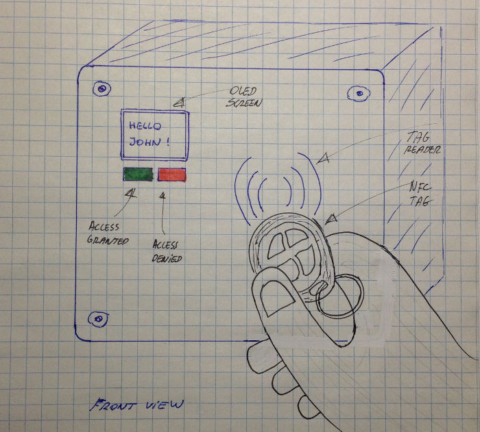
- The front part, the most visible one and the one that could get messy after a while (not all users fingers are clean..). On the front part, there is a place for the OLED and it should be nice to have some symbol engraved to help users to figure out where to swipe their NFC tag.
I envision multiple ways to build those two parts. In a mass production world, I guess it would be plastic injected in a steel mold but it looks a little bit overkill for my project and taking into account the timeframe. Other options should be to print it (I would do someting similar to this) , to mold it, to CNC it. I feel CNC would be a waste of material and 3D printing a waste of time (with not so clean result for the front part). For the moment, I think I will go with laser cutted acrylic for the bottom part and something using a mold for the front part.
Let's build a 2D model using InkScape for the bottom part
Assuming I will laser cut it, my 3D box is a .. 2D drawing (the thickness depends on the material and is fixed).
- Rear: AC/DC supply and SSR has to be attached on it
- Top side: nothing special there
- Left side: nothing special there
- Right side: same part as on the left
- Bottom side: same as top but AC in and AC out have to be inserted there
- Front: I want to fix the cover on it, with screws.
I found out there is an extension for InkScape to design Tabbed Boxes but I struggled to install it and make it work. Here are some hints: first, the folder where extensions are supposed to be is not stable from a version to another. I figured out where to copy the python script by having a look on this

Here is the folder

Here is the security settings for python script

An finaly, here is how a tabbed box looks like

To create a tabbed box, you have to set a few parameters:

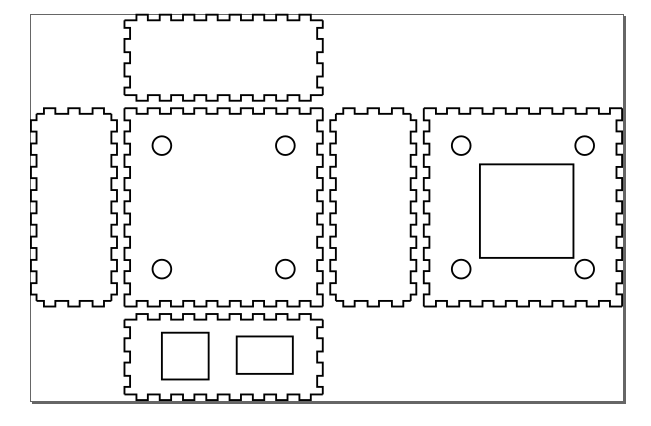
With all parameters set to their default value, here is the output: all parts we need are there but I need to create an opening on the top part and two on the bottom side part

There are two potential strategies from here: the most obvious one should be to update the generated model and to create the openings. Another one should be to modify the python script to customize it to my project needs. I could remove many parameters (like the dividers) and add some parameters to generate the openings. I'm a SW guy.. I will go that way !
An Inkscape extension is a python script (.py) but there is another file (.inx) that describes the GUI
There are too many parameters for this script, some cleanup is required. I will create tabs and I will keep the following parameters in the first tab:
- Units: set to mm by default
- Lenght
- Width
- Height
- Tab width: (to be tested with the real laser cutter)
- Material thikness (to be valided, depends on material availability)
- Kerf (his is the width of the cut, e.g for 3mm acrylic on an epilog cutter this is approximately 0.25mm ): to be valided, depends on laser cutter

I will create a new tab with all the parameters related to openings:
- The distance (x/y) from the origin (assuming origin = top/left for a given part)
- The width and the height (for a rectangle) or the radius (for a circle)

I will move all other parameters to another tab

Here is how the model looks like: there are 4 holes for the copper brass threads in the rear and front parts and there are openings for AC in and out on the bottom side
For more information and to get the source code, click here
Let's build a 3D constrained model using FreeCad. The 3D model will be digged using a CNC and then I will create a mold from there.
More to come in the following weeks, I missed time to work on this one. I will leverage FreeCad for this. My intent is to write some Python code, I found out an intresting tutorial here on how to make it work.
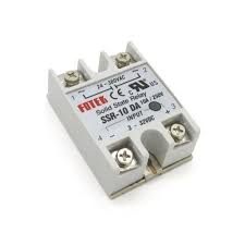
I still managed to build someting in a short timeframe, just to figure out out how to use FreeCad and CSG. This is a picture of a component (Solid State Relay) I plan to use:
And here is the model I created, based on measurements taken on the real object.

The steps to create the model are the followings:

And the source code is here.