Input devices

week 11
March 27, 2019
This week, we need to measure something. To do this, it is necessary to add a sensor to our microcontroller board that we have designed and read it.I decided to read the temperature using a sensor.
Read a temperature sensor
Find a temperature sensor
I went to a store that sells several electronic components and I was looking for a temperature sensor. I have noticed that several types of temperature sensors exist. For starters I saw that there were analog or digital sensors. Analog sensors are those that we need to read an analog value as a voltage. The sensor can affect the voltage by varying the current or resistance of the sensor. Digital sensors are the ones that need to be communicated with them to read the temperature. Several communication protocols exist such as i2C, one wire, serial and many others. Several of these protocols are shown in the networking and communications week.To choose my sensor I put the constraints as if I had to use it in my final project. It must read the temperature between 0 and 40 degrees Celsius. Have an accuracy of 0.5 degrees and above all be waterproof. The only one that met the criteria was this one.
DFR0198 Waterproof DS18B20 Digital temperature sensor
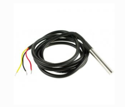
This sensor uses the onewire protocol, which means that it is the communication protocol that needs less connection. It is possible to establish communication with only one wire if VCC and GND are excluded
Designed the board
To make a more integrated board, I decided to put all my inputs/outputs that I wanted to try on the same board so that I could improve it every week. This is the same board for input and output devices.Here's everything I want to put on this board.
- A button if a want to make some debugging
- A LED if a want to make some debugging
- Power LED to indicate if the board is powered
- Reset button if I want to reset the board
- ISP for programming
- FTDI for serial communication
- Themperature sensor (input)
- Light sensor (input)
- Distance sensor (input)
- Water level (input)
- Drive for a stepper motor(output)
I didn't look at how all the sensors work but only the pinout to be able to have the connectors on my board.
Temparature sensor
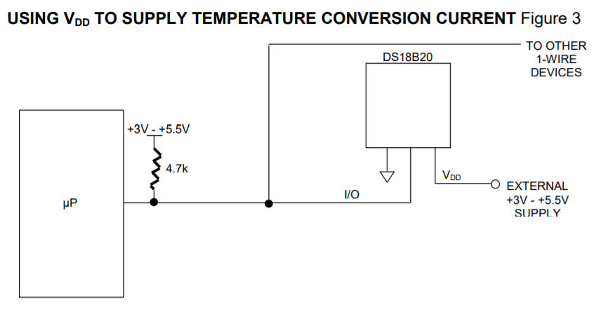
DS18B20 DataSheet

We only need a digital pin, a 5V power supply and a GND. We also need a 4,7k ohm pullup resistor as in the datasheet.
 Light sensor
TEMT6000 DataSheet
We only need one analog pin, one 5V power supply and one GND.
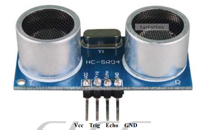
Distance sensor
HCSR04 DataSheet
Water Level sensor
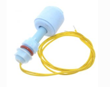
We only need a digital pin because the sensor works like a switch. This means that it sends a digital signal of 0 or 1 if the water drops below a certain threshold. A pin for the 5V power supply. Because the sensor is like a switch, we need a pullup resistor exactly like my switch a resitor of 4,7k ohm is perfect to limit the current.
Stepper motor
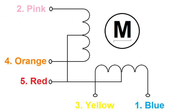
We need 4 connections that can make PWM and one connection to a 12V power supply. The system I have chosen to be able to change my signal from 5V to 12V is by means of transistors. I based myself on the following schematic found online.
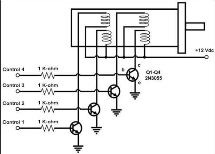
link to image
It is never good to leave a circuit open so I decided to put a pullup resistor on each transistor. I just need to put a small resistance to create this pullup because the current comes directly from the source so I don't limit the current with this resistor.
To calculate the resistor of the base transistor, I relied on this calculation. link
Here the datasheet of the transistor I chose.link
Here are the important data found in the datasheet.
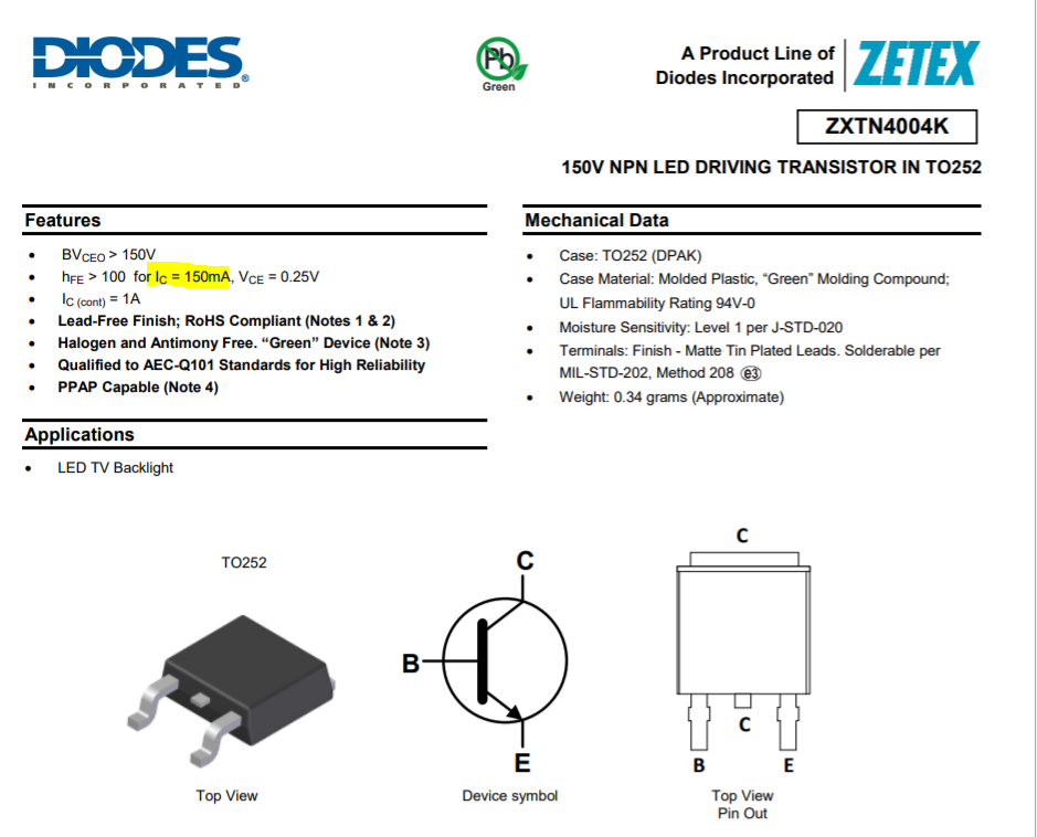
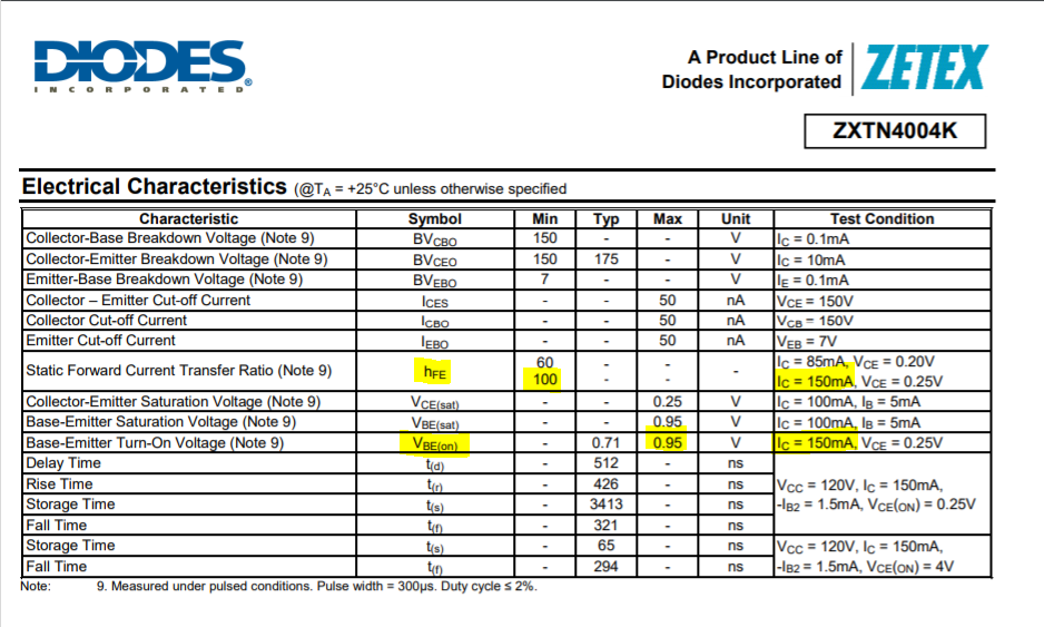
Here the calculation for transistor.
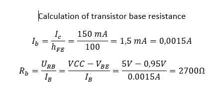
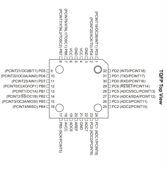
Now that I have the list of sensors to put on my board, I have to choose on which pin of the microcontroller to connect them.Because I have a lot of sensors, I decided to use the atmega328p microcontrollers because it has more connection and internal memory.
Here is the pinout of the microcontrollers
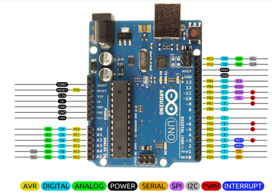
Another image that has helped me a lot with design and programming is this one. You can see all the different types of pin and also the corresponding number for programming in light blue.
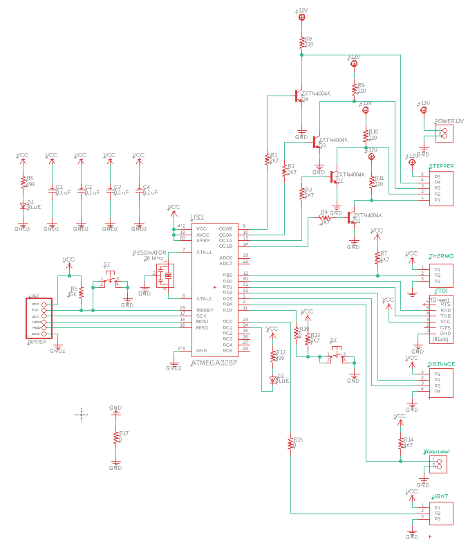
Here is the schematic, it should be noted that there are 4 decoupling capacitors on this board.
For the board, I placed the decoupling capacitors and the resonator closest to the microcontrollers to avoid loss problems. I then decided to put my traces at 15 mil because we could see the milling difficulties below that. The tracks for the 12V power supply are larger because a larger current will flow. It is always better to have bigger trace as possible to avoid problems.
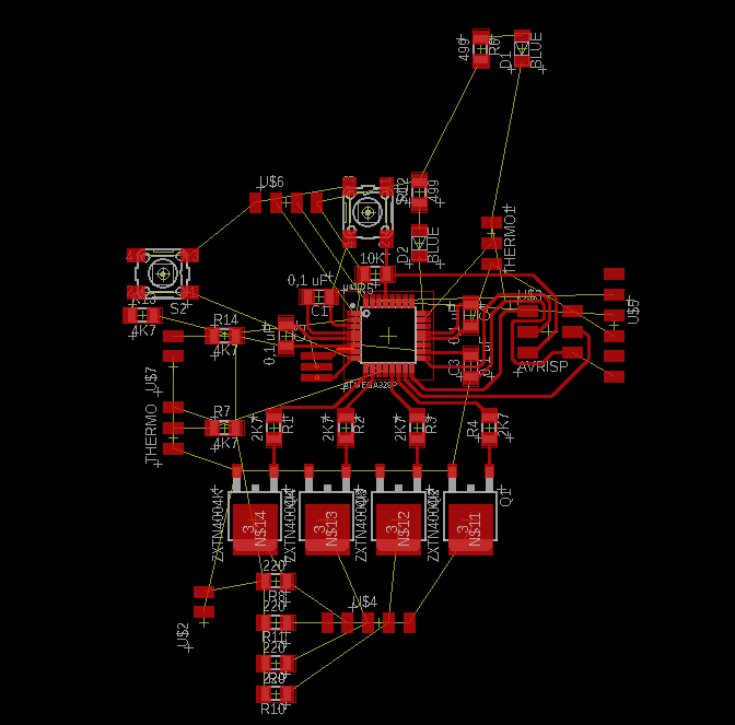
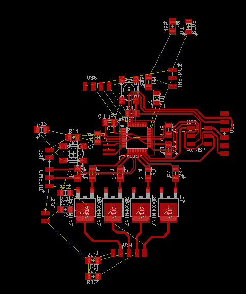
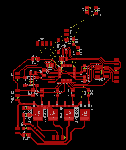
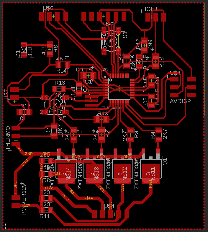
Here is the final result with the ratsnest.
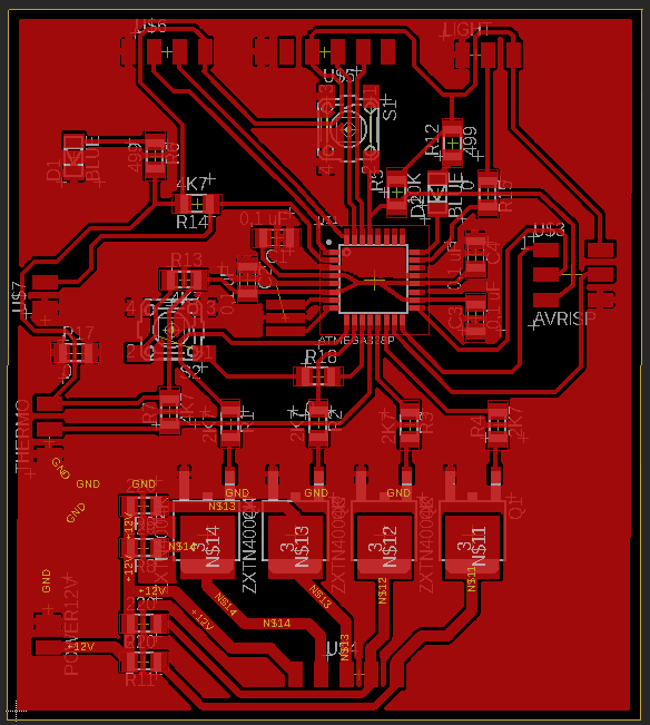
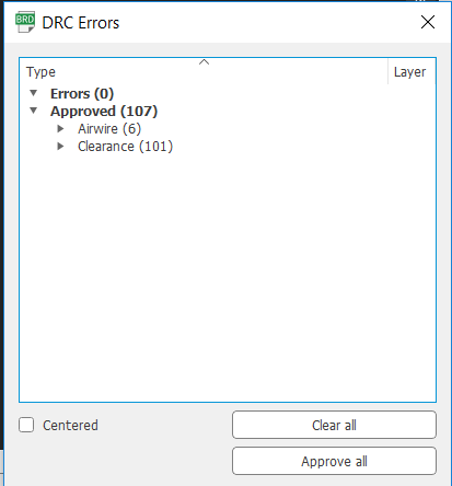
In the DRC, I put a minimum space of 15 mils between all. No error in the board except the airwires that are caused by jumpers and the 101 clearence which is the distance between the pins of the atmega328p that I can't change.
Milling the board
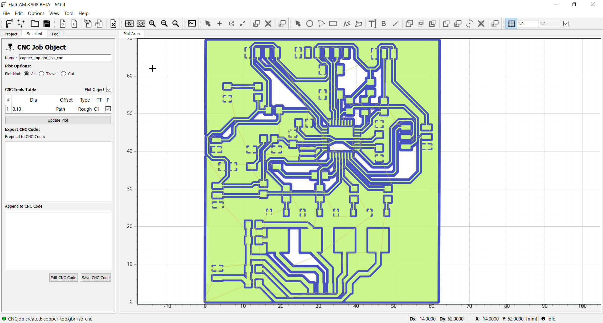
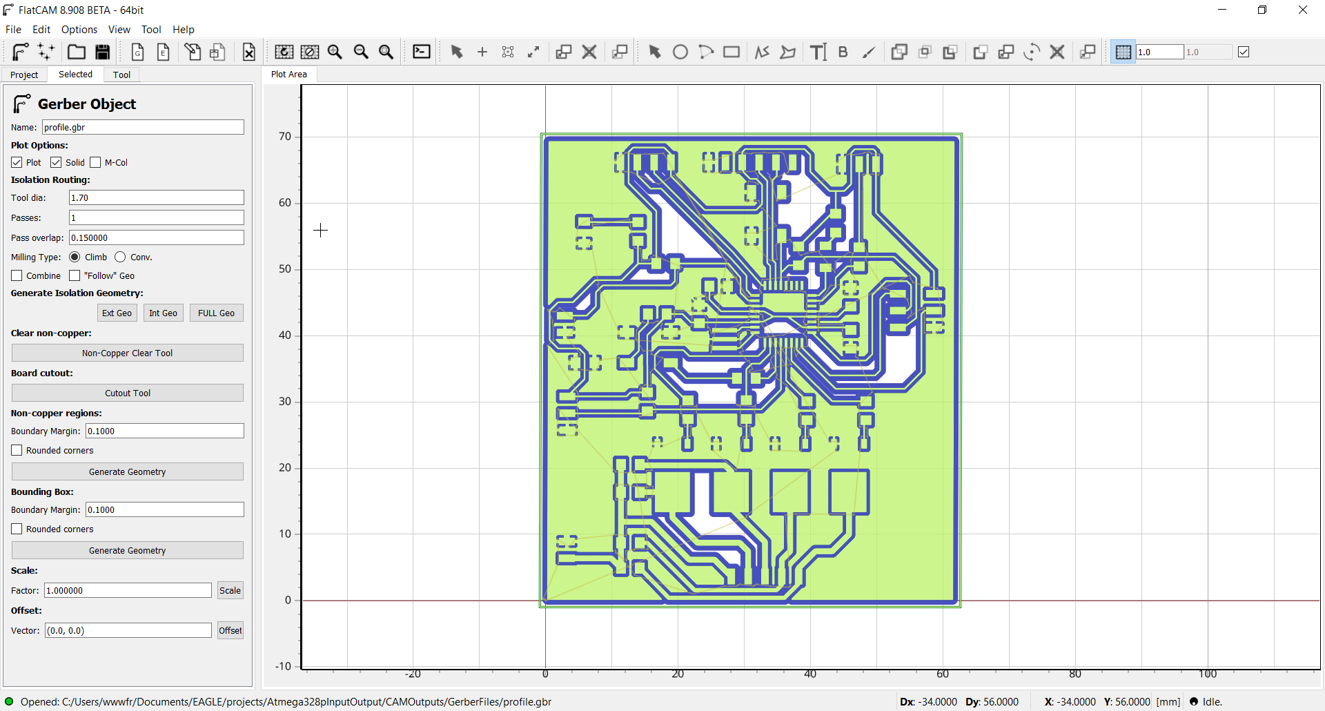
To start, I imported my board file into flatcam to be able to generate Gcode files for the CNC. The first job is the top of our board. It is necessary to make a full geometry and enter the following parameters.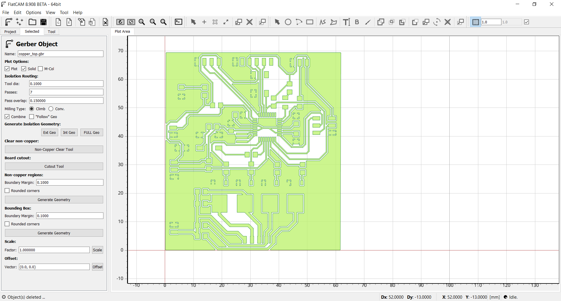
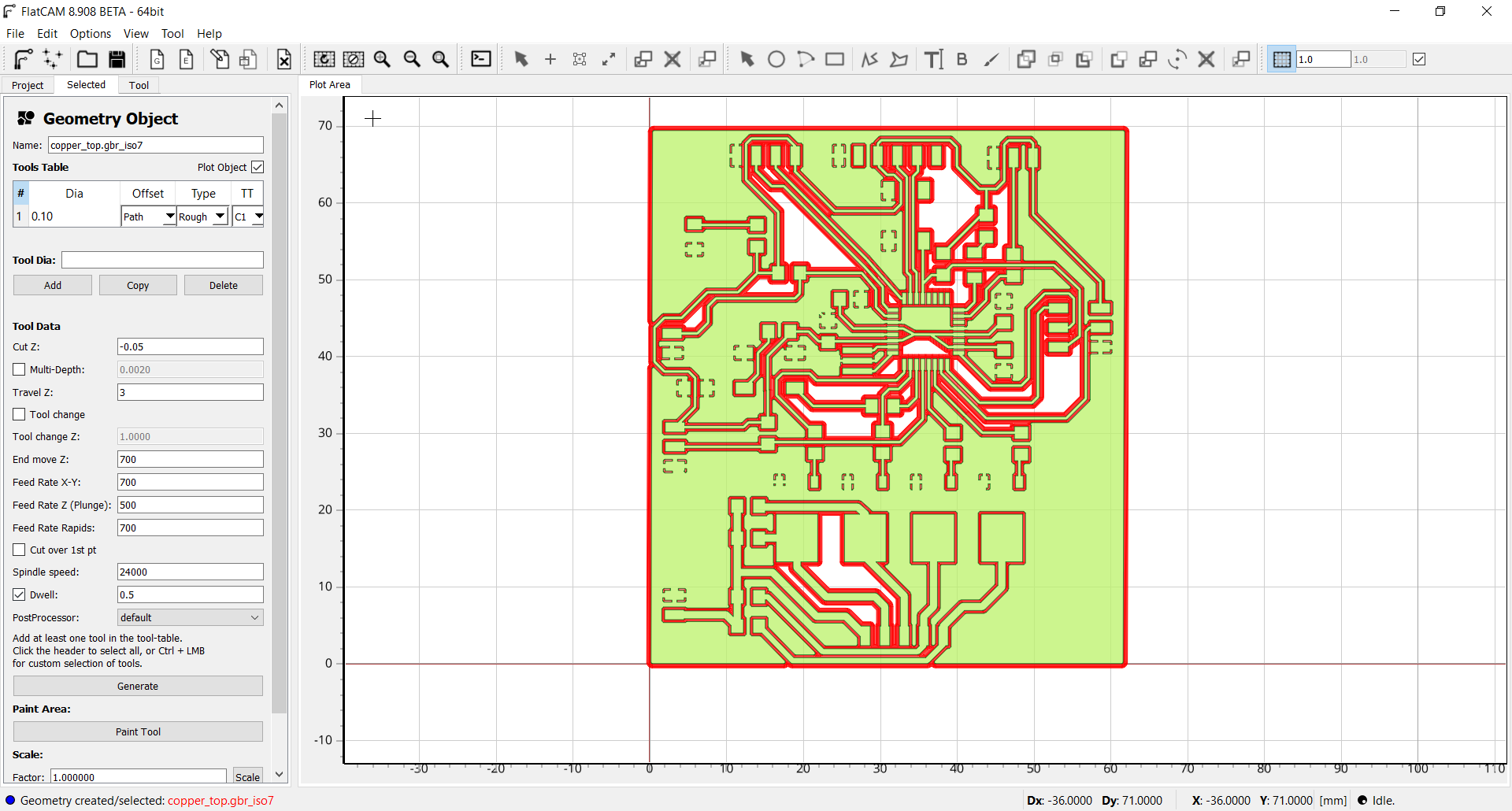
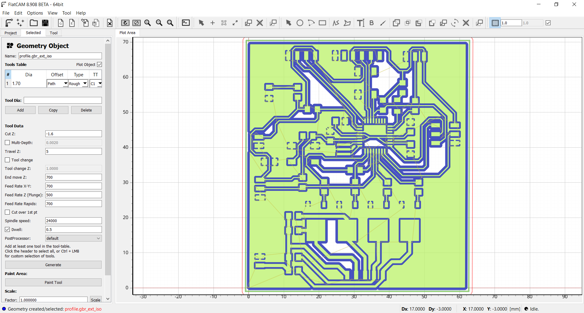
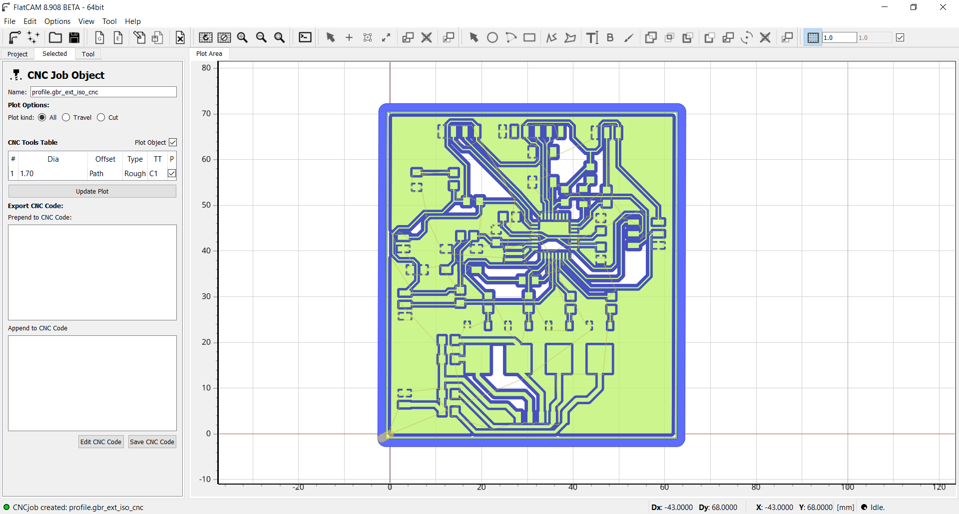
Now to make the board profile, it is important to choose extern geometry.
 The best way to make an origin is to do a conductivity test with a multimeter. Simply place a probe on the board and a probe on the tool. Go down from 0.01mm in Z steps to conductivity.

When the tool is positioned, it is necessary to indicate the 0 to the CNC by pressing the two buttons at the top left of the remote control.

Here the board during the milling.


Soldering the board
A good advice when soldering is to always start with the most difficult component. In this case it is the Atmega328p microcontroller. If we ever miss and damage the PCB, we will not have wasted a lot of time soldering the other components. It is important to align all the pins of the microcontroller before doing the first soldering. The liquid flux can help to keep it in place because it is a little sticky.

For the rest of the components it was easier because they were the larger components. The only one that is a little difficult is the resonator because the traces are not much larger than the component and it must be soldered on each side.


Here is the final result.

Program the board
To make my program, I used the Arduino IDE. To be able to program the Atmega328p I have downloaded the corresponding board manager. To see more details on the installation you can refer to my week 9:Here is the link for the board file: atmegaga328p.

I also installed the following two libraries (The librairies are include in week files):
OneWire Library
DalllasTemperature Library
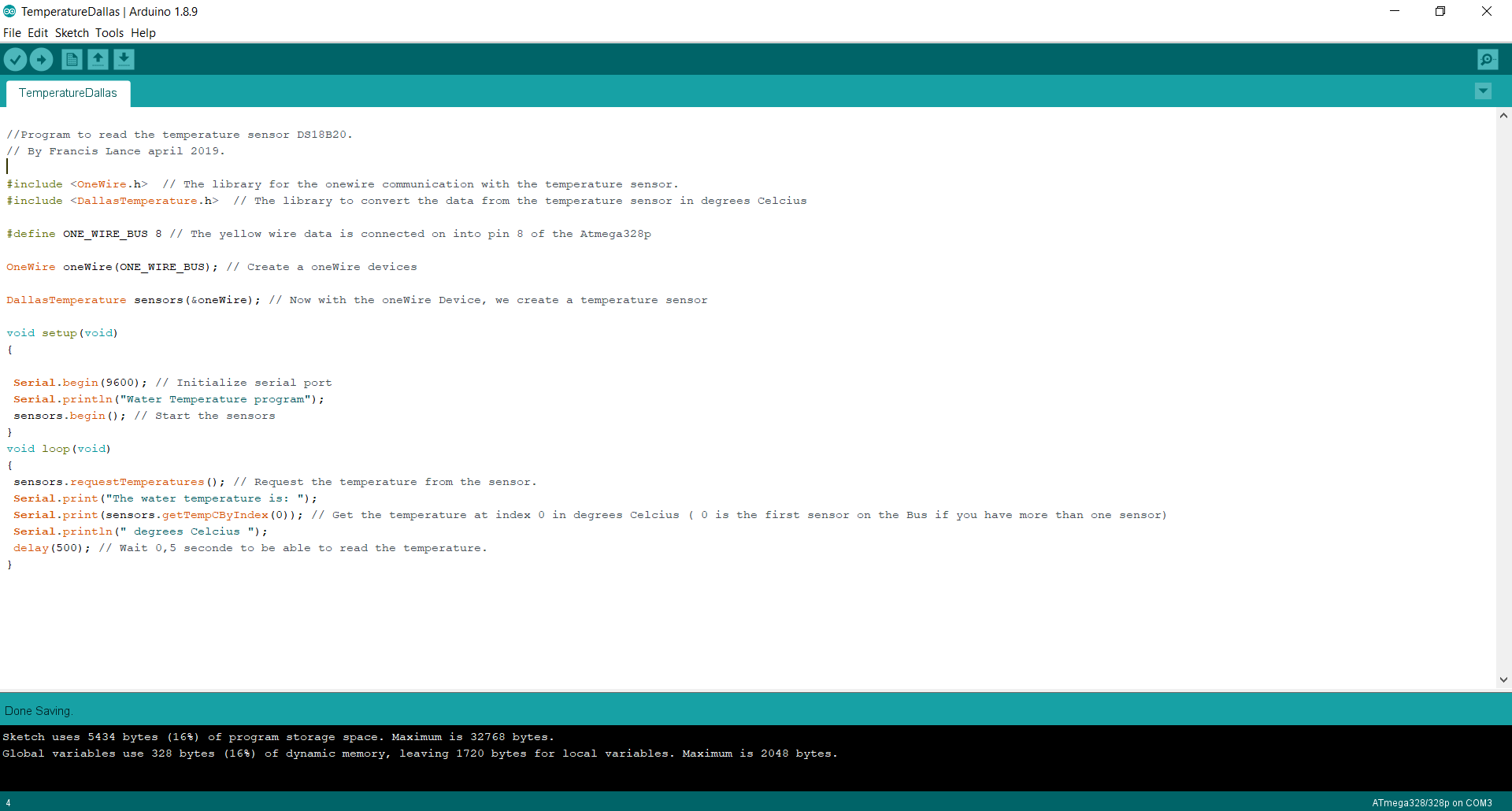
Here the program to read the temperature with the DS18B20. All the comments are in the program.
Result
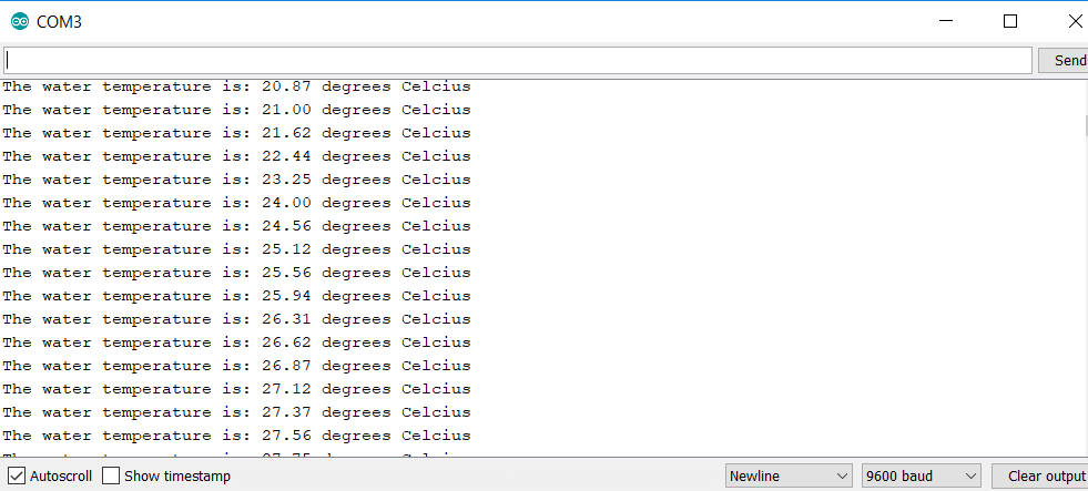
To be able to test my temperature sensor. I put my hand on the sensor to raise the temperature. Seeing the temperature rise or fall does not mean that we have the right temperature. To validate the temperature I obtained a temperature of 0 degrees Celsius by putting ice in the water.Here you can see the temperature rise because I put my hand on it.
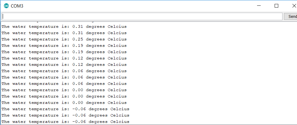
Here the temperature sensor is in the water with ice. We can see that we are very close to 0, we can see that the sensor is well calibrated and that we read the right temperature.
Here the video of the result
Group assignment
This week, the group assignment was to read a digital and analog input. For that, I used the arduino IDE to write the program using the libraries already integrated. I used the board I designed this week to be able to do the project. I used the connector for the light sensor (pin PC0 - #23 on the chip and #14 in the program) to be able to do in the program.Digital read
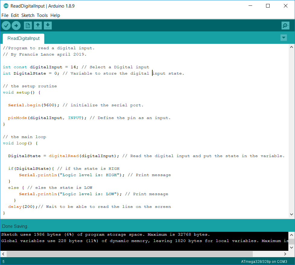
The easy part is to read a digital input because there are only two possible values. The first is 0 (LOW) and the second is 1 (HIGH). I used the digitalRead() function to read the state of the pin. It is important to choose a pin that is digital otherwise the function will not work. In my case, pin 14 is digital and analog so no problem.

Here is the program. All the comments are in the program.
Here is the result.
As you can see in the video, when I turn on the power source you see the HIGH state appear very quickly but when I turn it off you see a delay before seeing the LOW appear. This is caused by the power source because it contains capacitors and when I turn off the source, it takes a few seconds for the capacitors to empty and the output to reach 0V.
Analog read
For the analog reading part, the reference pin (AREF) of the microcontroller must be at the maximum value that we can read on the pin. In my case, it's 5V. Also, the ADC must be powered with the AVCC pin which is also at 5V. So here is the first reading I got with my program.
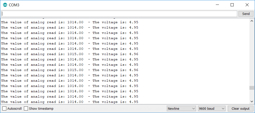
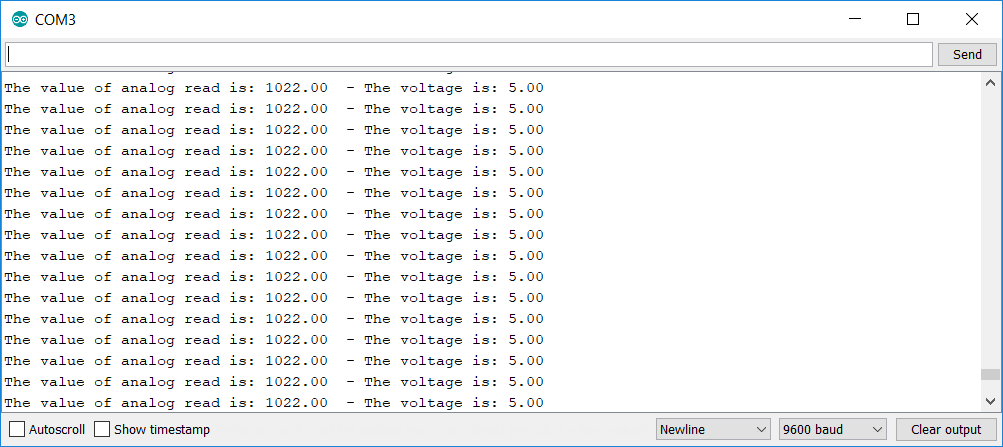
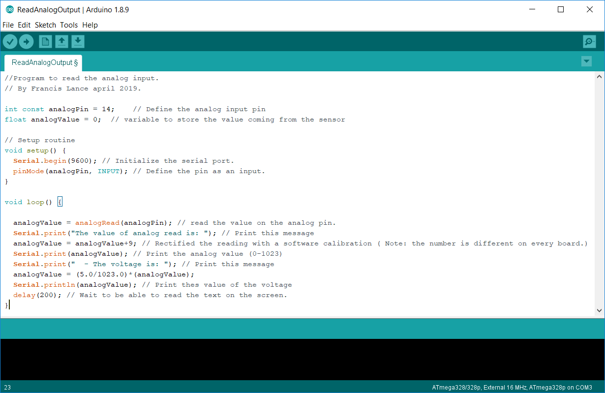
Knowing that the output is connected to a 5V source, we can see that there is a small difference. We will therefore make a software csalibration of our input to have a more accurate reading. The analog reading gives a value between 0 and 1023 ( 0V and the reference which is in our case 5V. For that, I set the input to 5V and I get the reading 1014 and which should be 1023. So we have a difference of 9 that I add to my reading. We can now see that when I put the sourve at 5V I now read 5V.
Here is the program. All the comments are in the program.
You can download all the files of the group assignment this week right here.
You can download all the files of this week right here.