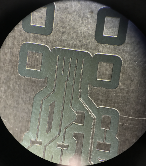
This week, we must design our first electornic circuit. The circuit is actually the programmer for the micro-controller that we will use to program all the next circuit in the course as well as our final project.
Prepare the file for the CNC
The first thing to do to make our pcb is to prepare the file for the CNC. For this we use FlatCam software. It is important to enter the parameters correctly. It should be noted that the parameters are sound in the metric system.
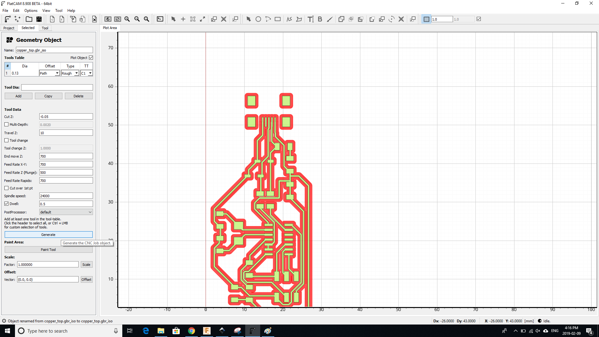
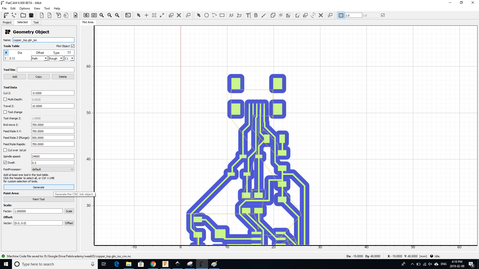
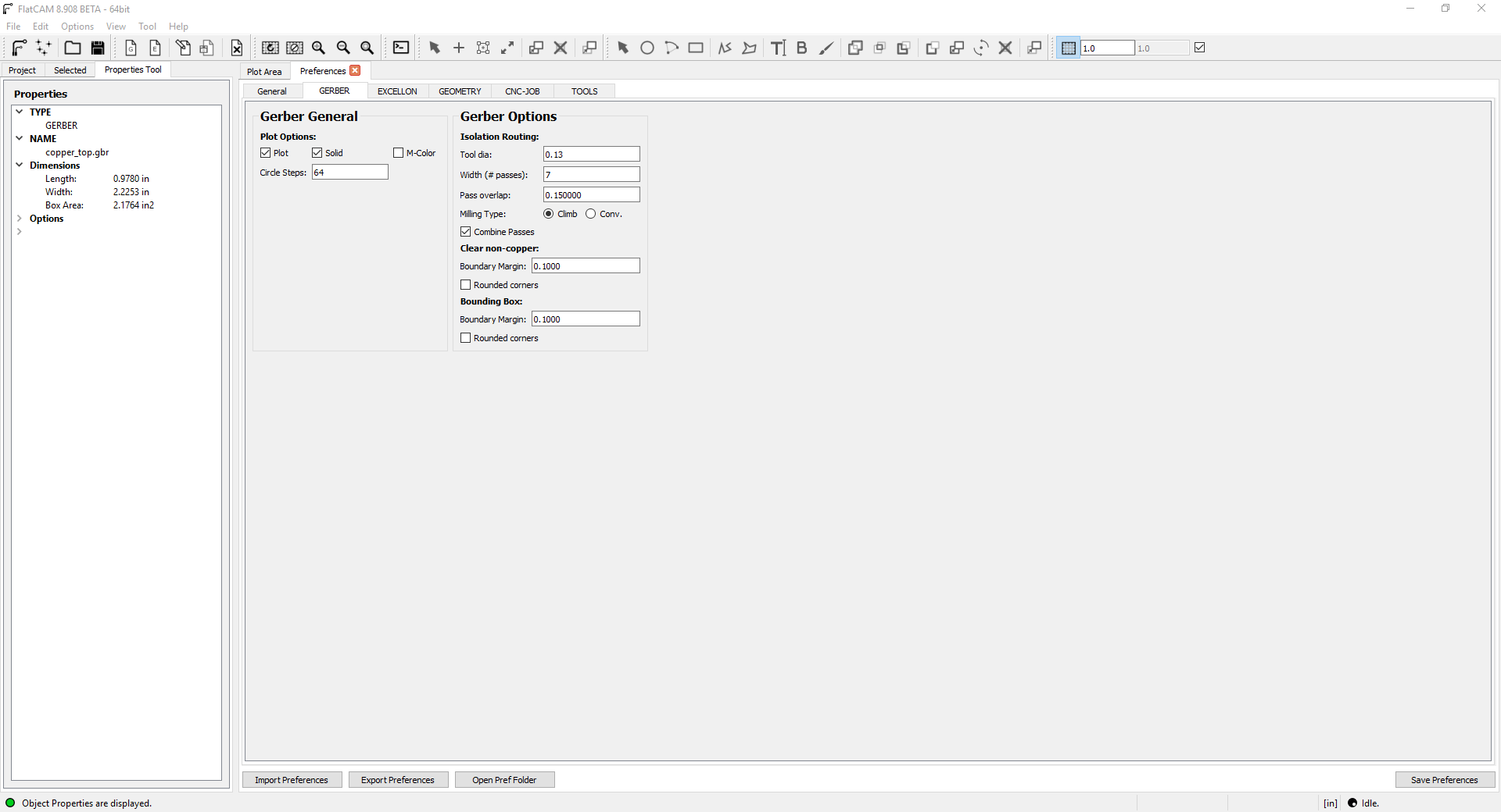
The last step before sending the file to the CNC is to put the parameters in the gerber file.
Group assignment
The person who documents the group assignment this week is
Bomi Doh.
Manufacture our circuit with the CNC
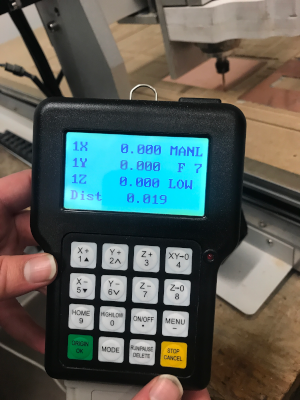
To start with the CNC it is necessary to position the origin with the remote control. With the arrows, we move the head of the tool and when it is well positioned we press the two buttons on the right to set the origin.
The tip of the tool should only touch without putting any pressure on the plate can be seen in the following image.
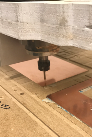
The first attempt did not work because the tip of the tools was a bit too low so the tool has dug too much into the pcb.
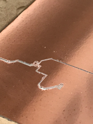
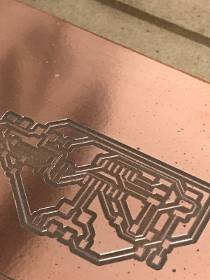
It can be seen in this picture that the tool removes perfectly the copper layer.
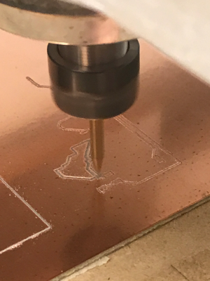
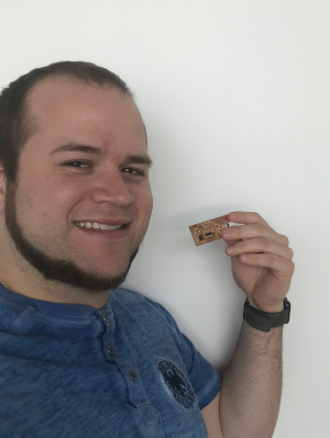
Here is the final result of the pcb.
Solder our circuit
It is now time to weld the components on our PCB. Here is an example of a surface welding station.
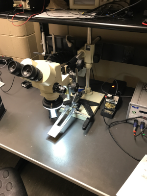
When you do soldering, it is important not to breathe the smoke. That's why you have to have a smoke extractor as in the picture
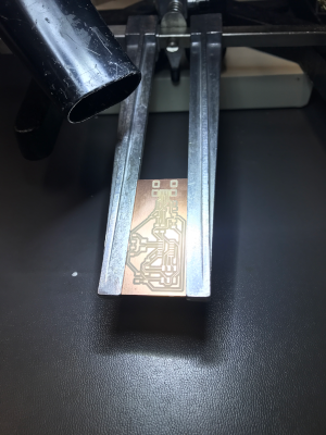
This is the USB connector of the PCB seen in the microscope. We now see why the microscope facilitates surface-mount soldering. The components can be very small and you have to be careful not to short-circuit the connections.
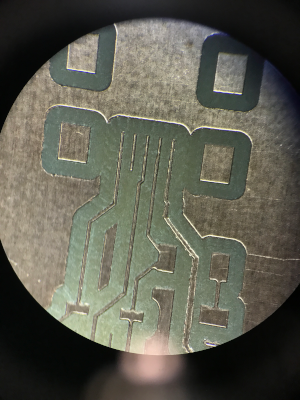
To solder, you have to use a product called flux. Flux helps heat transfer and adhesion of tin to PCB copper. You have to put some just before the solder and it avoids having a cold junction. It also helps hold the components in place because the liquid is a bit sticky.
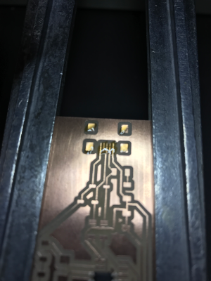
To solder the micro-controller, it is very important that all the connector of the chip are directly on the copper before soldering it.
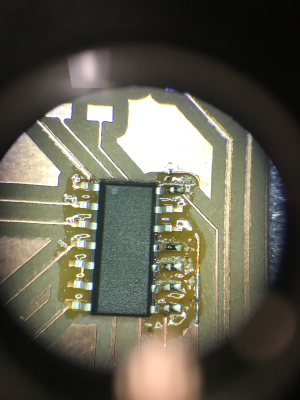
Soldering in progress. I finished the usb connector and the micro-controller.
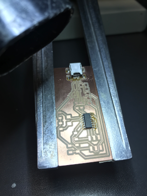
Soldering in progress. I finished the SPI connector, the crystal and the zener-diodes.
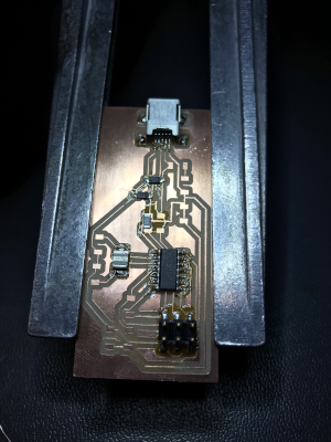
Almost finished, we must now weld the last components. Subsequently, clean the PCB with remover flux to remove excess flux.
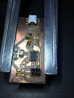
All components are soldered and the PCB is well cleaned. Here is the final result.
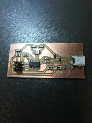
Trouble shooting
We are able to program the programmer but when connected to the computer, it detects an unknown device.
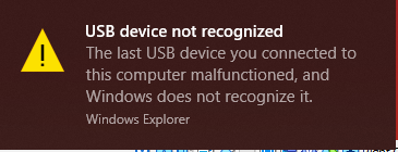
we check
- All components are well soldered
- No short circuit
- All components have good values
- Zener diodes are in the right direction
- We compared with a circuit of last year
- We redid the PCB several times
- We tried three different versions of the design
- We checked all the drivers
- We tried three different OS (Ubuntu, Windows 10, Mac OS)
- We tried three different programmer
- We tried different kind of crystal
- We installed a lot of different drivers
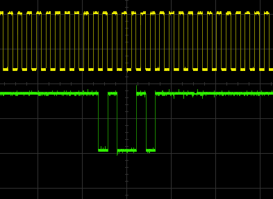
- We check the reset line with an oscilloscope (see the image bellow)
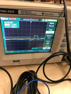
The rest line is not perfect but should work. The reset line should be square like the green line.
Finally find the problem
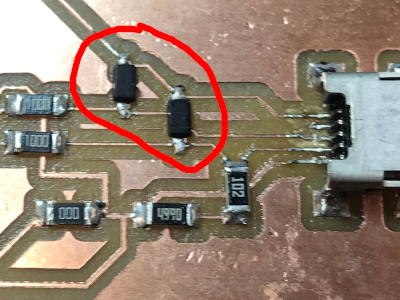
The problem we have been searching for so many hours was a problem with zener diodes.
 Philippe Libioulle
found the problem on a
forum and the problem was the value of the power of the zener diode. We used a 1W and for this to work we must use 1 / 2W. We had to check the value of the diode when we checked all the components but only the threshold value of 3.3V but not the power. We thought that if the value was higher than it would not change anything like a resistance. For resistance, if the power is higher it does not change its operation but only at its level of heat dissipation. For a zener diode, the power corresponds to the power consumed by the diode and therefore it could not have enough power to communicate with the chip via the USB port. On the other hand, for the programming all worked well because we communicate with the chip by the port ISP and that is why we had no problem.

I re-solder the two new 3.3V 1 / 2W zener diodes and all started working.
Programming the board
After solving the problem, it was easy to program the board. Just make sure the makefile is well set. A small thing to check is to choose the right programmer. Since we use a usbtiny programmer to program our board, we choose the first options.
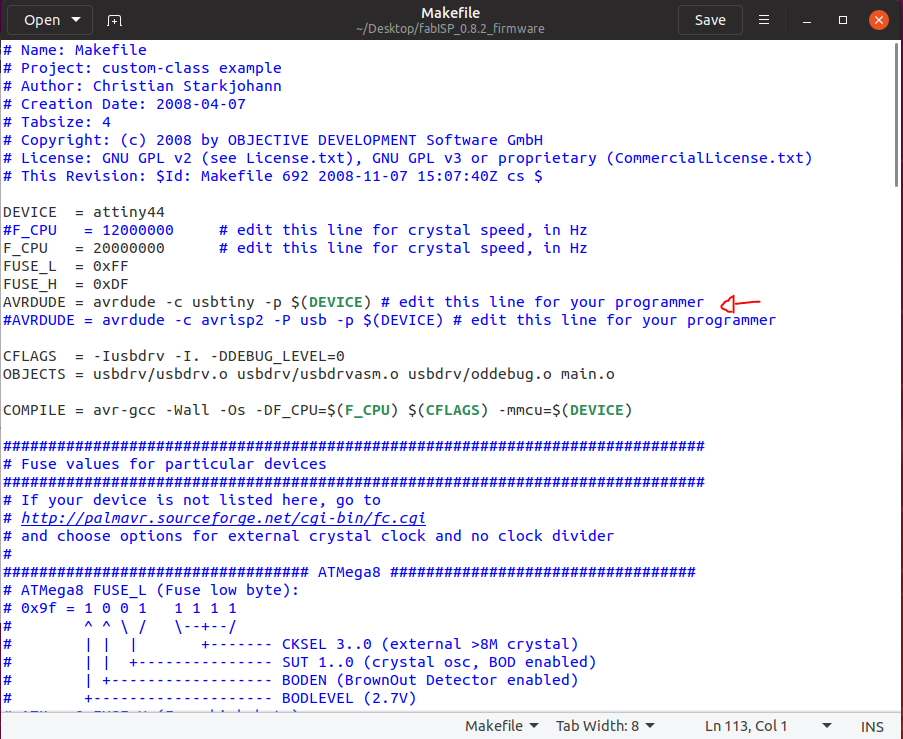
Thereafter, you must use the command make clean to remove all files outdated.

After that, you have to use the make hex command to get the files necessarily to the programming of our board.
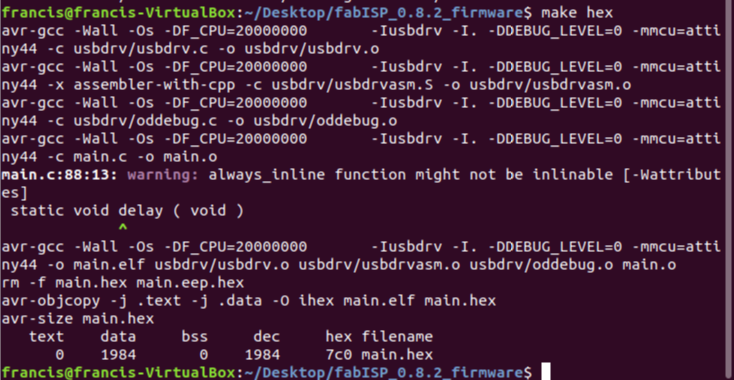
After that, you have to use the make fuse command to be able to adjust the parameters of the chip
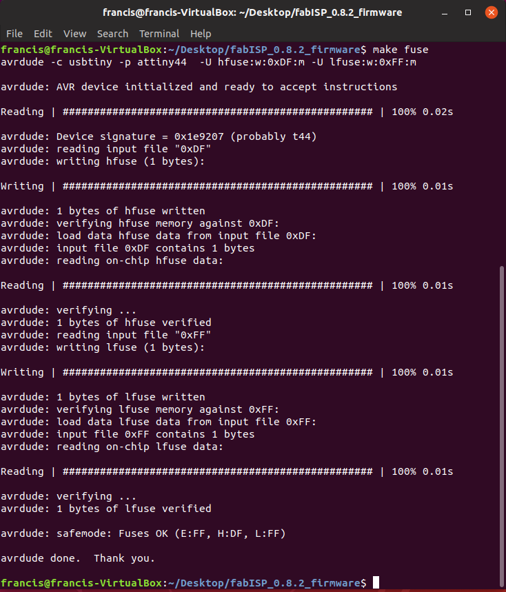
The last step is to program the board with the command make program to upload the code into the chip.
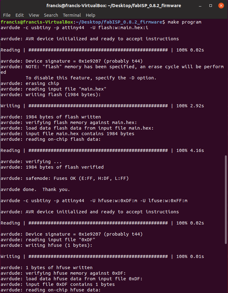
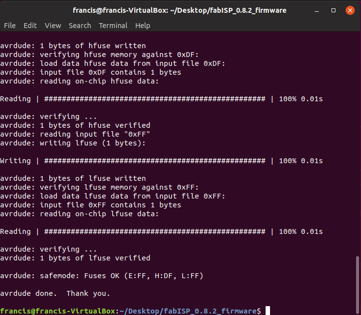
Now we have to check that everything is working properly. I unplug the programmer and usb wires to connect only the new programmer to check if it is detected. For that, in the same terminal it is necessary to use the command lsusb to see all the device USB detected by the computer.

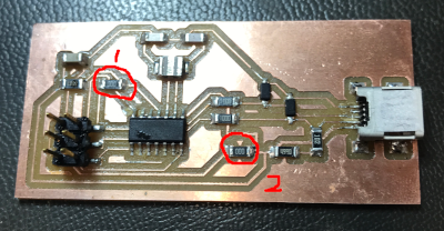
The last step is to prevent our board from being programmable. For this, remove the resistor 1 indicate in the picture that is used to reset the chip during programming. Remove the resistor 2 indicate in the picture that is used to feed the power to the chip through the SPI connector. Now, the only way to power the chip is through the USB port. There is also a way to make it more permanent by destroying the fuse inside the chip with command line but I find it too permanent for me. Because if we want to make updates on the board we simply solder the two resistance 0 ohm and
it is now programmable again.
Hero shot
You can download all the files of this week right
here.
