Computer-aided design
week 3
January 30, 2019
This week we need to explore different kind of software in computer computer-aided design.
Explore 2D CAD raster
Gimp
The first software that I will try is gimp. Gimp is a very powerful free and open source photo editor. It looks a lot like a Photoshop who is another photo editor most popular in photography industry. I will use gimp to edit pictures that I take during all the Fab Academy journey. For the next example, I want to desaturate the background of an image to reduce the attention because I want to put the title of the week over the background.You can download the software here.
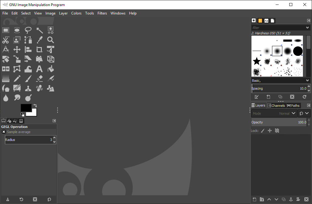
The interface of Gimp it looks like that when you open it.
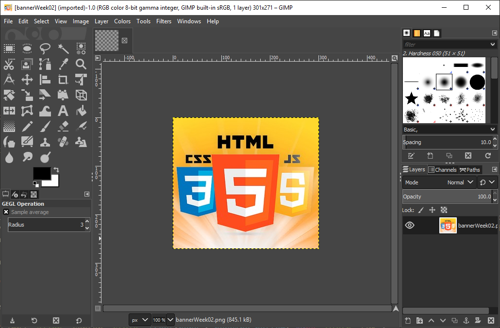
The first step is to open an image to edit. What I like of gimp is the drag and drop to open a file are supported.
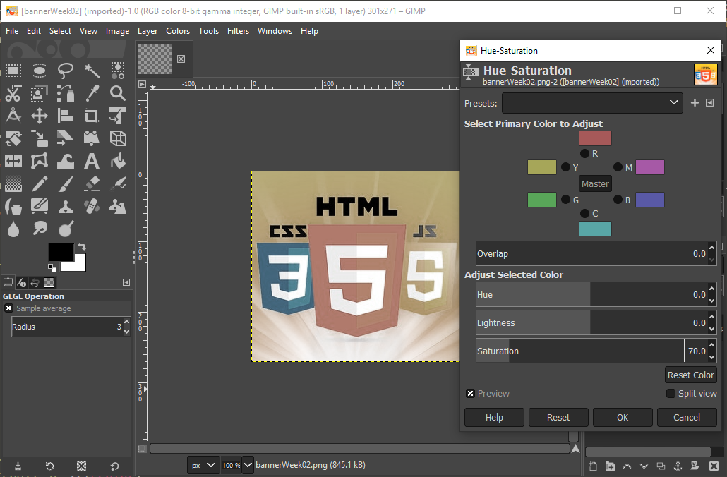
The next step is to find a way to desaturate the image. I found a lot of ways to do it during my exploration and my favourite one is to go directly to the menu Hue-Saturation.
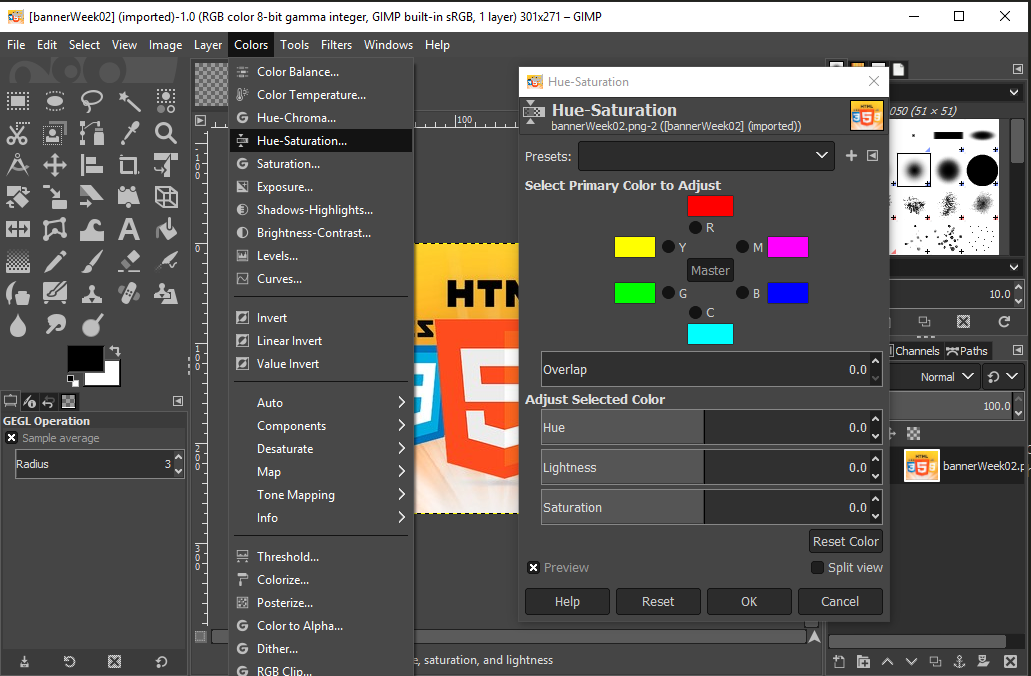
To desaturate an image is a way to transform your photo in a black and white picture but not completely. The more you go in the negative value less the picture will have some colour. Like here I enter the value -70 in the saturation section.
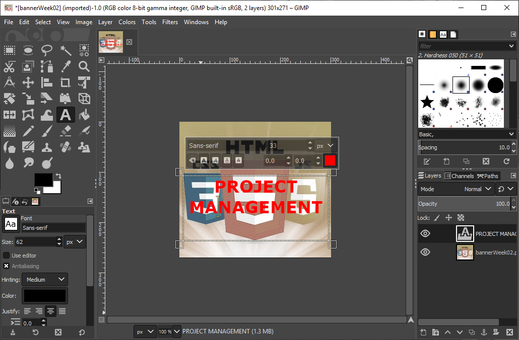
For insert text over an image, you need to use the tool text and to draw the delimitation of the text. After you can change the colours, the font, the size of your text with the little menu just over your text.
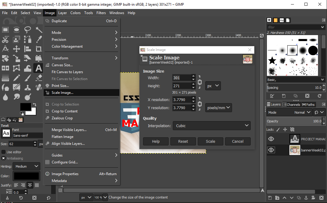
Another tool that is really important in our context is to reduce the size of the image. The size of the website can't exceed 300 MB so is not a good idea to have pictures of 3 MB. You can go to the menu image and choose scale. After that you can reduce as you want. A good size for a website is around 300 pixels on one side and the size is around 100 KB.
Photoshop
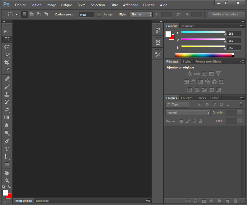
Photoshop is another photo editor but this one is not free. I install a trial version to compare with Gimp and I do the exactly same example. I prefer the interface of Photoshop because I found easier to recognize tool logos. I will not use Photoshop during the Fab Academy class because the trial is very short so I prefer to use a freeware without limitations.
Explore 2D CAD vector
Inkscape
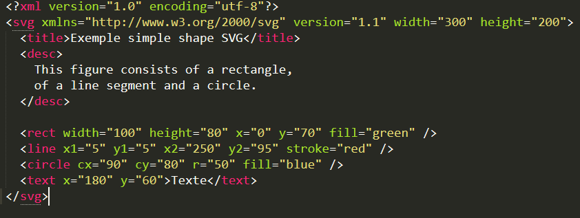
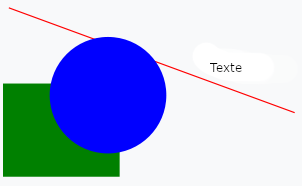
The first software that I will try is Inkscape who is a vector editor. A vector editor is another way of creating drawings that is shaped with fillers. Shapes are a list of coordinates with dimensions and properties. Here is an example of a .svg file that is the format used by the vector editor.Here is an example of an image in svg. You can see the code behind the image on the left and the result on the right.
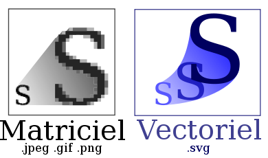
One of the big advantage when working with vectors is that there was no pixel. That is to say, if we resize the photo, we can never see the pixels because there is none. The quality of the image remains the same regardless of size.
I want to create a logo for my final project. The laser cutter needs a vector design to be able to cut and engrave the logo.
you can download the software Inkscape here.
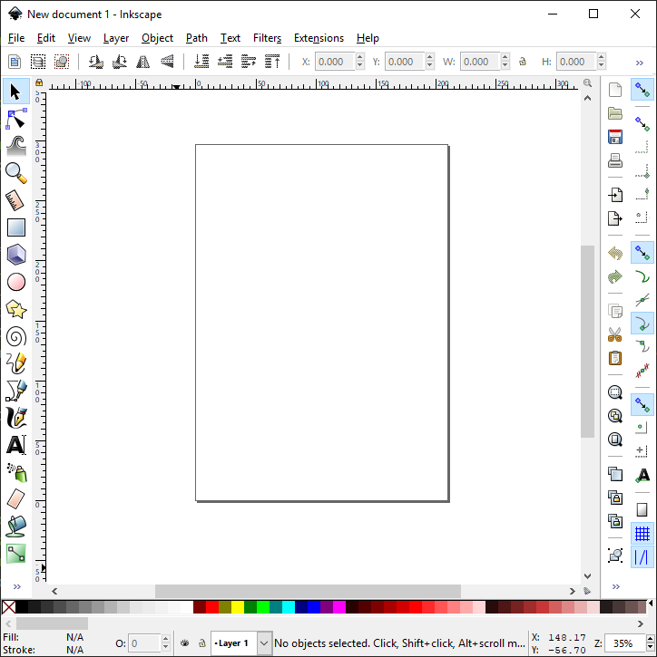
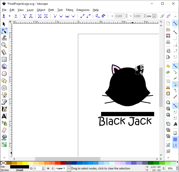
The interface of Inkscape it looks like that when you open it.
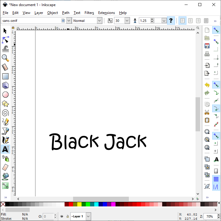
The first thing I want to put in my logo is the name of my fiance's cat. I will use the text tool to write its name.
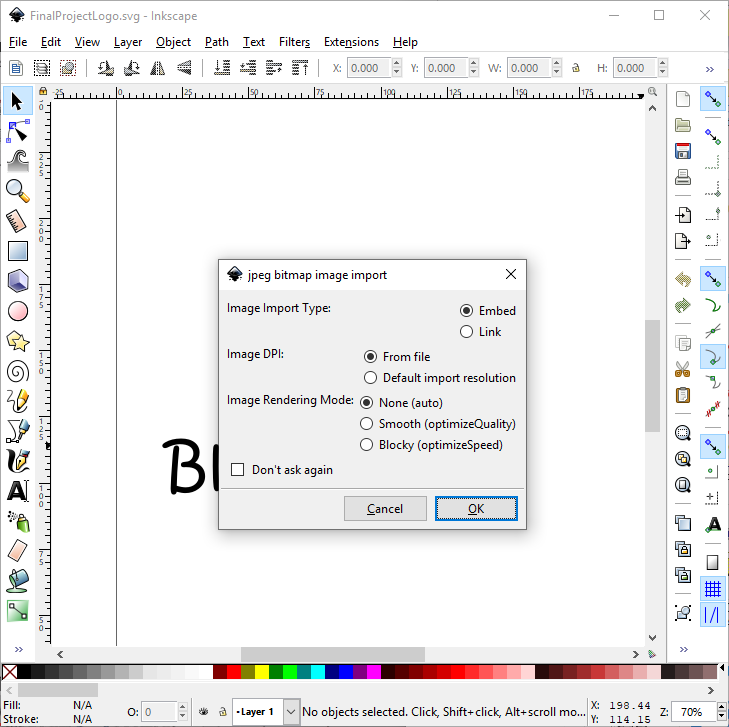
Subsequently, I decided to look for a cat image because I am really bad in drawings to be able to trace it in Inkscape. I drag and drop the image directly in Inkscape to import it.
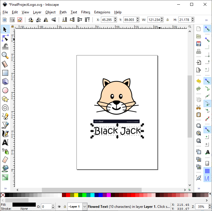
I resized the image to make it the right size. To keep the same size ratio I kept pressing control and pulled the corner of the image.
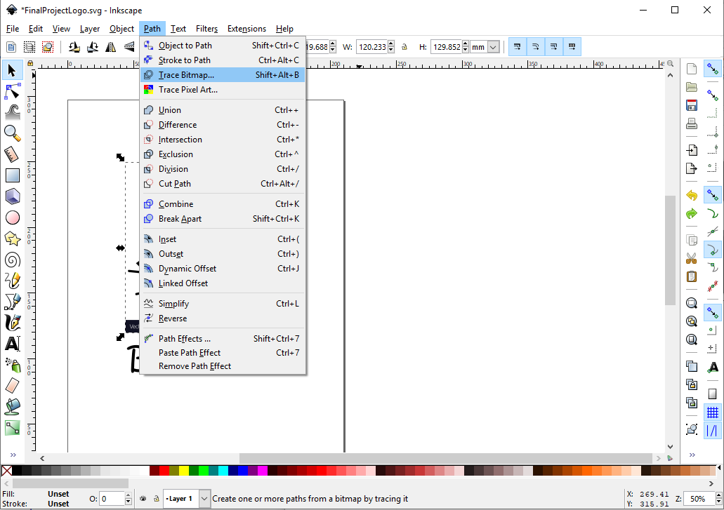
For the next step, I was in the path menu and I chose the trace bitmap option.
I adjusted the options until I got a good result. Do not forget to check the preview box to see the future result.
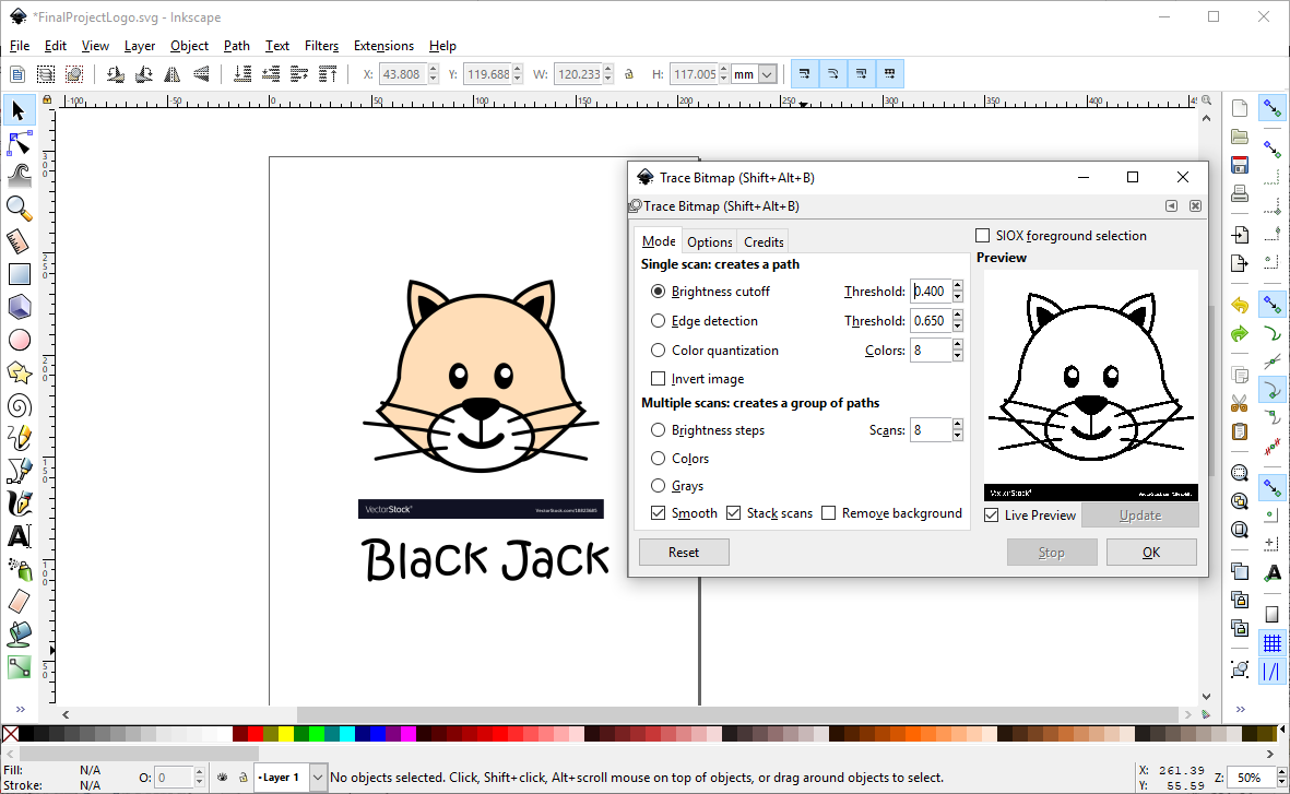
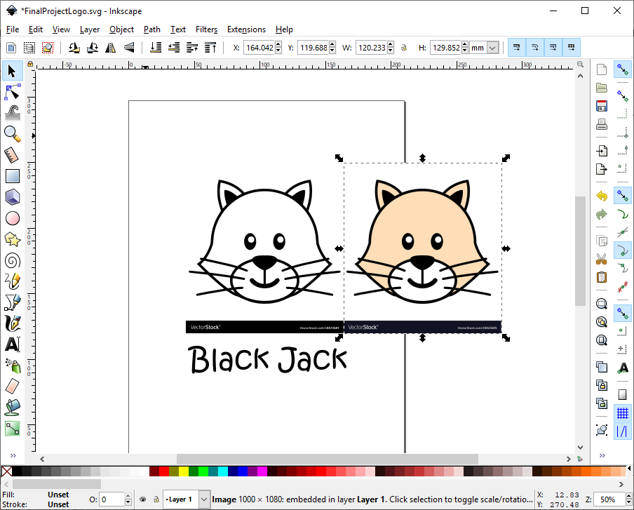
We get a copy of the image in black and I moved the original image to see the two separate images.
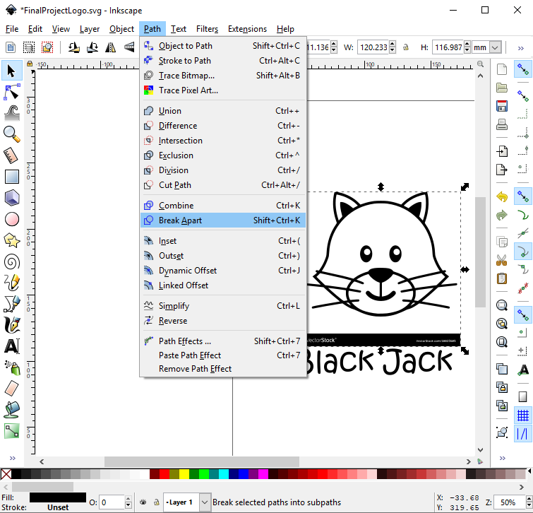
For the next step, I was in the path menu and I chose the break apart option.
Now it's time to color our drawings. You must select the edit path by nodes tools in the left menu.
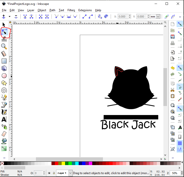
When you go over the image, the outline of the sections will turn red. You have to select them and choose the color at the bottom of the window.
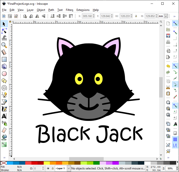
After having colored everything here is the final result.
Illustrator
Like Inkscape, Illustrator is a vector editor. I made the same example as with illustrator. By cons I chose not to use Illustrator for the same reason as Photoshop. The reason is that Illustrator only offers a trial period that does not cover the duration of the course. I prefer to use freeware.
Explore 3D CAD
Fusion 360
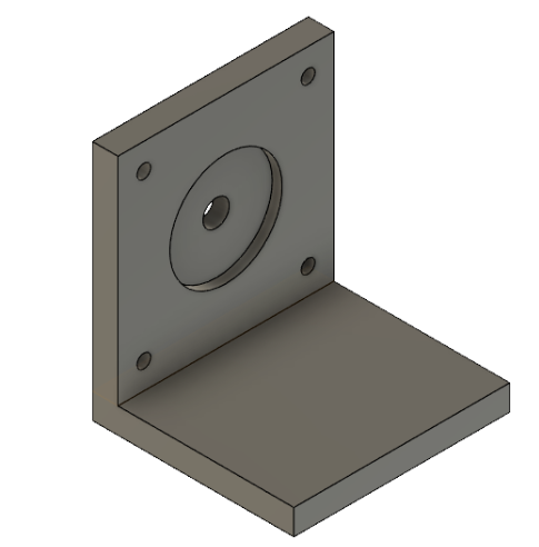
The first software that I will try is Fusion 360. It's a CAD software who is free for hobbyists and paid software for commercial use. We can use the free license during the Fab Academy.I will use the CAD software to draw the stepper motor support that will be in the peristaltic pump.you can download the software here.
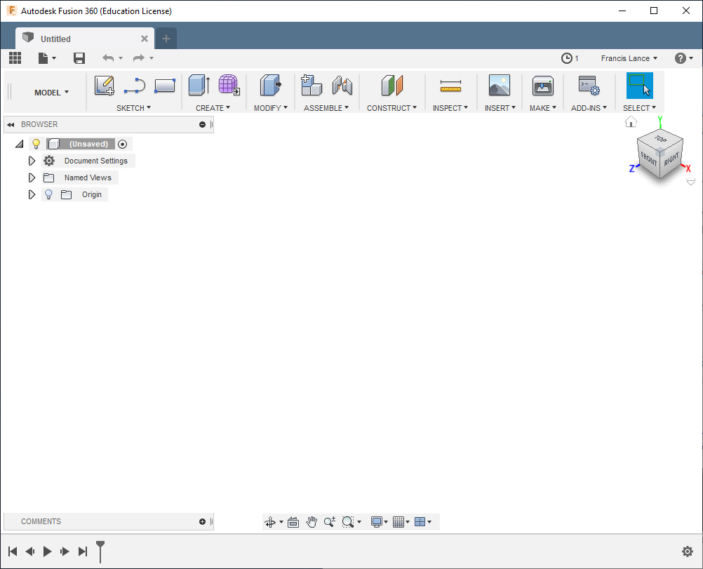
The interface of Fusion 360 it looks like that when you open it.
This is the stepper motor that we have to draw a support.
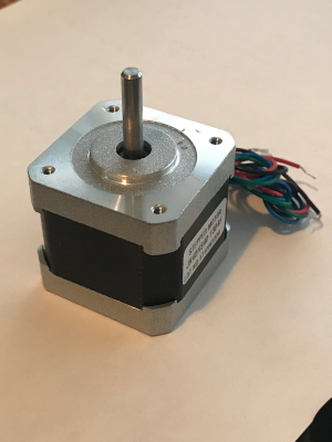
We need to take some action before we can start drawing our part.
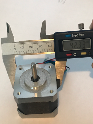 |
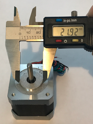 |
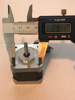 |
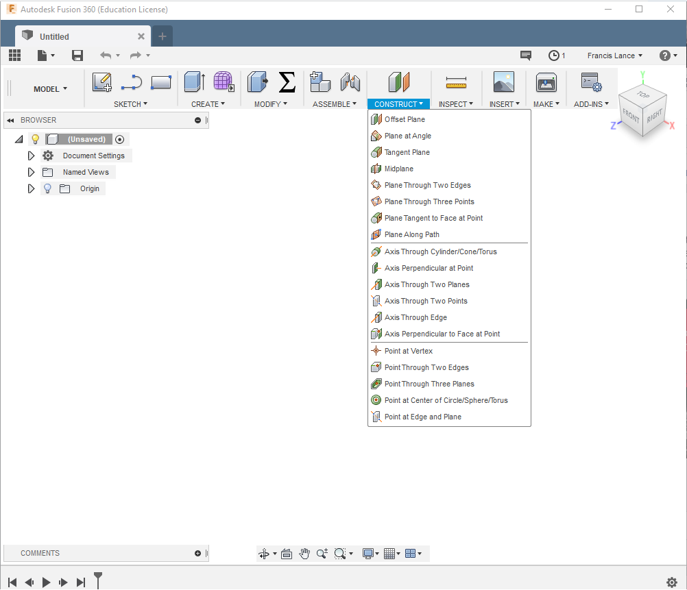
The first step is to create a plane in 3d space. I chose to create a plane on Z and X to start. It is on this plane that we will be able to draw a 2D shape.
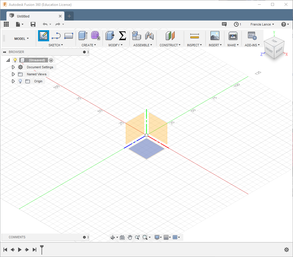
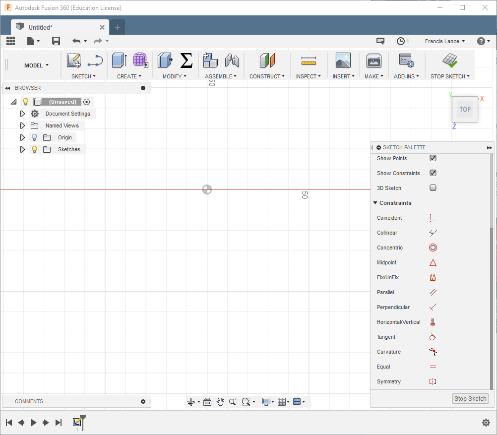
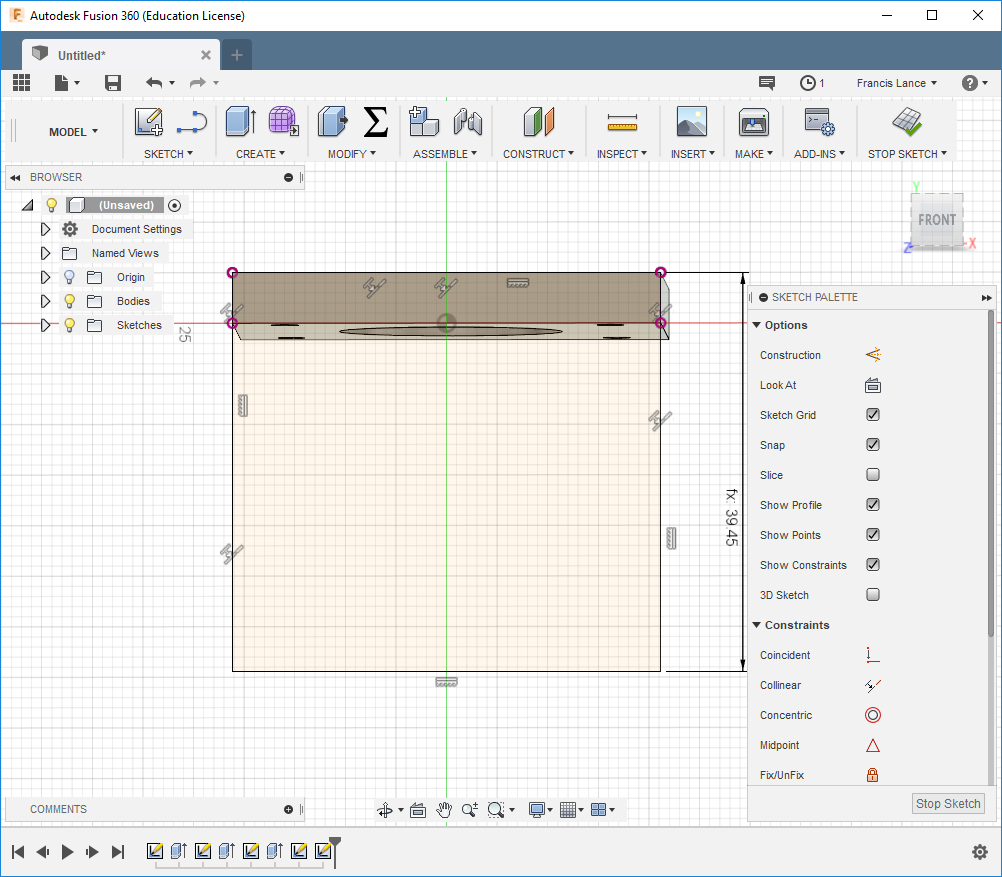
Now we are in the Z and X plane. There is the constraints menu which is a very important tool when you make parametric drawings. I suggest you explore and understand the menu that is on the right of the window.
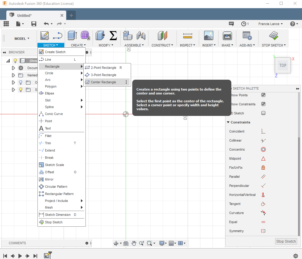
In the sketch menu, you will find several forms 2d to draw. I will start by drawing a rectangle center.
When you draw a shape, it is possible to write the measure of the sides directly in the box. You have to press TAB to change the measurement. If you draw without measure, you can use the sketch dimension tool (press D) to define a measure.
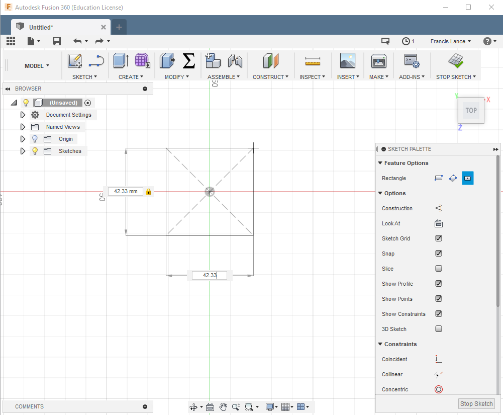
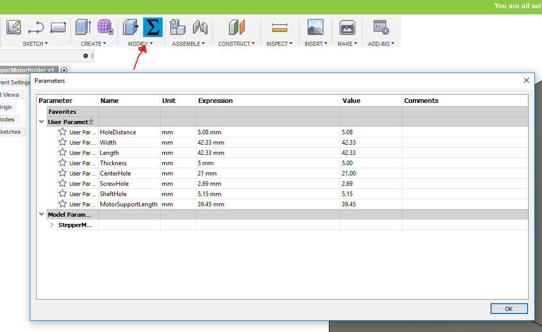
When you enter a value, it is recommended to set parameters. This is how we can edit measurements more easily in our drawings. This is called parametric drawings. You have to go to the parameters menu and define with a name a parameter and a measure.
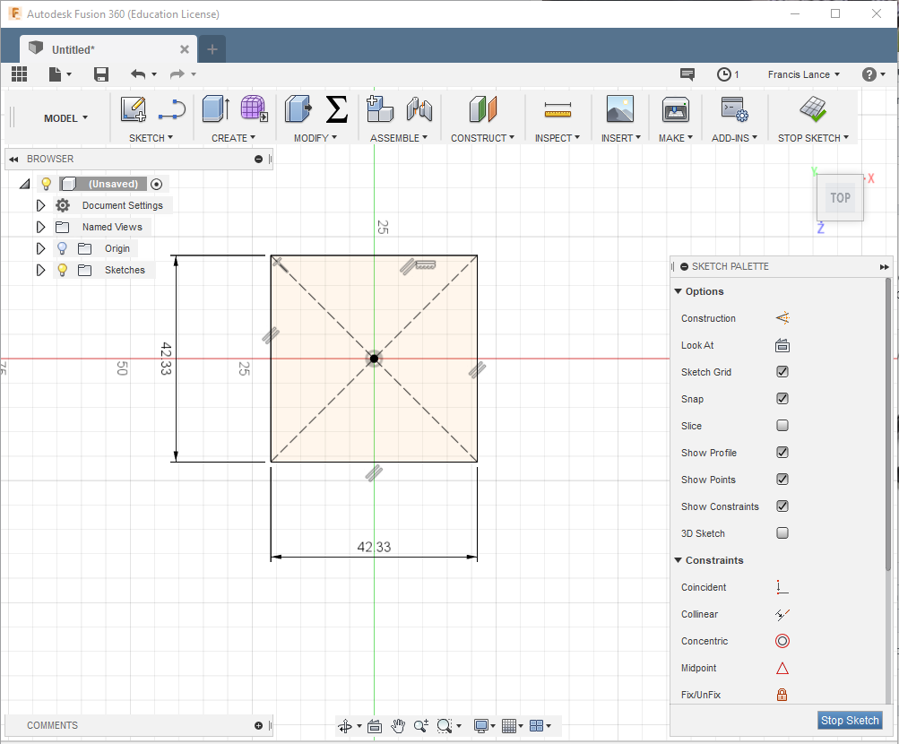
Now we have our shape defined in 2D. We are now ready to put it in 3D.
In the menu create, there are several tools to be able to work the 3D forms. The one that interests me at the moment is the extrude tools to put the 2D form in 3D.
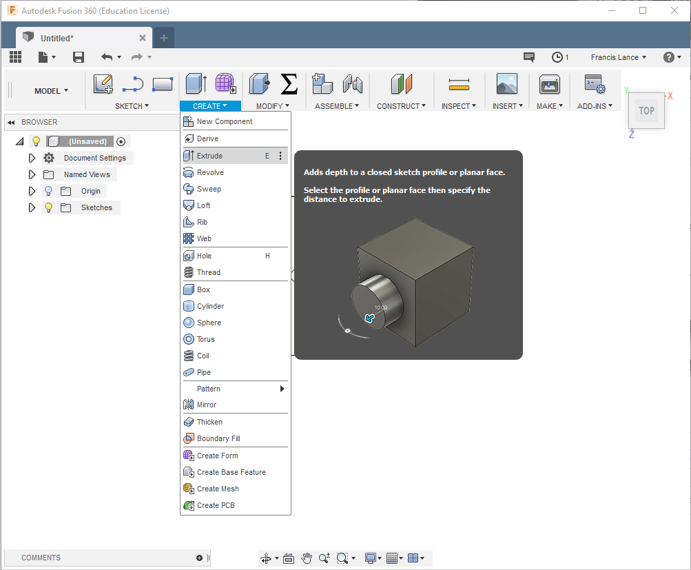
I enter the value of the thickness and I now have the shape in 3D.
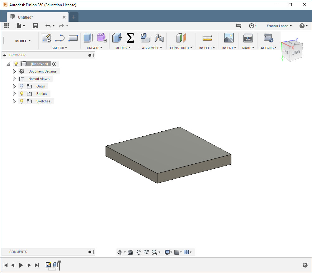
Now you have to make a small hole in the center. I will use the sketch tools to make a new plane on the part. After that, I will use the center circle tools and finally extrude the hole.
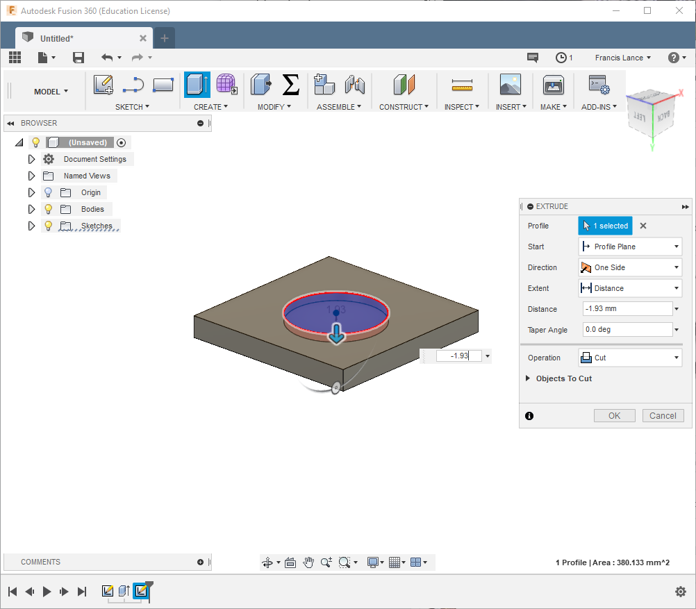
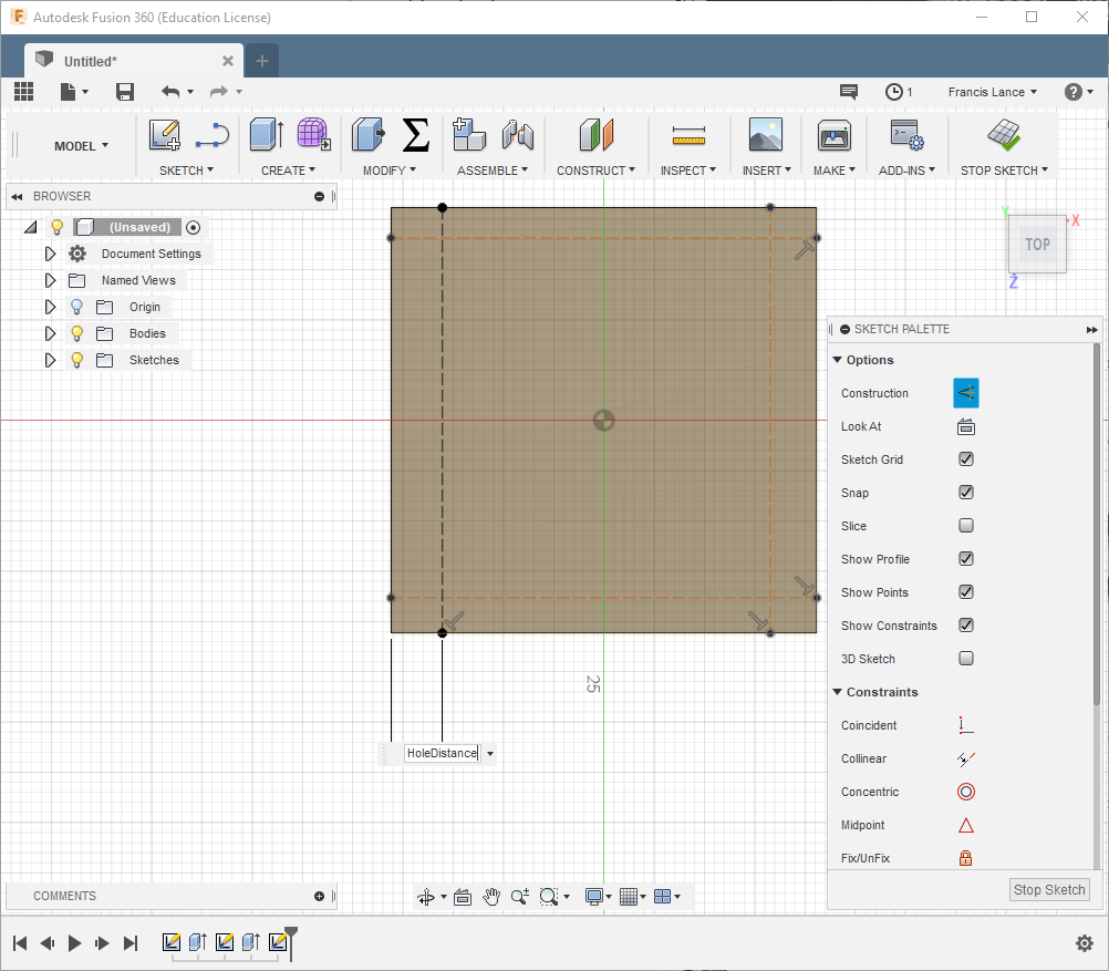
On the other side of the part, I'm going to make a new sketch to make the holes. The very useful tool is line but you have to change the type of line for a construction line in the right menu. I will use these tools to make the guide lines for my holes.
I will use the same extrude tool to make the holes.
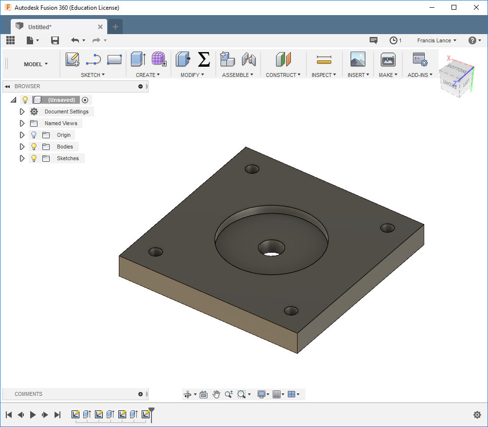
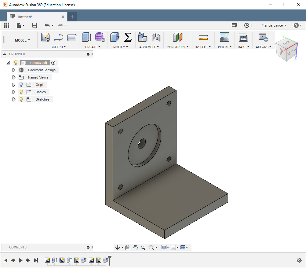
Now I will draw the part to support the stepper motor.
Here is the final part.
You can download all the files of this week right here.