#Week 09 / Embedded Programming
Research
Architecture of microcontrollers
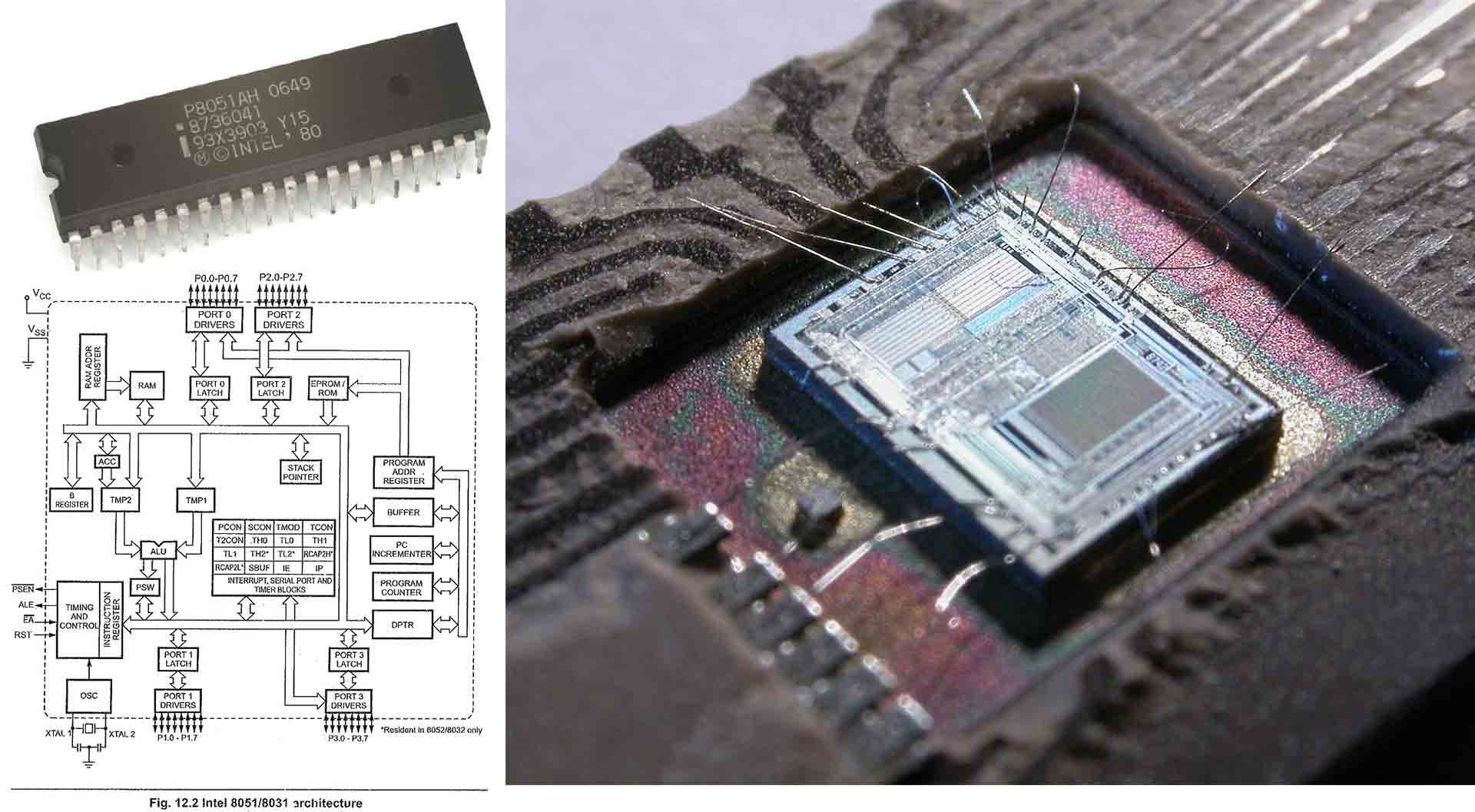
Intel 8051
The Intel MCS-51 (commonly termed 8051) is a single chip microcontroller (MCU) series developed by Intel in 1980 for use in embedded systems. The architect of the instruction set of the Intel MCS-51 was John H. Wharton.
Intel's original MCS-51 family was developed using N-type metal-oxide-semiconductor (NMOS) technology like its predecessor Intel MCS-48, but later versions, identified by a letter C in their name used complementary metal–oxide–semiconductor (CMOS) technology and consume less power than their NMOS predecessors. This made them more suitable for battery-powered devices.
Features and applications
The 8051 architecture provides many functions (central processing unit (CPU), random access memory (RAM), read-only memory (ROM), input/output (I/O), interrupt logic, timer, etc.) in one package:
- 8-bit arithmetic logic unit (ALU) and accumulator, 8-bit registers (one 16-bit register with special move instructions), 8-bit data bus and 2×16-bit address bus, program counter, data pointer, and related 8/11/16-bit operations; hence it is mainly an 8-bit microcontroller
- Boolean processor with 17 instructions, 1-bit accumulator, 32 registers (4 bit-addressable 8-bit) and up to 144 special 1 bit-addressable RAM variables (18 bit-addressable 8-bit).
- Multiply, divide and compare instructions
- 4 fast switchable register banks with 8 registers each (memory mapped)
- Fast interrupt with optional register bank switching
- Interrupts and threads with selectable priority.
- Dual 16-bit address bus; it can access 2×216 memory locations: 64 KB (65,536 locations) each of ROM (PMEM) and external RAM (XRAM)
PIC
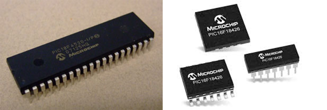
PIC (usually pronounced as "pick") is a family of microcontrollers made by Microchip Technology, derived from the PIC1650 originally developed by General Instrument's Microelectronics Division. The name PIC initially referred to Peripheral Interface Controller,then it was corrected as Programmable Intelligent Computer.
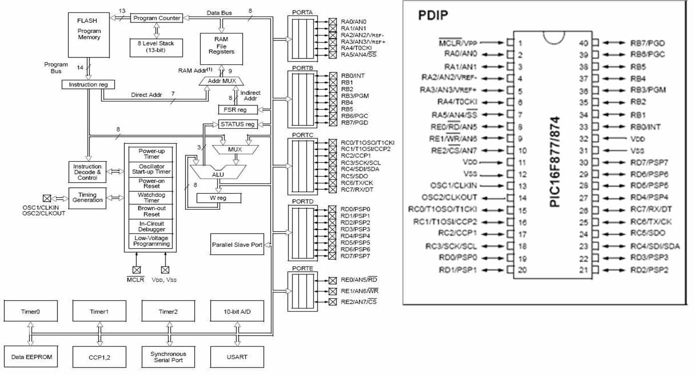
Early models of PIC had read-only memory (ROM) or field-programmable EPROM for program storage, some with provision for erasing memory. All current models use flash memory for program storage, and newer models allow the PIC to reprogram itself. Program memory and data memory are separated. Data memory is 8-bit, 16-bit, and, in latest models, 32-bit wide. Program instructions vary in bit-count by family of PIC, and may be 12, 14, 16, or 24 bits long. The instruction set also varies by model, with more powerful chips adding instructions for digital signal processing functions.
Features and applications
- PIC micro chips are designed with a Harvard architecture, and are offered in various device families.
- The baseline and mid-range families use 8-bit wide data memory, and the high-end families use 16-bit data memory.
- The latest series, PIC32MZ is a 32-bit MIPS-based microcontroller. Instruction words are in sizes of 12-bit (PIC10 and PIC12), 14-bit (PIC16) and 24-bit (PIC24 and dsPIC).
AVR
AVR is a family of microcontrollers developed since 1996 by Atmel, acquired by Microchip Technology in 2016. These are modified Harvard architecture 8-bit RISC single-chip microcontrollers. AVR was one of the first microcontroller families to use on-chip flash memory for program storage, as opposed to one-time programmable ROM, EPROM, or EEPROM used by other microcontrollers at the time.
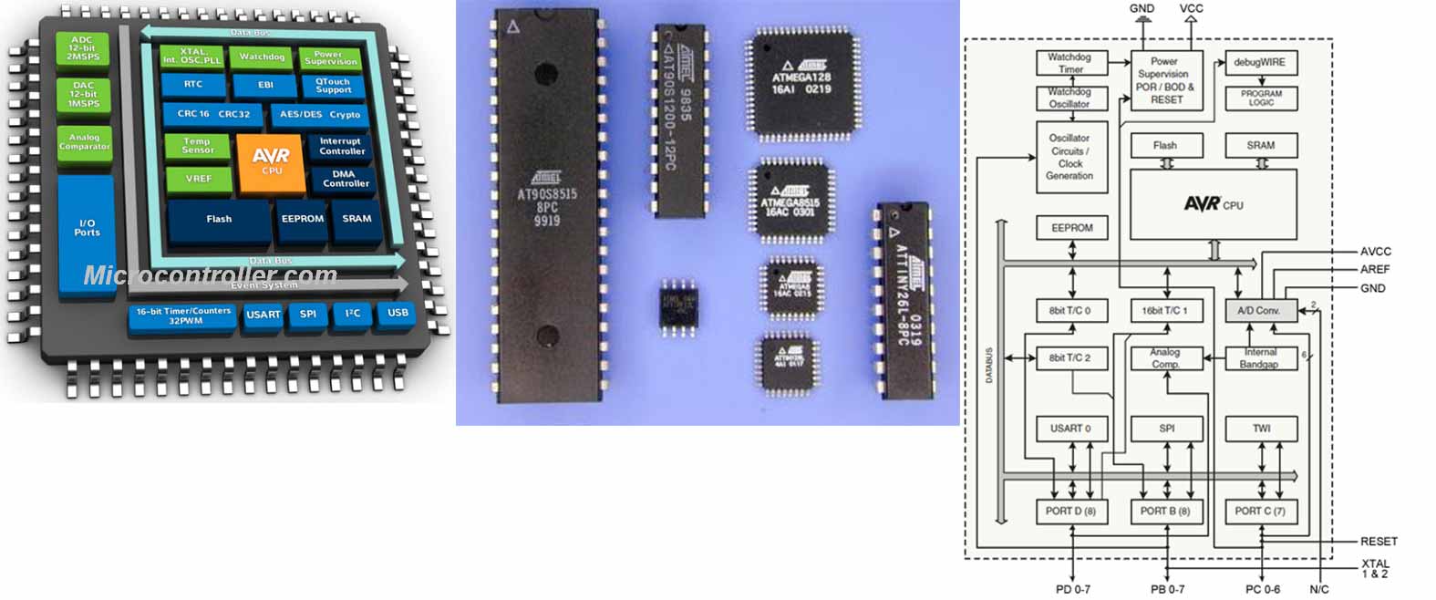
AVR microcontrollers find many applications as embedded systems. They are especially common in hobbyist and educational embedded applications, popularized by their inclusion in many of the Arduino line of open hardware development boards.
Applications
AVRs offer a wide range of features:
- Multifunction, bi-directional general-purpose I/O ports with configurable, built-in pull-up resistors
- Multiple internal oscillators, including RC oscillator without external parts
- Internal, self-programmable instruction flash memory up to 256 KB (384 KB on XMega)
- On-chip debugging (OCD) support through JTAG or debugWIRE on most devices
- External 64 KB little endian data space on certain models, including the Mega8515 and Mega162.
- 8-bit and 16-bit timers
- 10 or 12-bit A/D converters, with multiplex of up to 16 channels
- and other
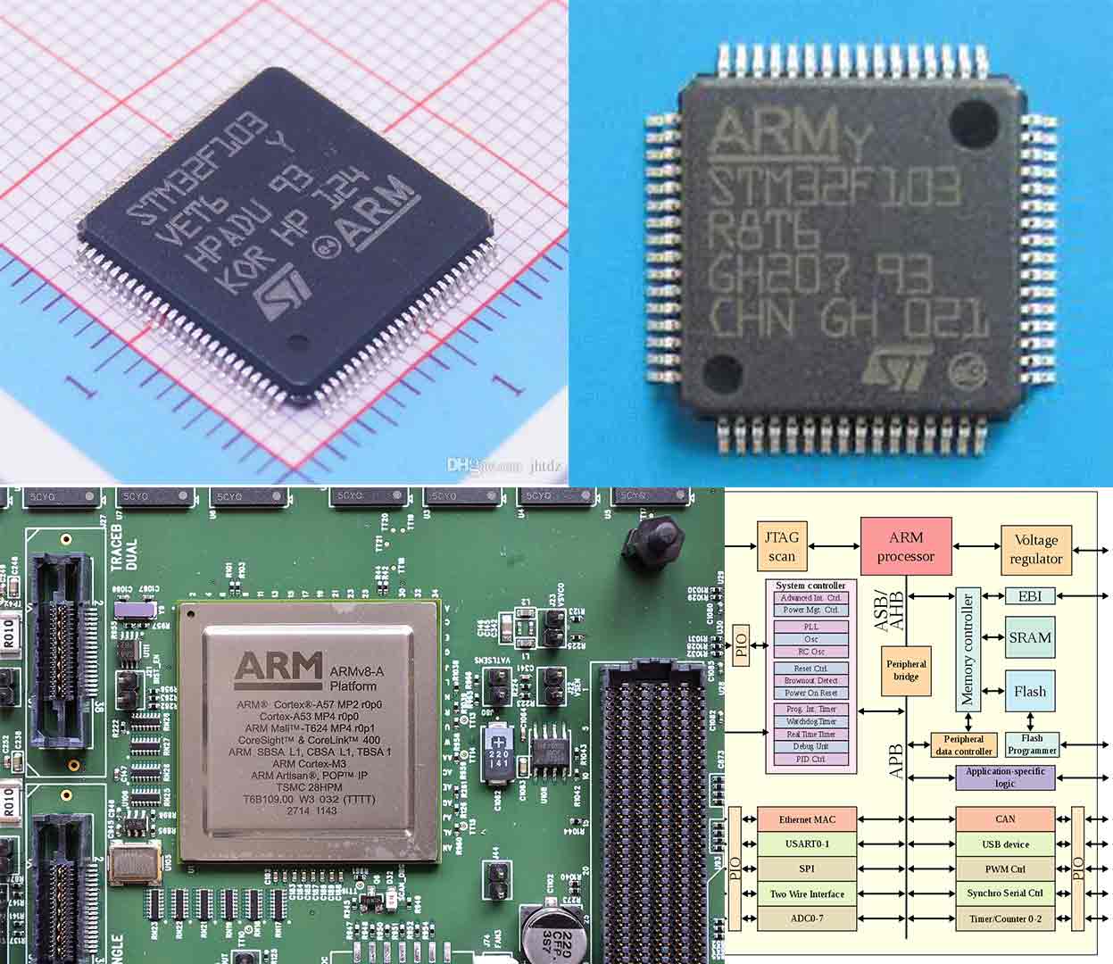
ARM
ARM, previously Advanced RISC Machine, originally Acorn RISC Machine, is a family of reduced instruction set computing (RISC) architectures for computer processors, configured for various environments. Arm Holdings develops the architecture and licenses it to other companies, who design their own products that implement one of those architectures—including systems-on-chips (SoC) and systems-on-modules (SoM) that incorporate memory, interfaces, radios, etc. It also designs cores that implement this instruction set and licenses these designs to a number of companies that incorporate those core designs into their own products.
The 32-bit ARM architecture (and the 64-bit architecture for the most part) includes the following RISC features:
- Load/store architecture.
- No support for unaligned memory accesses in the original version of the architecture. ARMv6 and later, except some microcontroller versions, support unaligned accesses for half-word and single-word load-store instructions with some limitations, such as no guaranteed atomicity.
- Uniform 16× 32-bit register file (including the program counter, stack pointer and the link register).
- Fixed instruction width of 32 bits to ease decoding and pipelining, at the cost of decreased code density. Later, the Thumb instruction set added 16-bit instructions and increased code density.
- Mostly single clock-cycle execution.
- and other
Datasheet
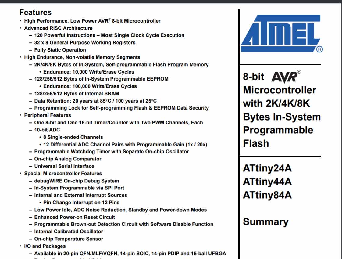
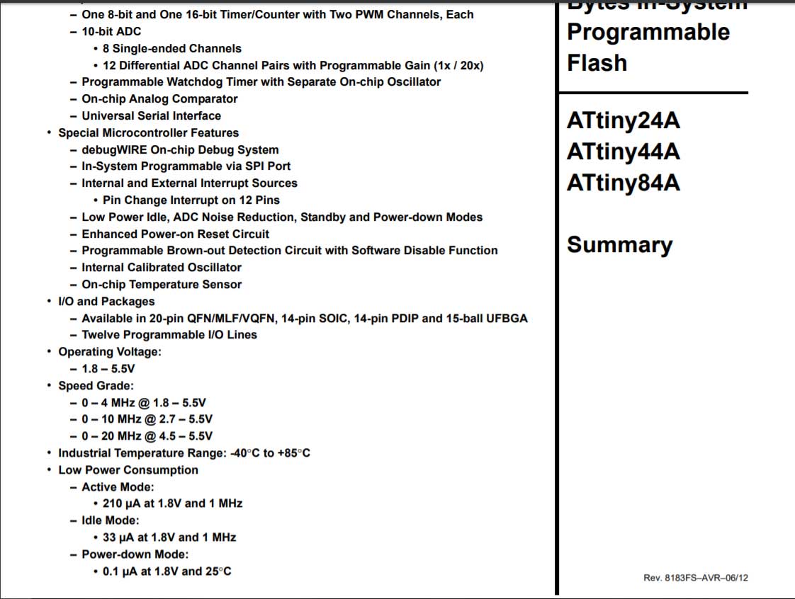
The first page of the datasheet is showing a wide variety of features that ATtiny44A has. High-Performance Low Power AVR 8-bit MIcrocontroller - it means that it has AVR architecture and 8-bit registers. 2K/4K/8K Bytes of In-system memory - It can be programmed 10000 times, and also it has 128/256/512 Bytes In-System EEPROM type memory - It can be programmed 100000 times. It has 8-bit 16-bit time counter, 10-bit ADC, Watchdog timer, Analog Comparator, Debug System, In-System Prog. via SPI port, On-chip temperature sensor. Voltage 1.8-5.5V .0-20 MHz (4.5-5.5V).
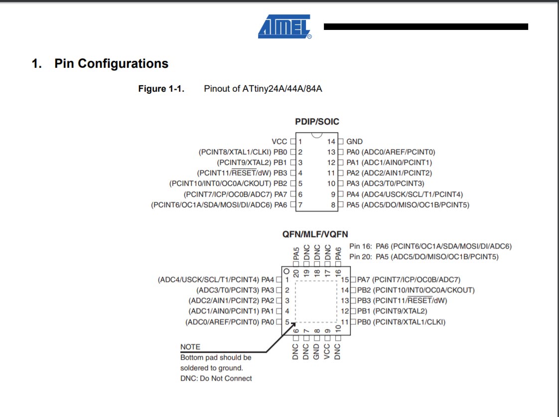
One of the most important things in the datasheet is Pin configuration. ATtiny44A has VCC(1) and GND(14) ports for power, PB0(2) and PB1(3) is for crystal (20.000 MHz), Reset pin PB3(4), programming pins PA4(9) SCL-clock, PA5(8) MISO, PA6(7) MOSI, other ports can be configured ass ADC, Input, output(I/0) and other .
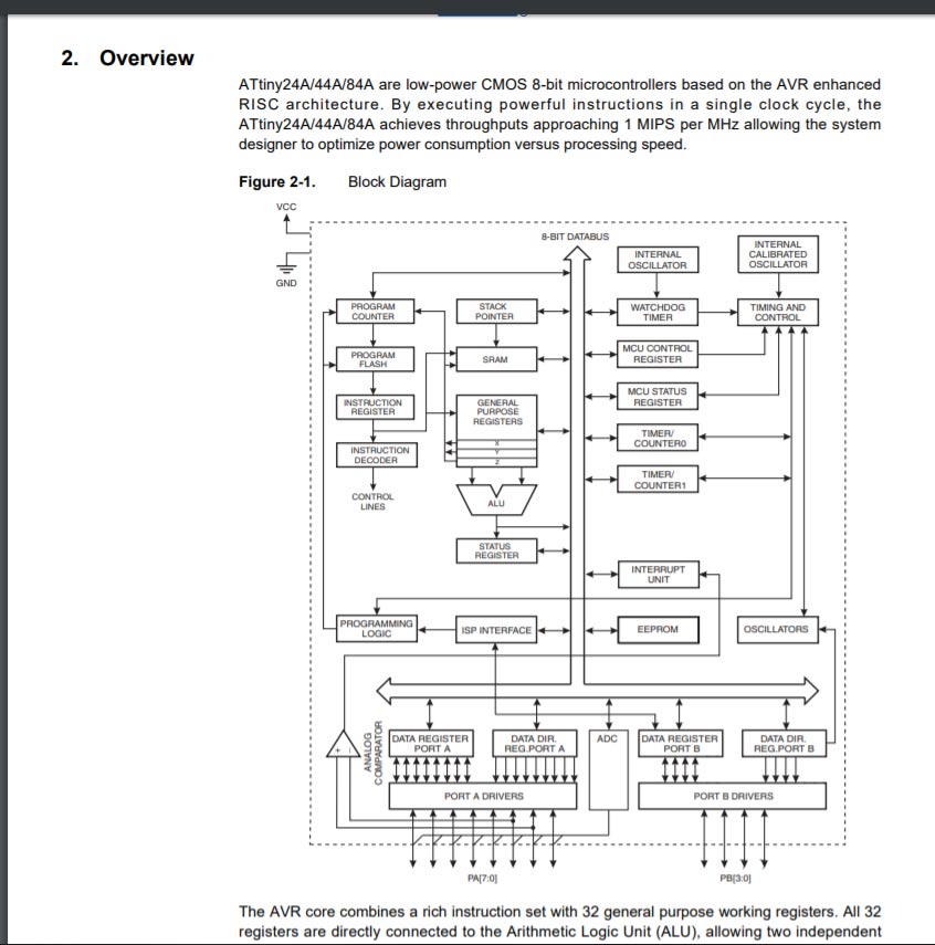
In the block diagram of the controller, you can see the architecture of the controller. Each block has its function.
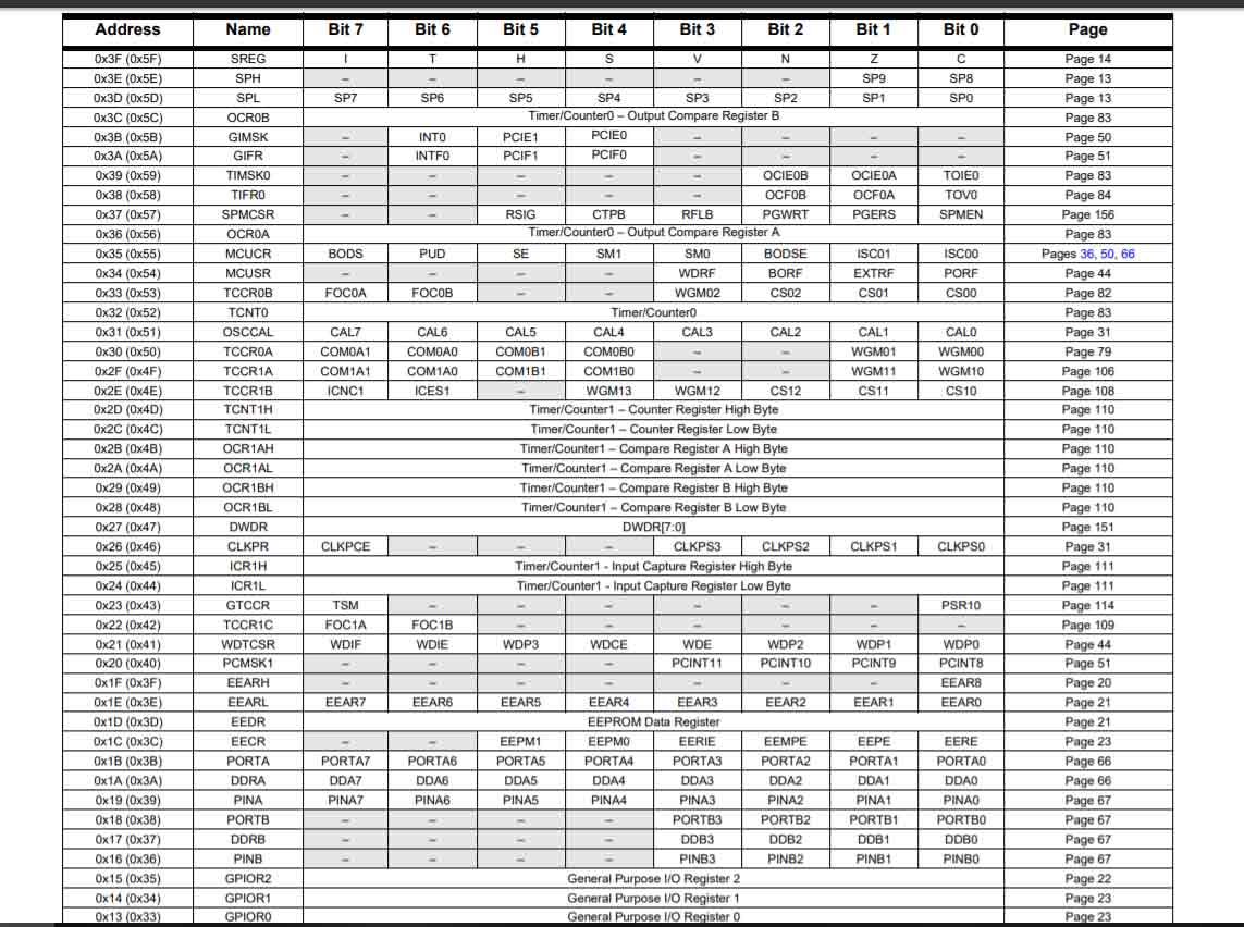
Here you can see all register. Each block in the block diagram is constructed by these registers which you can program individually using assembly language.
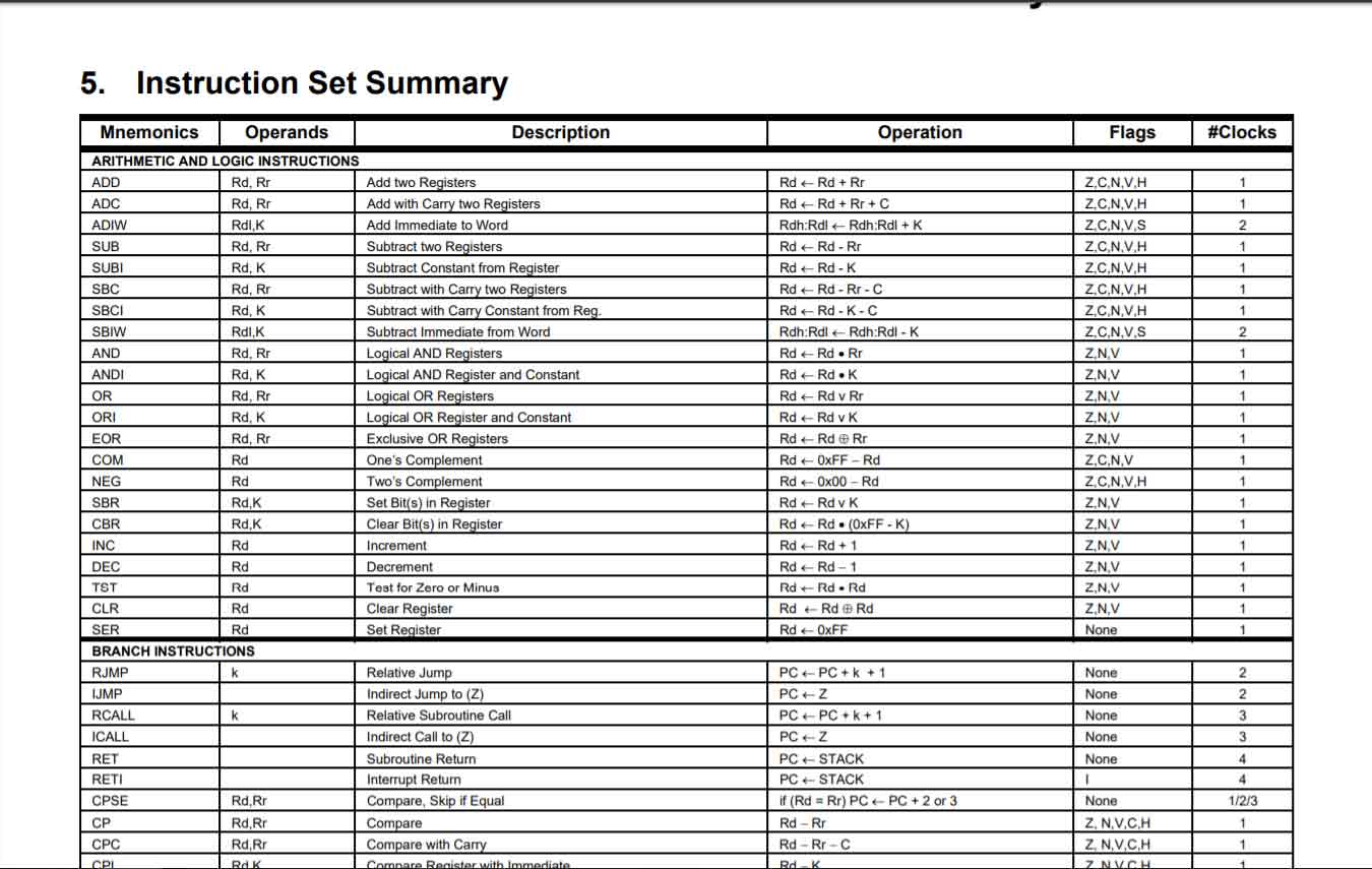
Instruction Set Summary is a basic command that can be used for programming your controller, by signing register individually.
Here you can see all versions of Attiny44A, Functionality is the same for all of them , the only differences are package and temperature range. Also the differences between ATtint24A, ATtint44A and ATtint84A is the size of memory.
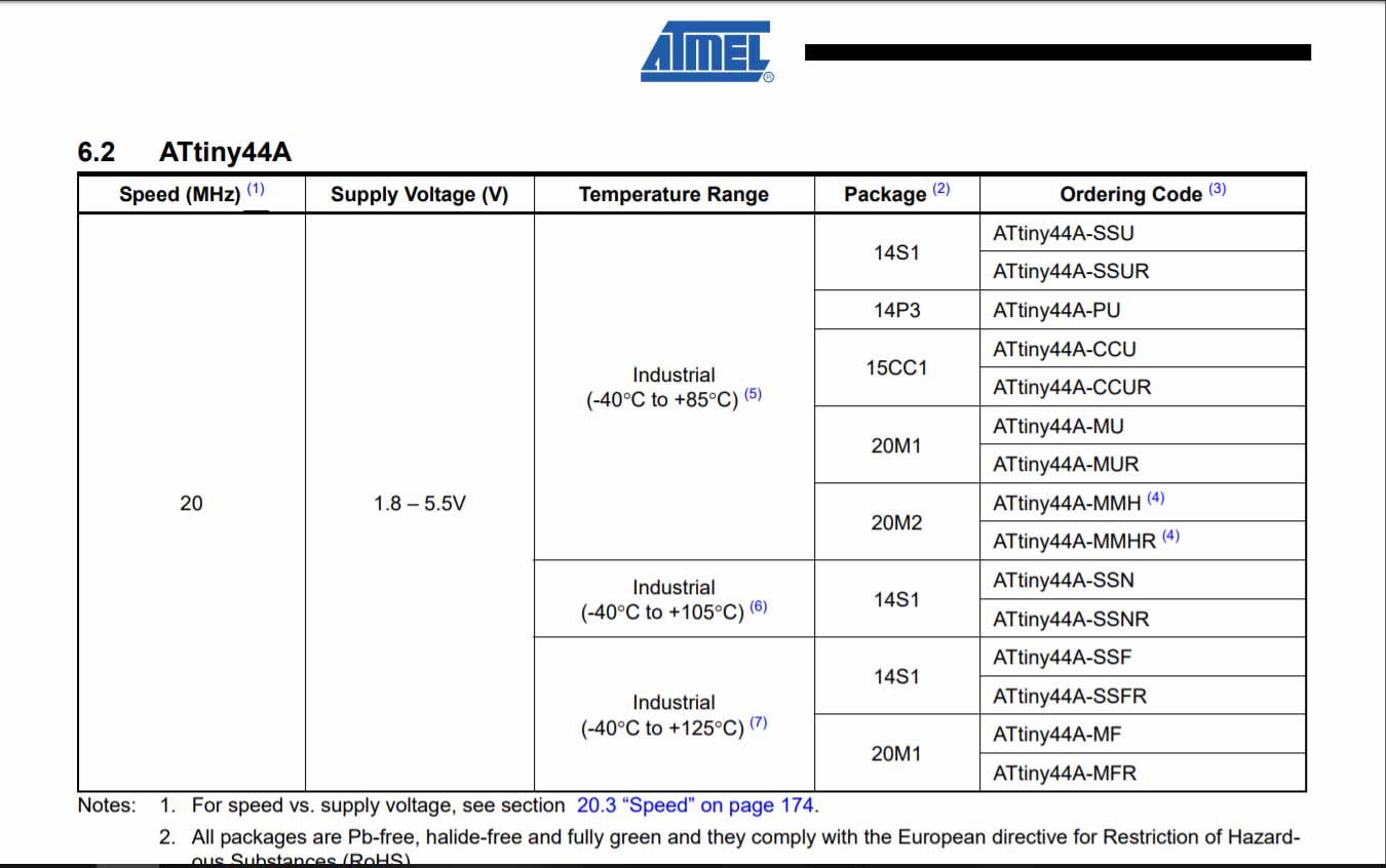
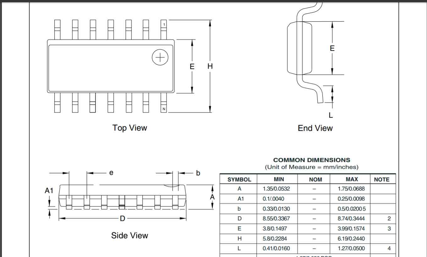
This is the package of the ATtiny -44A-SSU(14S1).
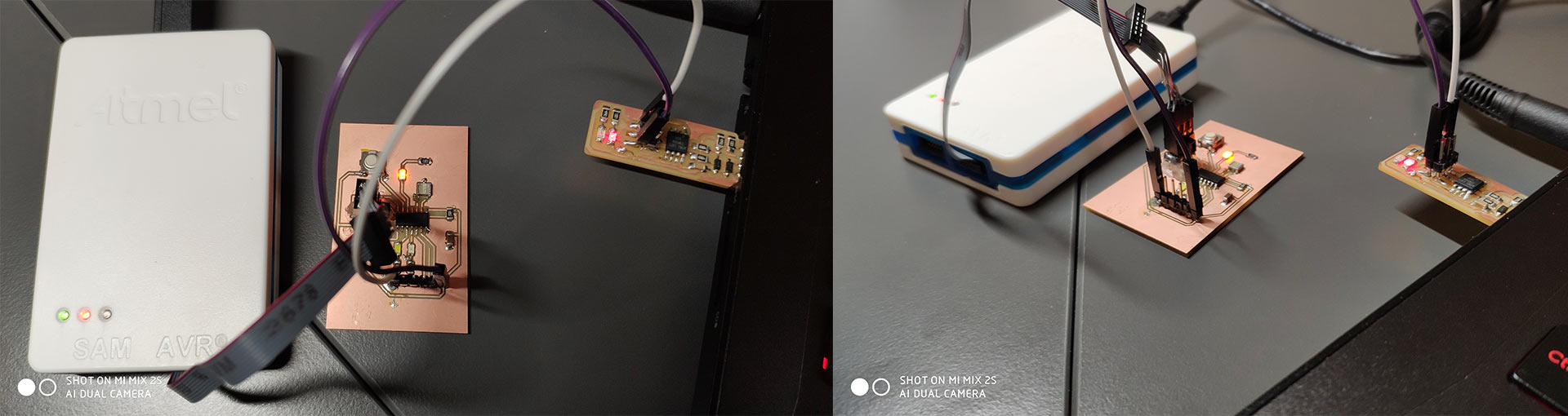
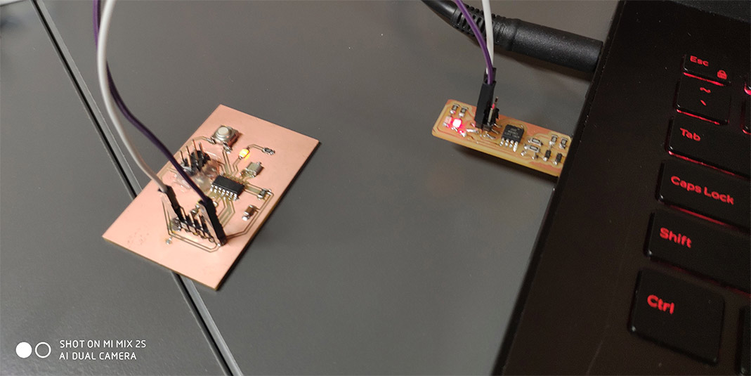
Programming
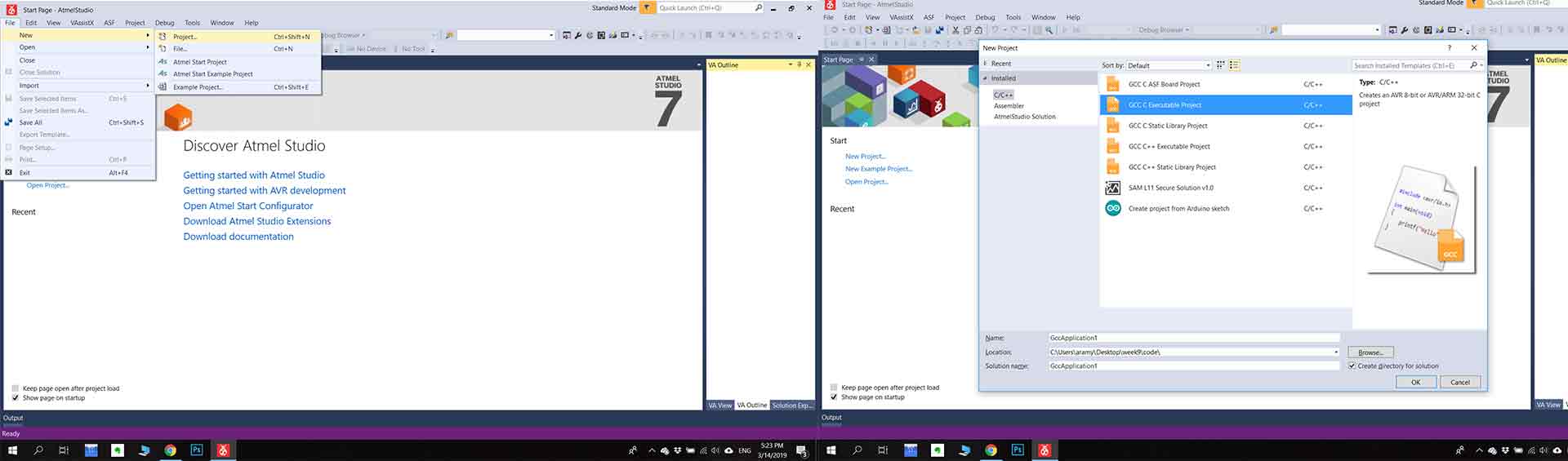
Before starting you need to download the Atmel Studio (I used Atmel Studio 7th version). After downloading if you want to create a new project you need to go “File > New > Project ” and choose “GCC C Executable Project C/C++ " if you want to write your code on C language(also you can choose the location for saving all file , and also the name of the project ). After you must choose microcontroller (In my case it is ATtiny -44A ).And finally it will open .c folder, and you can start write your code. In my code
I write that whenever I press the button it will decrease the frequency of blinking, and after some time I will back to a common frequency. First I added the libraries #include avr/io.h> and #include util/delay.h> .
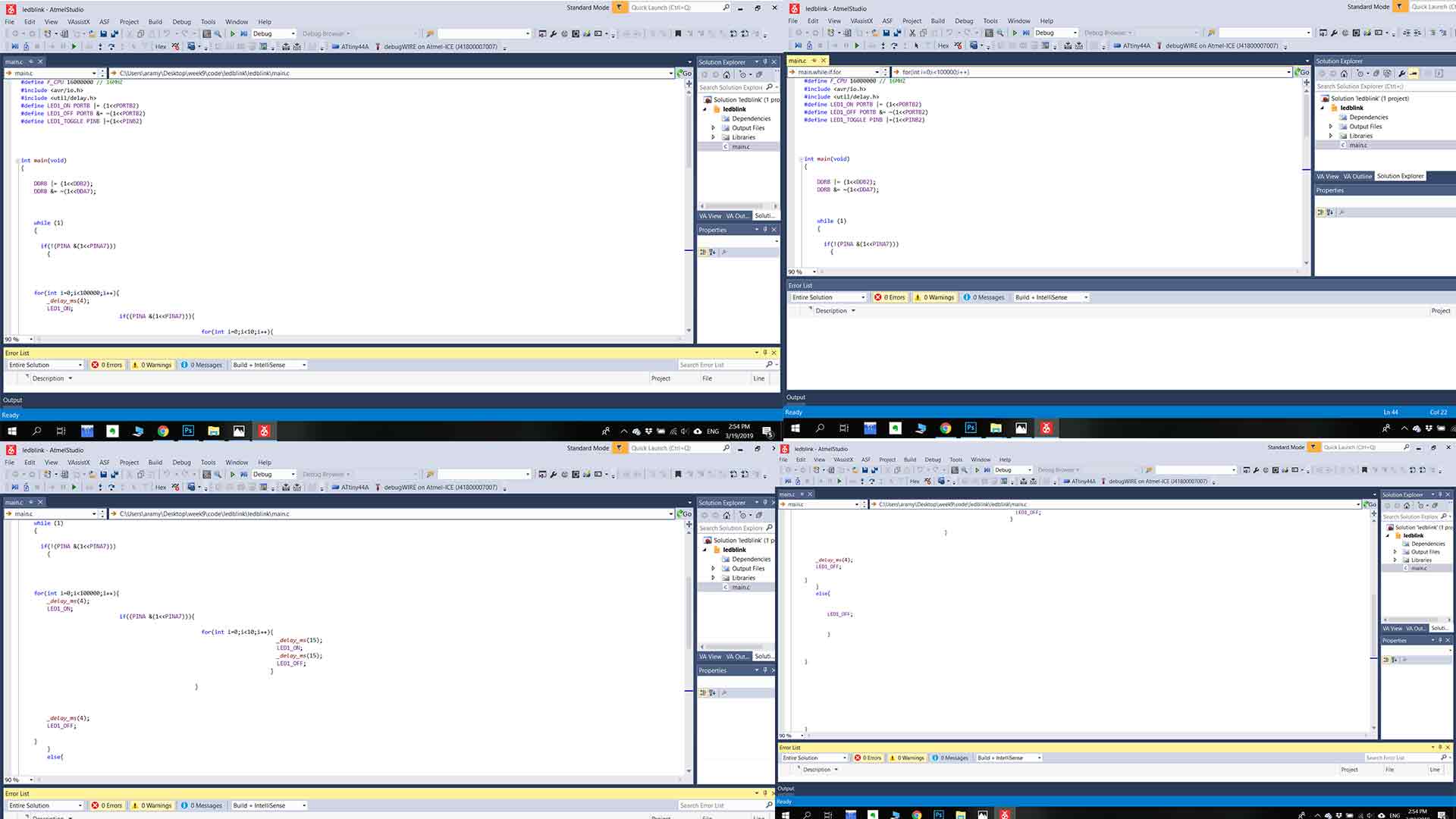
After I defined the Led_on and Led_off functions and add it in the main function (the main function is the point where the code starts to run ). I added infinite while loop while(1){ } it means whenever code enters while loop it will never go out of that loop (besides if there are no brack or goto functions ) . If statement says that if condition is true go inside brackets If(condition){inside brackets} , condition is pressed button .Inside brackets, I write for loop inside for loop is if, the condition of if statement is press button (if the button is press the frequency will be changed).
Code
This code does - changing the frequency of blinking LED whenever you press the button.This code is written on C language.
#define F_CPU 16000000 // 16MHZ
#include
#include
#define LED1_ON PORTB |= (1 << PORTB2)
#define LED1_OFF PORTB &= ~(1 << PORTB2)
#define LED1_TOGGLE PINB |=(1<< PINB2)

int main(void)
{
DDRB |= (1 << DDB2);
DDRB &= ~(1 << DDA7);

while (1)
{

if(!(PINA &(1<< PINA7)))
{


for(int i=0;i<100000;i++){
_delay_ms(4)
_LED1_ON;

 if((PINA &(1 << PINA7))){

 for(int i=0;i < 10;i++){

 _delay_ms(15);

 LED1_ON;

_delay_ms(15);

LED1_OFF;

}


}

  >