#Week 15 / Mechanical Design, Machine Design
Assignment and learning outcomes.
What is this week assignment?
Group assignment Mechanical Design (part 1 of 2)- Design a machine (mechanism + actuation + automation), build the mechanical parts and operate it manually, document the group project. As an individual assignment- Document your individual contribution.
Group assignment Mechanical Design (part 2 of 2)- Actuate and automate your machine, document the group project. Individual assignment- Document your individual contribution.
Leraning outcomes
Introduction
For Mechanical Design and Machine Design weeks, we decided to make a camera control machine. With this machine, we can adjust focus(for macro cameras) of the camera, and also shot videos in motion with other moving objects. The main problem that our macro camera is have manual focus mechanism. With this mechanism is very hard to get the right focus. We what to solve this problem by making automated camera control machine. Before starting this group project, first of all, we need to make a plane. We make tasks for each of as and divided them. Hear is dashboard
This all task are made to increase the effectiveness of the process, but everything we have done as a group by helping each other and solving problems together, we have done quite much everything together.
Computer-Aided Design
Introduction to 2D modeling
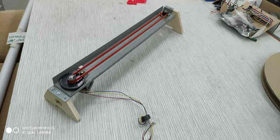
For the machine, I need to design legs for the rail of the machine. For this purpose, I used Vcarve Pro which very easy to use for simple applications also you can generate g code for ShopBot directly from softer by choosing parameters for the toolpath. I have drow simple 2D sketch for legs in rectangular forms with the hole in the middle. I drow 2 rectangular legs with different heights(because of different highs at ends of rail). After drawing I generated the toolpath and start cutting.
Process
To start drawing in Vcarve Pro first you need Click on "Create a new file " after opening the program to create a new file. After opening the file save it somewhere and after that we can start drawing. The first thing that you need to do before the actual drawing is to navigate to "File Operations" and click to "Job setup", here you need to set up your material dimensions
After setting up dimensions of material now we need to drow 2D sketch for legs, for that, I used these tools


you can find all these tools on the left side on the sidebar. After sketching 2D model of our legs, we need to generate toolpath, to generate toolpath we need to click on an icon on the right side and choose "2D Profile Toolpath" for rectangular holes in the middle. First, need to click on vector and after adjust parameters

Machine parameters
By choosing a tool, you and change parameters like Tool Type, Diameter, Pass Depth, Stepover, Spindel Speed (r.p.m), Feed Rate, Plunge Rate(inches.sec) in my case I chouse


Also, I have added passes from 4 to 7(just for safety). After adjusting all parameters press calculate and observe 3D visualization on toolpath by using "Preview Toolpaths" tool in the Toolpaths section. After checking , go "Save toolpathes" and save the file somewhere by clicking "Save Toolpathes(s) to File"(it will generate g code for shopbot ). The same process is required to cut out(pocket).

Introduction to 3D modeling
As a 3D model, Mariam needs to design a holder for a camera that fits on the rail. The modeling of this part is very challenging because it has a complex structure. But by using Fusion 360 is very easy to drow and get the right design. Fusion 360 is an integrated CAD, CAM, and CAE software. It simplifies your entire workflow with one unified platform. Also, Fusion 360 has

The main process in 3D modeling is to draw 2D sketch and turn the 2D sketch into a 3D object by expanding it from the plane. Also by using the diferent tool you shape or modify your object 3D model. Before starting modeling we need to measurements from the rail. The main tools that have been used for modeling are


Computer-Controlled Machining(ShopBot)
Introduction
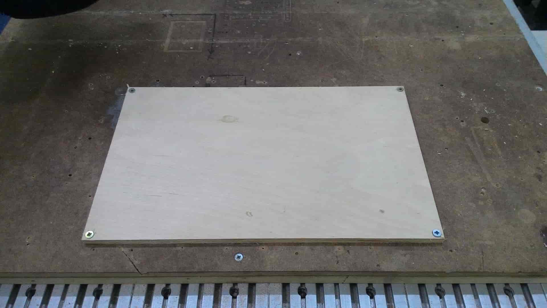
For cutting the legs we have used ShopBot Desktop MAX because we need to cut small part, and we decided to cut it on a smaller shopbot.
Process
After generating all files you must fit the material on shopbot surface and 0 the axis(X ,Y ,Z) of ShopBot .Just Simply go to at the position where you what to 0 X, Y and 0 it, for the Z axis you can use z zero plate. After 0 all axis and having all files, you can cut by pressing Cut Part(make sure your tool is near to zeroed axis) Press Start button on the remote controller and it will start cutting (Make sure your dust collector is turned on before starting cutting). After its finish remove the material (make sure that key is turned clockwise ), and measure it. Here is steps to follow
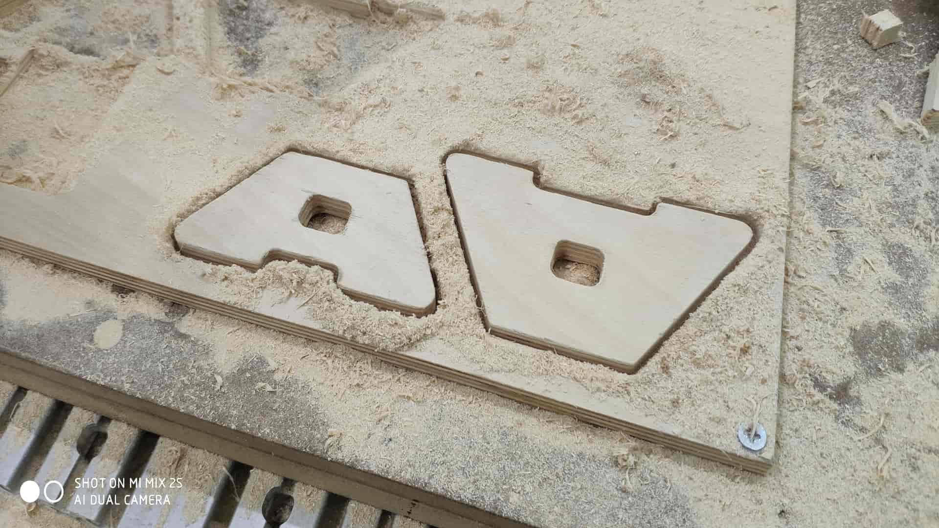
In any case if you cut MDF be carryful- When MDF or other wood sheet is cut, a large number of dust particles are released into the air. It's important a respirator is worn and that the material is cut in a controlled and ventilated environment. It's good practice to seal exposed edges to limit emissions from binders contained in this material. So I turned on vacuum cleaner when I started to cut MDF.
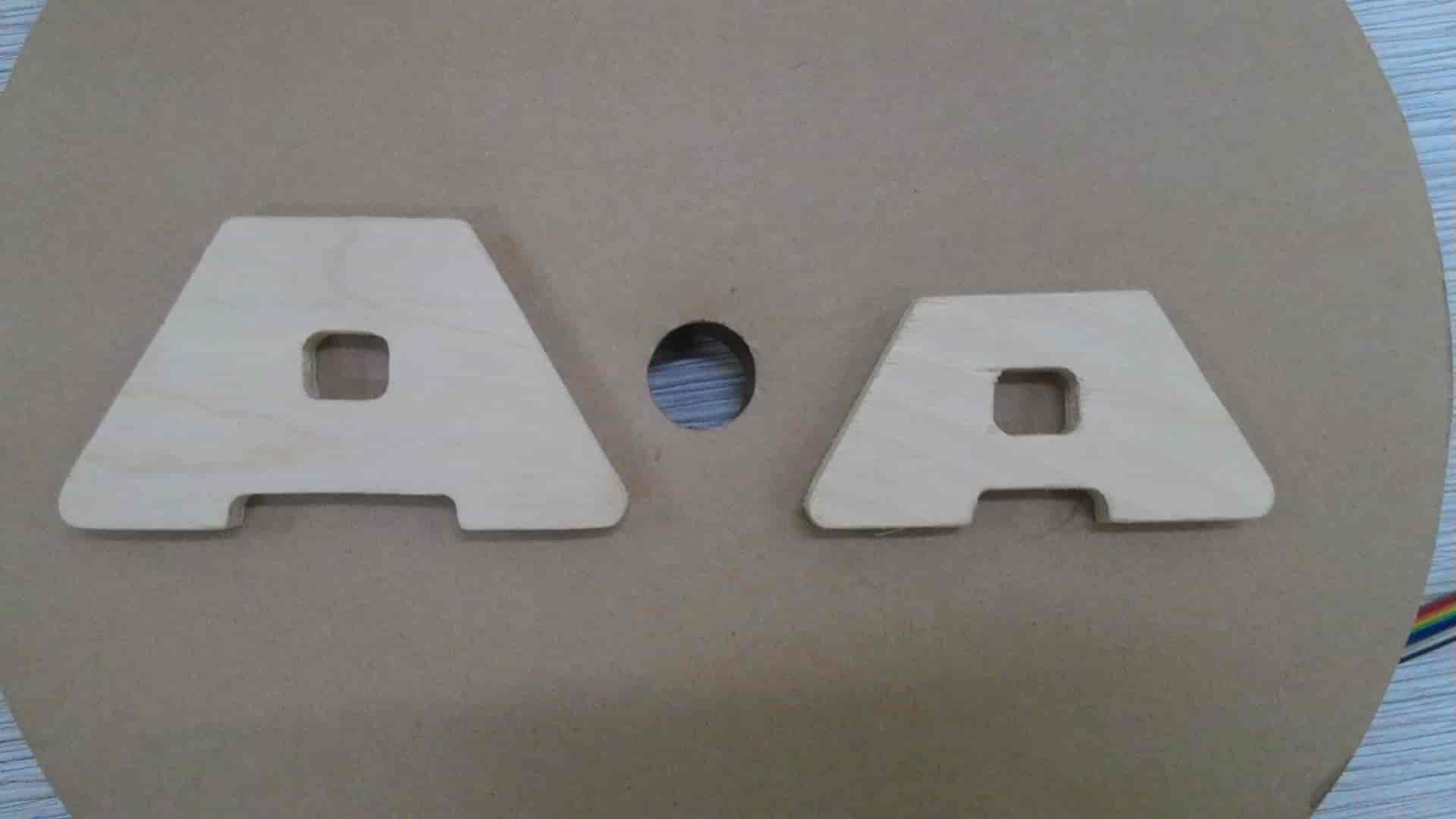
Main paramets for Plywood cutting with 1/8 inch mill
3D printing
Introduction
For 3D printing, we have used Ultimaker Extended 2 Plus. This 3D printer delivers robust single extrusion 3D printing. It is affordable, reliable, and user-friendly, the Ultimaker 2 Extended+ deliver consistent results – suitable for rapid prototyping and concept models. They feature swappable nozzles, a heated glass build plate, and an open filament system.

First, we export our 3D model in .stl file format an imported it in "Cura" softer which is support Ultimaker printers. We have adjusted the position of the model to apply for less support. We have used custom settings


Ultimaker 2 Extended+ has: 228.6 x 226.06 x 304.8mm Build Volume Easily switch between 0.25, 0.40, 0.60 and 0.80 mm nozzles It prints ABS, PLA, HIPS, PET, ColorFabb XT, ColorFabb XT-Carbon Fibre, Woodfill, Bronzefill, Copperfill, Brassfill and flexible materials such as PolyFlex and Ninjaflex Requires 2.85mm filament.

Electronics Production
Electronics Design
As board for our project, we choose to use Babken's board that he designed for the final project because it has all functions to run our machine. To check out the board go to Babken website serch in final project. Also we have added remote conntroll for Machine.

Fab ISP
For programming the board we used FabISPFabtinyISP is a 100% fabable ISP (In System Programmer) based on the FabTinyStar board, which was specificly designed to be made in a FabLab. FabTinyISP enables microcontrollers to be programmed while installed in a complete system, rather than requiring the chip to be programmed prior to installing it into the system. In other words it allows us to program microcontrollers on other boards we make. I recommend to read this paper Demystifying the FabISP before making the ISP In System Programmer, where you can learn in detail the purpose of each component on the board. Here are some points that I belive are essential:
SRM-20
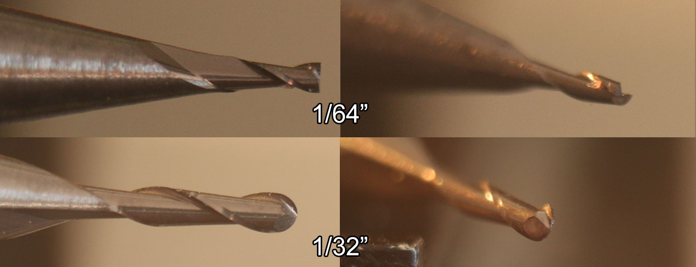
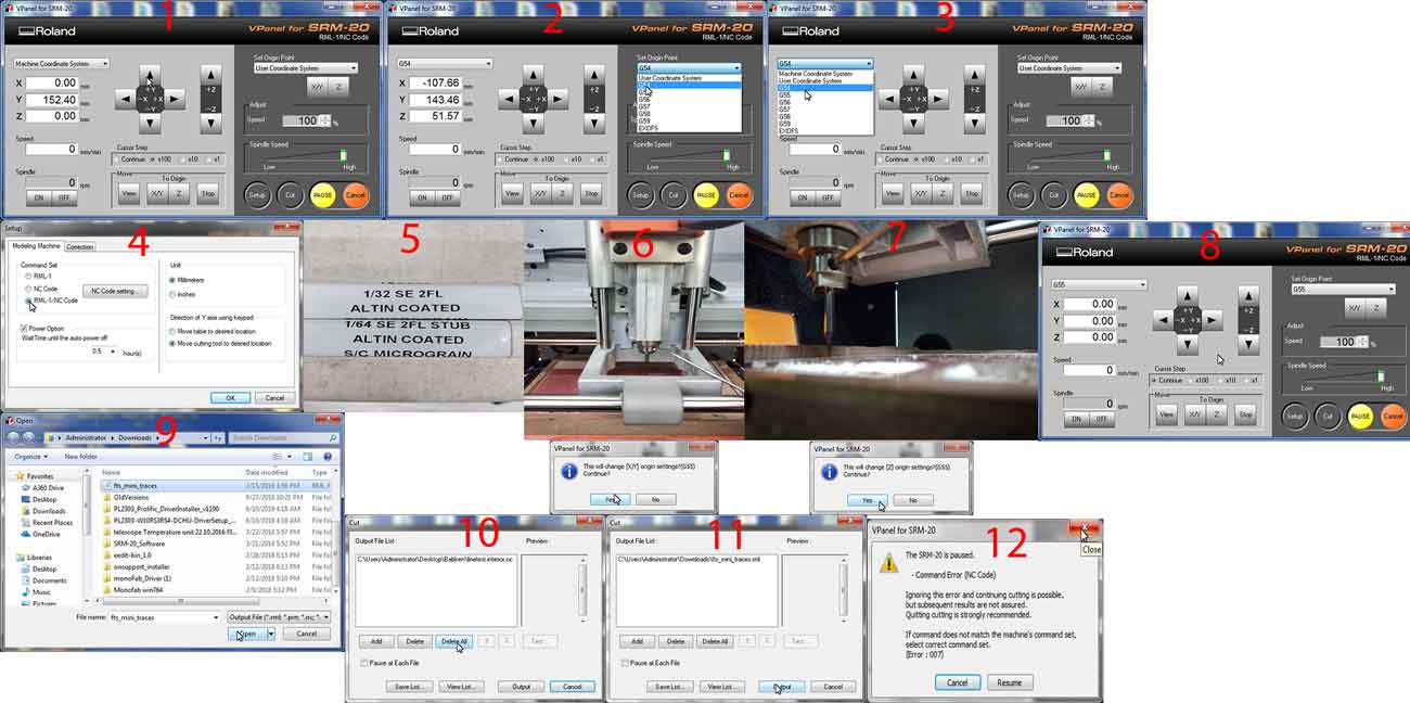
We will mill the Printed circuit board and solder the componets. The milling machine that we'll use is Roland-monoFab SRM-20 you can find it's manual here. We teamed up with Miqael to explore our machine and to mill the recommended linetest pattern and it's cutout. We used 1/64in(0.4mm) endmill for milling the PCB traces and 1/32in endmill to cut out the PCB from the base material in our case FR-1.Setting up the Machine

G code generation
In our case the cut files are FabtinyISP traces and FabtinyISP cutout. The toolpath is the path that our bit has to travel in order to get the desired geometry on the base material. In order to generate the "toolpath" we'll be using FabModules (image below). And after generating the toolpath we'll save it as a NC code (G-code) for the machine to understand it. Select the input file from "input format" tab, select the output from "output format" tab in our case it's G-codes (.nc) and fianlly select the tool size from the "process" tab in our case it's PCB traces (1/64).
At this point an image should appear under the selection we just did and a detailed settings on the right side. (image below). In "output" section you can set the
Open the V-panel make sure the 1/64 endmill is on the tool and is zeroed. Push the "cut" button from the interface hit "Delete all" to remove previous NC codes, now select the NC file you generated for the traces it's name should be "fts_mini_traces.nc" Change the speed value to 10 at the start of the cutting in order to have more time to react if something goes wrong. If everything is ok increase the speed to 100.
Soldering
Before starting soldering clean up the space around and make sure you have all supplys.
also all components for Machine board
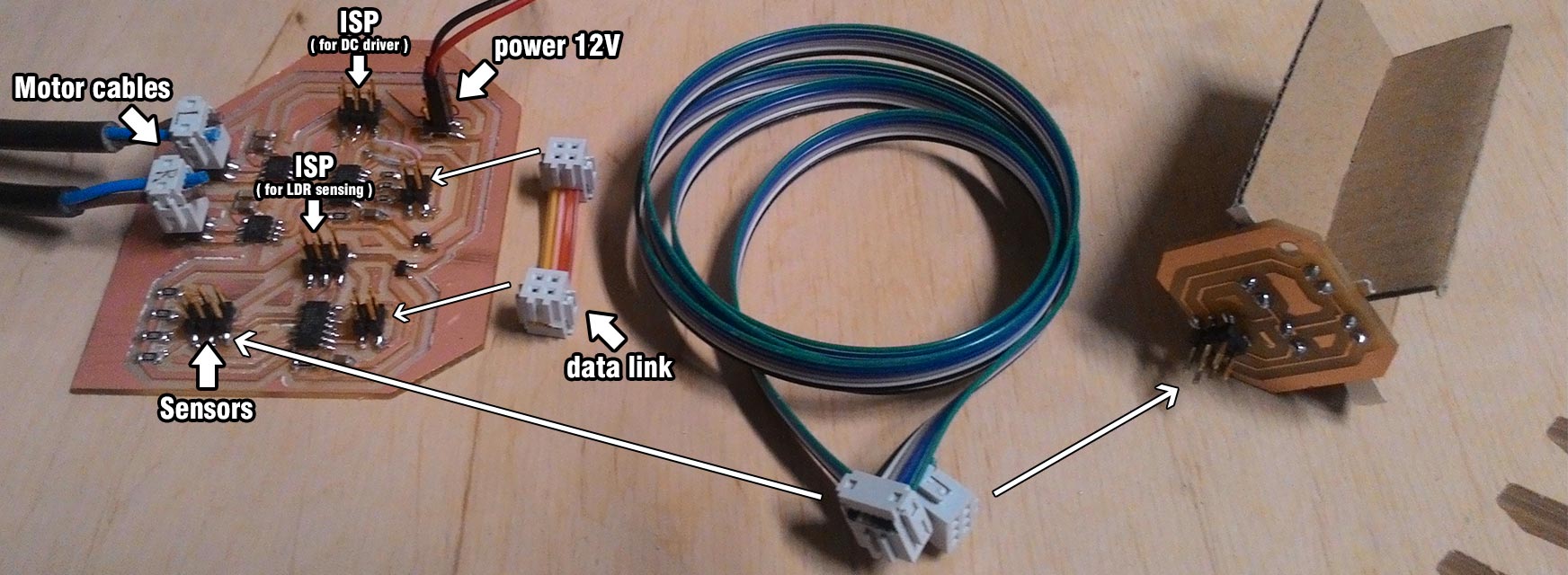
Remove unnecessary parts on the board with cutter .Clean up your PCB with water . Water the soldering iron sponge .Start Soldering(Solder by looking on schematics and layout .I added a jumper , after programming you can put it in one pin )
Code
		//
		//
		// machine.44.c
		//
		// //
		// Babken Chugaszyan
		// 06/01/19
		//
		// This work may be reproduced, modified, distributed,
		// performed, and displayed for any purpose. Copyright is
		// retained and must be preserved. The work is provided
		// as is; no warranty is provided, and users accept all
		// liability.
		//

		#include
		#include

		#define output(directions,pin) (directions |= pin) // set port direction for output
		#define input(directions,pin) (directions &= (~pin)) // set port direction for input
		#define set(port,pin) (port |= pin) // set port pin
		#define clear(port,pin) (port &= (~pin)) // clear port pin
		#define pin_test(pins,pin) (pins & pin) // test for port pin
		#define bit_test(byte,bit) (byte & (1 << bit)) // test for bit set


		#define input_port PORTB
		#define input_direction DDRB
		#define input_pino (1 << PB0)//button
		#define input_pini (1 << PB2)//button
		#define input_pinu (1 << PB1)//button
		#define input_pins PINB


		#define bridge_port PORTA // H-bridge port
		#define bridge_direction DDRA // H-bridge direction
		#define A2 (1 << PA0) // H-bridge output pins
		#define A1 (1 << PA1) // "
		#define B2 (1 << PA3) // "
		#define B1 (1 << PA4) // "
		#define on_delay() _delay_us(25) // PWM on time
		#define off_delay() _delay_us(5) // PWM off time
		#define PWM_count 50 // number of PWM cycles
		#define step_count 20 // number of steps

		static uint8_t count;

		//
		// A+ B+ PWM pulse
		//
		void pulse_ApBp() {
		  clear(bridge_port, A2);
		  clear(bridge_port, B2);
		  set(bridge_port, A1);
		  set(bridge_port, B1);
		   for (count = 0; count < PWM_count; ++count) {
			  set(bridge_port, A1);
			  set(bridge_port, B1);
			  on_delay();
			  clear(bridge_port, A1);
			  clear(bridge_port, B1);
			  off_delay();
			  }
		   }
		//
		// A+ B- PWM pulse
		//
		void pulse_ApBm() {
		  clear(bridge_port, A2);
		  clear(bridge_port, B1);
		  set(bridge_port, A1);
		  set(bridge_port, B2);
		   for (count = 0; count < PWM_count; ++count) {
			  set(bridge_port, A1);
			  set(bridge_port, B2);
			  on_delay();
			  clear(bridge_port, A1);
			  clear(bridge_port, B2);
			  off_delay();
			  }
		   }
		//
		// A- B+ PWM pulse
		//
		void pulse_AmBp() {
		  clear(bridge_port, A1);
		  clear(bridge_port, B2);
		  set(bridge_port, A2);
		  set(bridge_port, B1);
		   for (count = 0; count < PWM_count; ++count) {
			  set(bridge_port, A2);
			  set(bridge_port, B1);
			  on_delay();
			  clear(bridge_port, A2);
			  clear(bridge_port, B1);
			  off_delay();
			  }
		   }
		//
		// A- B- PWM pulse
		//
		void pulse_AmBm() {
		  clear(bridge_port, A1);
		  clear(bridge_port, B1);
		  set(bridge_port, A2);
		  set(bridge_port, B2);
		   for (count = 0; count < PWM_count; ++count) {
			  set(bridge_port, A2);
			  set(bridge_port, B2);
			  on_delay();
			  clear(bridge_port, A2);
			  clear(bridge_port, B2);
			  off_delay();
			  }
		   }
		//
		// clockwise step
		//
		void step_cw() {
		   pulse_ApBp();
		   pulse_AmBp();
		   pulse_AmBm();
		   pulse_ApBm();
		   }
		//
		// counter-clockwise step
		//
		void step_ccw() {
		   pulse_ApBm();
		   pulse_AmBm();
		   pulse_AmBp();
		   pulse_ApBp();
		   }

		int main(void) {
		   //
		   // main
		   //

		   //
		   // set clock divider to /1
		   //
		   CLKPR = (1 << CLKPCE);
		   CLKPR = (0 << CLKPS3) | (0 << CLKPS2) | (0 << CLKPS1) | (0 << CLKPS0);
		   //
		   // initialize bridge pins
		   //
		   clear(bridge_port, A1);
		   output(bridge_direction, A1);
		   clear(bridge_port, A2);
		   output(bridge_direction, A2);
		   clear(bridge_port, B1);
		   output(bridge_direction, B1);
		   clear(bridge_port, B2);
		   output(bridge_direction, B2);

		   set(input_port, input_pino); // turn on pull-up
		   set(input_port, input_pini);
		   set(input_port, input_pinu);

		   input(input_direction, input_pino);
		   input(input_direction, input_pini);
		   input(input_direction, input_pinu);

		   //
		   // main loop
		   //
		   while (1) {
			  int a=0;
			   if (0 == pin_test(input_pins,input_pino))
			  {if (0 == pin_test(input_pins,input_pinu)){
			  for (a=0; a<50; a++){
			  step_cw();}
			  while(0 != pin_test(input_pins,input_pini))
			  {
			   ;
			  }
			  }
			  else {
			  step_ccw();
			  }

			  }
			  if (0 == pin_test(input_pins,input_pini))
			  {if (0 == pin_test(input_pins,input_pinu)){
		for (a=0; a<50; a++){
		step_ccw();}
		while(0 != pin_test(input_pins,input_pino))
		{
		;
		}
		}
			  else {
			  step_cw();}
			 }
			 }
		   }


		>
Conclusion
So we make machine and take couple photos. With this machine is vary esay to ajust focus of the camera and we got grate pictures of mill bits. We have problem with shopbot cuting and 3D printing , but we somlve all problems together.
