#Week 12 / Output Devices
Assignment and learning outcomes.
What is this week assignment?
Group assignment-Measure the power consumption of an output device. Individual assignment-Add an output device to a microcontroller board you've designed and program it to do something. Described your design and fabrication process using words/images/screenshots, or linked to previous examples. Described your design and fabrication process using words/images/screenshots, or linked to previous examples. Outlined problems and how you fixed them. Included original design files and code.
Learning outcomes
Demonstrate workflows used in circuit board design and fabrication.Implement and interpret programming protocols.
Board Manufacturing
G code
Before milling the board I need to generate g codes for traces, holes and cut out. I have generated all g code by using fab modules web version (for more information on how to use fab modules go to week 5 “Electronics production”). For milling the board I used “Roland SRM-20” milling machine, 1/64, 1/32 inch end mills.
For Information on how to solder the boards go to week 5 “Electronics Production”(the main difference is that I used 3 jumpers to connect all grounds area). Also, make sure that there is no short circuit on the board by using a multimeter.
At first I chose the program which can generate files for PCB milling . So I chose Fab modules which is perfect for exporting files for SRM-20 . Also there is desktop version which you can download on your computer but I used the web version which is very easy to use .
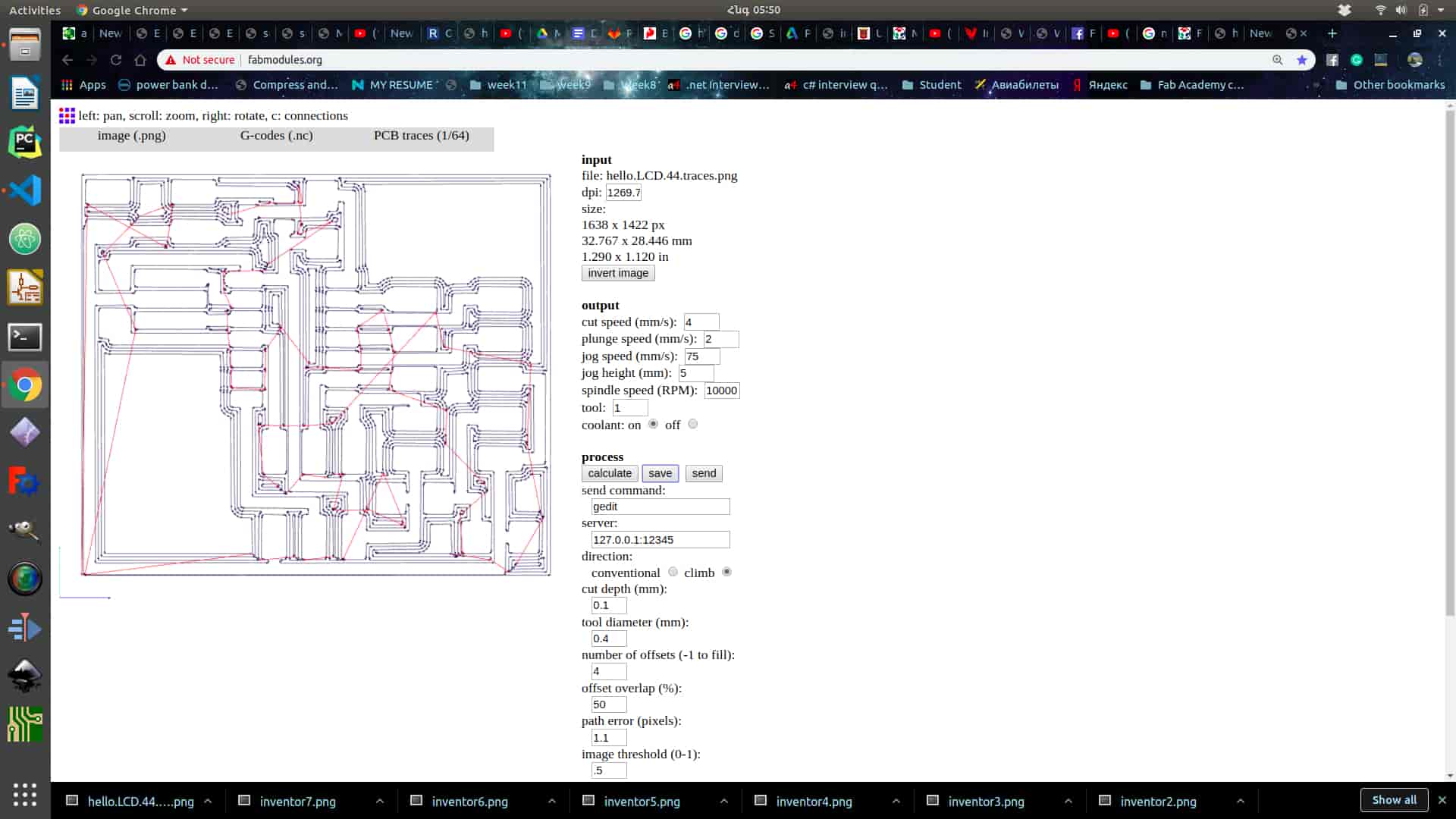
Import the image of your PCB In .png or another format .
Choose export format of the file . This is important because it must be readable for your machine . In my case I chose G-Code format which is working with different kinds of machines including SRM- 20 .There is also .rml file format which is exactly for SRM-20 and MDX-40 . But I used .nc or in another words G-code format in any case if your machine is different of mine .Choose 1/64 inch tool for traces .Adjust the parameters .In my case I haven't changed anything , I calculated it by default parameters . So after looking through parameters press calculate and wait . Press “Save” and save somewhere .Restart the page choose outline image and choose 1/32 inch tool for it (the file format is the same .nc ) . You can change the parameters , but I prefer to save it by default . And after saving the you got 2 files one for layout and one for cutout .
Board Milling
Clean up the area of machine , and board (make sure there is no oil on it).Make shure you got all tools
Stick Double-sided tape on the board tightly .Mount board inside the machine. mount board inside the machine .
Tight the tool in the spindle (By holding with the finger)
Before starting these steps you must read the manual .Open Vpanel for SRM-20 . Choose G54 in “Set Origin Point ” on the right side .Choose G54 in the left side .Go to Setup and choose “RML-1/NC Code ”. Choose the tool , at first 1/64 inches . (If you have not done it yet ).Tight the tool in the spindle.(If you have not done it yet ).Move the tool wherever you what to zero it .You can move it by using buttons in the middle +Y , -Y , +X , -X , +Z, -Z(be carefully with Z), you can adjust the speed of movement in “Cursor Step ” section . Press “X/Y” on the right side and click “Yes” , and press “Z” “Yes ” , it will change the origins by 0 .Make sure you have generated the files in Step 1 .Click “Cut” and press “Delete All”.Press add button and choose the g-code file . At first 1/64 inches file and press output .)Press “Red X ” , and the machine will start the milling proces .When it finish , press “View” button in the “Move” section .Change the tool to 1/32 inches . Zero the Z origin . Output the cut out file .And finaly will get the board .
Soldering
Clean up the space around .Make sure you have .
Make sure you have the electrical components . Remove unnecessary parts on the board with cutter . Clean up your PCB with water .Water the soldering iron sponge .Start Soldering
Solder by looking on schematics and layout .I added a jumper , after programming you can put it in one pin .
Individual assignment
LCD display
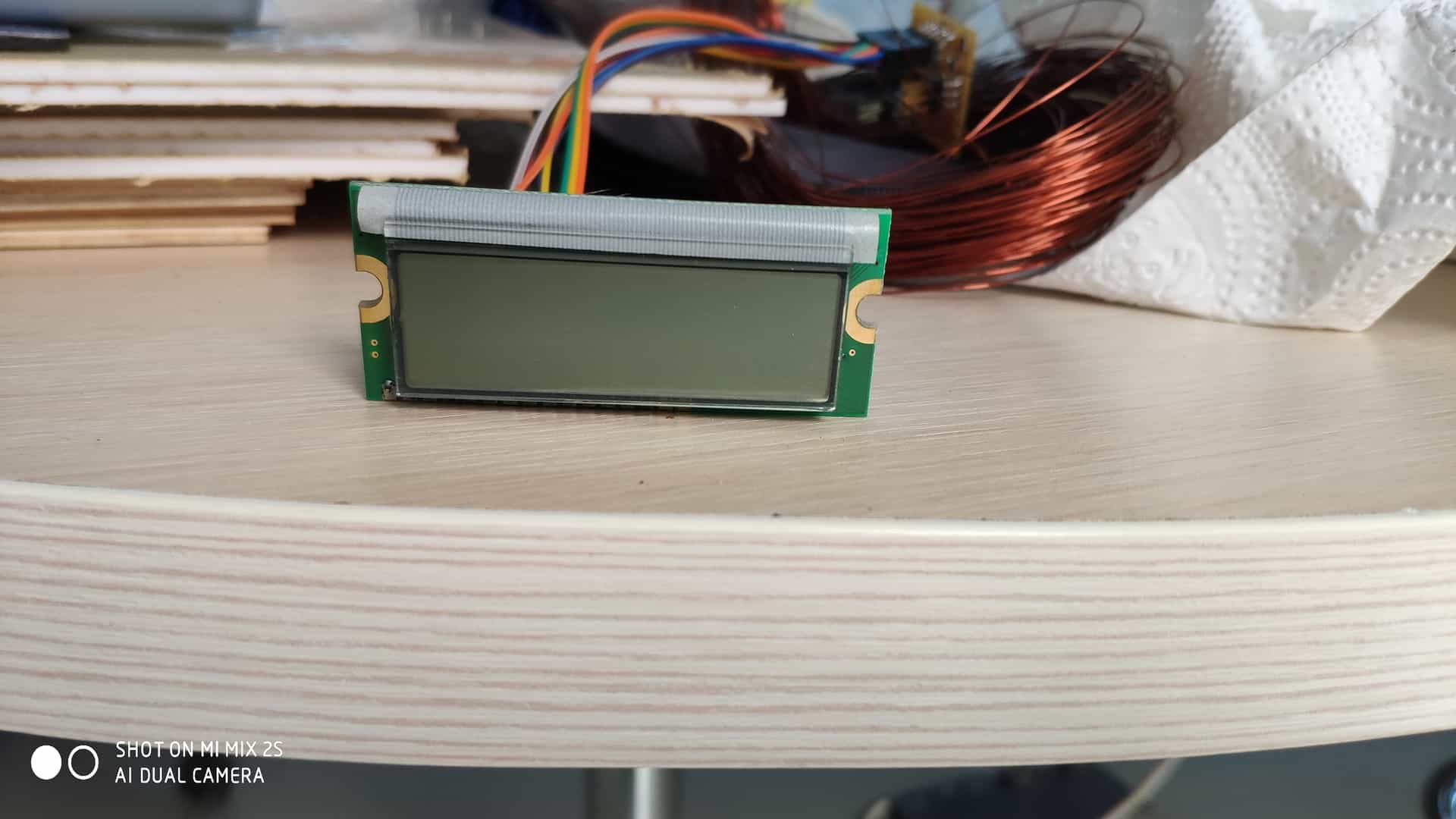
For this week I what to make board which runs LCD display , as a base I used Neils borads and code. The LCD display which used is lumex lcm-s01602dtr/m which 16 pins , but for running the display I used only 10 of them.
Features / Options
Applications / Uses
Board
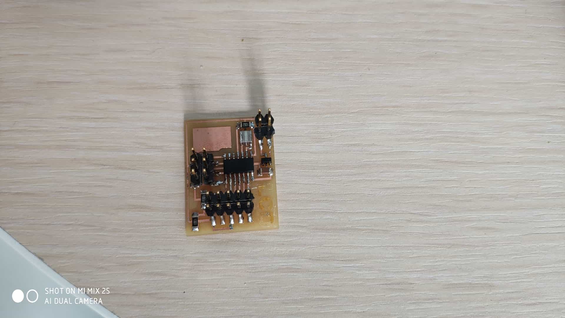
As a base for a board I used ATtiny44a .Also I used
Connections between microcotroller and LCD are
I mill the board using Rolland SRM-20, I generate g code using fab modules.After solder and connecting board pins to LCD I start programming part.
Code
As a base I use Neils code and make some chages on it
											//
											// hello.LCD.44.c
											//
											// LCD hello-world
											//
											// set lfuse to 0x5E for 20 MHz xtal
											//
											// Neil Gershenfeld
											// 11/14/10
											//
											// (c) Massachusetts Institute of Technology 2010
											// This work may be reproduced, modified, distributed,
											// performed, and displayed for any purpose. Copyright is
											// retained and must be preserved. The work is provided
											// as is; no warranty is provided, and users accept all
											// liability.
											//

											#include
											#include
											#include

											#define output(directions,pin) (directions |= pin) // set port direction for output
											#define set(port,pin) (port |= pin) // set port pin
											#define clear(port,pin) (port &= (~pin)) // clear port pin
											#define pin_test(pins,pin) (pins & pin) // test for port pin
											#define bit_test(byte,bit) (byte & (1 << bit)) // test for bit set

											#define LCD_port PORTA
											#define LCD_direction DDRA
											#define DB7 (1 << PA0)
											#define DB6 (1 << PA1)
											#define DB5 (1 << PA2)
											#define DB4 (1 << PA3)
											#define E (1 << PA4)
											#define RS (1 << PA5)

											#define long_delay() _delay_ms(1000) // delay before redraw
											#define lcd_delay() _delay_ms(10) // delay between commands
											#define strobe_delay() _delay_us(1) // delay for strobe

											//
											// lcd_putchar
											//    put character in lcdbyte
											//
											void lcd_putchar(char lcdbyte) {
											   //
											   // set RS for data
											   //
											   set(LCD_port, RS);
											   //
											   // output high nibble
											   //
											   if bit_test(lcdbyte, 7)
												  set(LCD_port, DB7);
											   else
												  clear(LCD_port, DB7);
											   if bit_test(lcdbyte, 6)
												  set(LCD_port, DB6);
											   else
												  clear(LCD_port, DB6);
											   if bit_test(lcdbyte, 5)
												  set(LCD_port, DB5);
											   else
												  clear(LCD_port, DB5);
											   if bit_test(lcdbyte, 4)
												  set(LCD_port, DB4);
											   else
												  clear(LCD_port, DB4);
											   //
											   // strobe E
											   //
											   strobe_delay();
											   set(LCD_port, E);
											   strobe_delay();
											   clear(LCD_port, E);
											   //
											   // wait
											   //
											   lcd_delay();
											   //
											   // output low nibble
											   //
											   if bit_test(lcdbyte, 3)
												  set(LCD_port, DB7);
											   else
												  clear(LCD_port, DB7);
											   if bit_test(lcdbyte, 2)
												  set(LCD_port, DB6);
											   else
												  clear(LCD_port, DB6);
											   if bit_test(lcdbyte, 1)
												  set(LCD_port, DB5);
											   else
												  clear(LCD_port, DB5);
											   if bit_test(lcdbyte, 0)
												  set(LCD_port, DB4);
											   else
												  clear(LCD_port, DB4);
											   //
											   // strobe E
											   //
											   strobe_delay();
											   set(LCD_port, E);
											   strobe_delay();
											   clear(LCD_port, E);
											   //
											   // wait and return
											   //
											   lcd_delay();
											   }
											//
											// lcd_putcmd
											//    put command in lcdbyte
											//
											void lcd_putcmd(char lcdbyte) {
											   //
											   // clear RS for command
											   //
											   clear(LCD_port, RS);
											   //
											   // output command bits
											   //
											   PORTA = lcdbyte;
											   //
											   // strobe E
											   //
											   strobe_delay();
											   set(LCD_port, E);
											   strobe_delay();
											   clear(LCD_port, E);
											   //
											   // wait and return
											   //
											   lcd_delay();
											   }
											//
											// lcd_putstring
											//    put a null-terminated string in flash
											//
											void lcd_putstring(PGM_P message) {
											   static uint8_t index;
											   static char chr;
											   index = 0;
											   while (1) {
												  chr = pgm_read_byte(&(message[index]));
												  if (chr == 0)
													 return;
												  lcd_putchar(chr);
												  ++index;
												  }
											   }
											//
											// lcd_init
											//    initialize the LCD
											//
											void lcd_init() {
											   //
											   // power-up delay
											   //
											   lcd_delay();
											   //
											   // initialization sequence
											   //
											   lcd_putcmd(DB5+DB4);
											   lcd_putcmd(DB5+DB4);
											   lcd_putcmd(DB5+DB4);
											   //
											   // 4-bit interface
											   //
											   lcd_putcmd(DB5);
											   //
											   // two lines, 5x7 font
											   //
											   lcd_putcmd(DB5);
											   lcd_putcmd(DB7);
											   //
											   // display on
											   //
											   lcd_putcmd(0);
											   lcd_putcmd(DB7+DB6+DB5);
											   //
											   // entry mode
											   //
											   lcd_putcmd(0);
											   lcd_putcmd(DB6+DB5);
											   }

											int main(void) {
											   //
											   // main
											   //
											   // set clock divider to /1
											   //
											   CLKPR = (1 << CLKPCE);
											   CLKPR = (0 << CLKPS3) | (0 << CLKPS2) | (0 << CLKPS1) | (0 << CLKPS0);
											   //
											   // initialize LCD pins
											   //
											   clear(LCD_port, DB7);
											   output(LCD_direction, DB7);
											   clear(LCD_port, DB6);
											   output(LCD_direction, DB6);
											   clear(LCD_port, DB5);
											   output(LCD_direction, DB5);
											   clear(LCD_port, DB4);
											   output(LCD_direction, DB4);
											   clear(LCD_port, E);
											   output(LCD_direction, E);
											   clear(LCD_port, RS);
											   output(LCD_direction, RS);
											   //
											   // initialize LCD
											   //
											   lcd_init();
											   //
											   // main loop
											   //
											   while (1) {
												  //
												  // go to zero position
												  //
												  lcd_putcmd(0);
												  lcd_putcmd(DB5);
												  //
												  // print first line from flash
												  //
												  static const char line1[] PROGMEM = "Hello to Ohad";
												  lcd_putstring((PGM_P) line1);
												  //
												  // move to second line
												  //
												  lcd_putcmd(DB7+DB6);
												  lcd_putcmd(0);
												  //
												  // print second line from flash
												  //
												  static const char line2[] PROGMEM = "Hello to fab academy";
												  lcd_putstring((PGM_P) line2);
												  //
												  // pause
												  //
												  long_delay();
												  //
												  // clear display
												  //
												  lcd_putcmd(0);
												  lcd_putcmd(DB4);
												  }
											   }
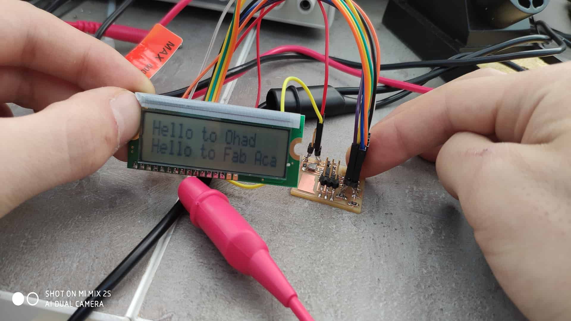
Conclusion
For this week my goal is make LCD work with the board. The only problem I had is wireing and one time i connect 5V and GND wrong and my board 5v regulator is burnd , I chage it and it works well.