
Computer-Aided Design
model (raster, vector, 2D, 3D, render, animate, simulate, …)
I did alot of raster graphics and vector graphics before using Photoshop and Illustrator. But this is a great opportunity for me to explore new tools that are free and open. Since I’m a school teacher free and open tools provide freedom to teach across the globe and especially in Armenia where GDP per capita is 3,936 $ (World Bank 2017) for comparison Israel’s GDP per capita is 40,270 $ (World Bank 2017) and world average GDP per capita is 10,721 $ (World Bank 2017).
Krita (raster graphics) Version 4.1.7
Krita is free and open
source painting
program very much like photoshop and you can do advanced raster editing after some learning. If
you are a
photoshop. I tried to open RGB colored and
CMYK colored
.psd files
which is Adobe Photoshop file extension and Krita easily opened it.
If you are a photoshop user, some tools and their shortcut keys might be little bit confusing
for example:
T that is Text tool in photoshop
brings up Move tool in Krita.
Gimp (raster graphics) Version 2.8.22
Gimp is another free and open
source
painting program very much like photoshop too and it’s more or less easier to navigate in my
estimation. I tried
to open RGB colored and
CMYK colored
.psd files
which is Adobe Photoshop file extension and unfortunately Gimp failed to open CMYK colored .psd
file. One nice
thing it has
special
plugin
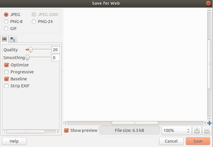
for saving for web which is one of my favorite parts.
After installing Gimp:
sudo apt install gimp
To get that plugin you just have to type:
sudo apt install gimp-save-for-web
after this you will have this wonderful option in your File menu.
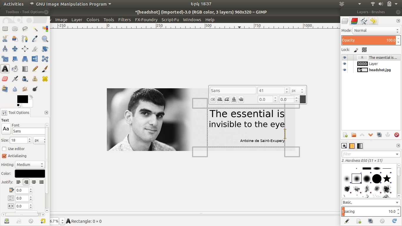
I tried to add one of my favorite quotes to my headshot, and I have to say that it’s rather easy to work with Gimp. Text tool is very intuitive and easy to use, but after I tried to scale it by dragging it’s corners it lost it’s editability and In my estimation it would be nice if editability stays unless you choose to change it manually.
Inkscape (vector graphics) Version 0.92.3
This is a free and open source vector graphics editor. The first thing I've noticed is it
supports .ai
and .eps files
these are Adobe Illustrator file formats and there are huge collections (freepik,
vecteezy) of shapes, logos and other
vector based graphics in this file format.
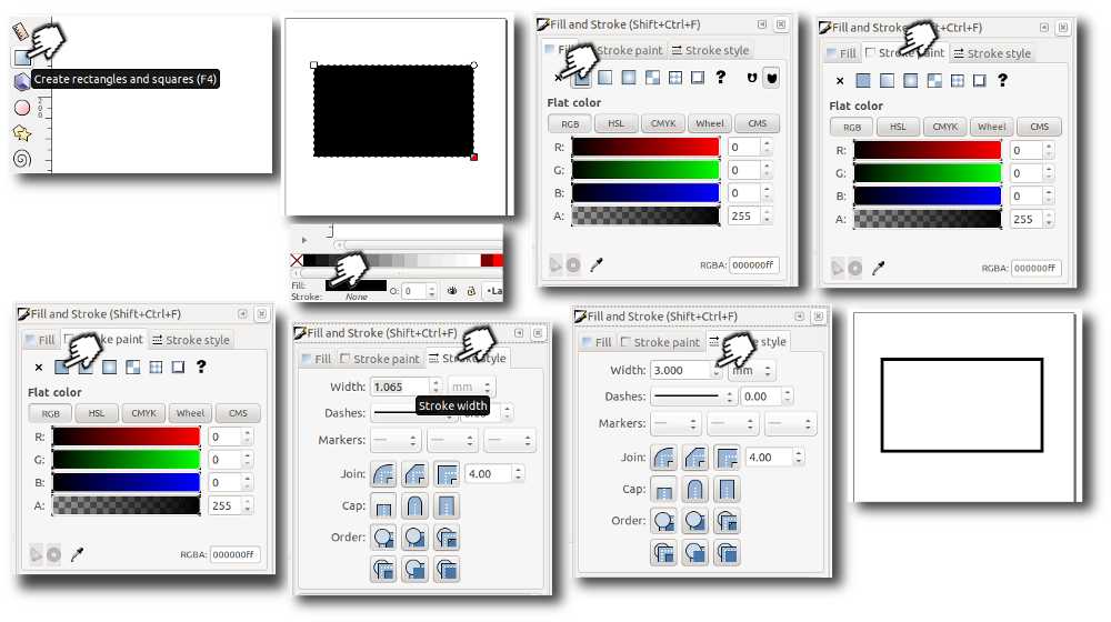
The next thing I did was to explore the main tools that I usually use. The first ones were
fill and stroke
settings that are essential.
The fill option is used to determine the properties of the area inside a geometrical objects
boundaries. For
example
you can have a colored rectangle or a rectangle with transparent area or no fill.
The next tool is stroke propertie tool that determines what options should the borders of a
geometrical
object have. For example the thickness, color or the style of the borders. Here is an simple
step by step image I
made with Gimp.
Since I'm not yet sure about my final project, I thought maybe drawing something interesting in
terms of
educating
myself and enriching our community might be a good idea.
Radio-frequency
identification (RFID) is very popular nowedays and you can find them almost in every
store on every product
they are embedded in many corporate ID cards and passports but the technology behind it is not
so obvious
particulary
for me. After surfing the net I found an interesting instructable on how to make RFID
Reader Detector using pieces of copper and cardboard. I thought maybe drawing the RFID
antenna with Inkscape
and describing further how to cut it on vinyl cutter might make it
easier for creative
communities and for me as part of it to explore RFID technology.
How to draw RFID antenna
I found a ready vector file
examples of RFID antennas you can use them too if you want to make a specific rfid
reder.
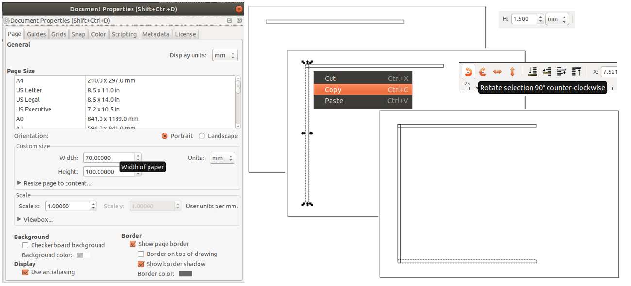
The one we'll be drawing is for 13.56 mhz reader. The first thing is to change the
document size to match our
needs. In our case we need 100x70mm (that's the cardboard size our antennna sticks to).
Next let's draw a rectangle and set it's with to 1.5mm manually from the upper right part of the
interface.
Then copy and paste the rectangle simply hitting Ctrl+C and Ctrl+V. Rotate the new
rectangle by 90
degrees and
place it according the image below. One nice feature of Inkscape is that this obects will snap
with their edges.
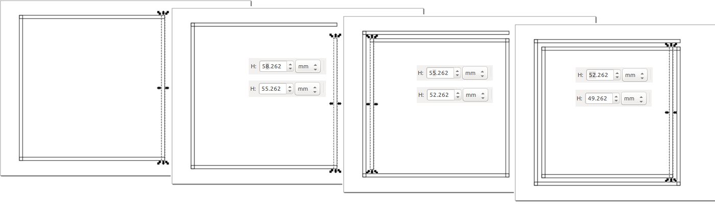
 Repeat those steps until you get a square. Now select the last rectangle and reduce it's height
by 3mm from the
upper right part of the interface. Then repeat copy and pasteing the new resized rectangle until
you get to
second smaller square inside the big one (see the picture below). Again change the last
rectangle's height by 3mm
and repeat copying and placing the rectangles.
Repeat those steps until you get a square. Now select the last rectangle and reduce it's height
by 3mm from the
upper right part of the interface. Then repeat copy and pasteing the new resized rectangle until
you get to
second smaller square inside the big one (see the picture below). Again change the last
rectangle's height by 3mm
and repeat copying and placing the rectangles.
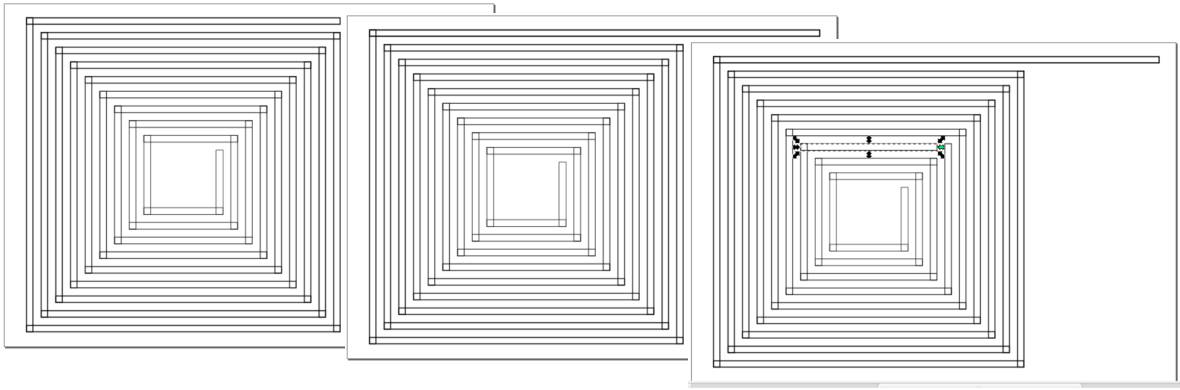
 Do this until you get desired amount of turns. We need 4 turns but in order to save material and
reduce the waste
I decided to have smaller antenna inside the big one. In order to separate this two antennas we
need to shorten
one of the rectangles.
Do this until you get desired amount of turns. We need 4 turns but in order to save material and
reduce the waste
I decided to have smaller antenna inside the big one. In order to separate this two antennas we
need to shorten
one of the rectangles.
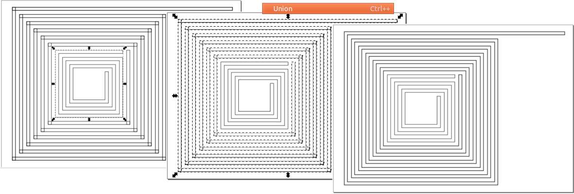
 Then select all rectangles that make the small antenna and join them by selecting
Path>>Union
or hit Ctrl++ do the same with big antenna you you will get two antennas like in the last
frame of the
image below.
Then select all rectangles that make the small antenna and join them by selecting
Path>>Union
or hit Ctrl++ do the same with big antenna you you will get two antennas like in the last
frame of the
image below.
 Here is the final file:
rfid antenna.svg
FreeCAD (3D)
FreeCAD is an opensource free Parametric Modeler software.
in order to install FreeCAD on linux open terminal and enter:
sudo add-apt-repository ppa:freecad-maintainers/freecad-stable
sudo apt-get update
sudo apt-get install freecad
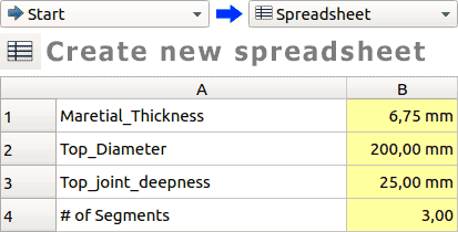
Here I will explain how to make parametric snap fit kit using FreeCAD. FreeCAD uses
spreadsheet to store parameters. In order to create one go to
Start select Spreadsheet and create a new spreadsheet.
Add parameters name them as you wish. In this case we need "Material Thickness" as a
parameter to
define joint width, "Top Diameter" for defining the main diameter, "Top
joint deepness" will define the joint height, "# of segments" will define how many
joints there will be on one piece.
Parameters
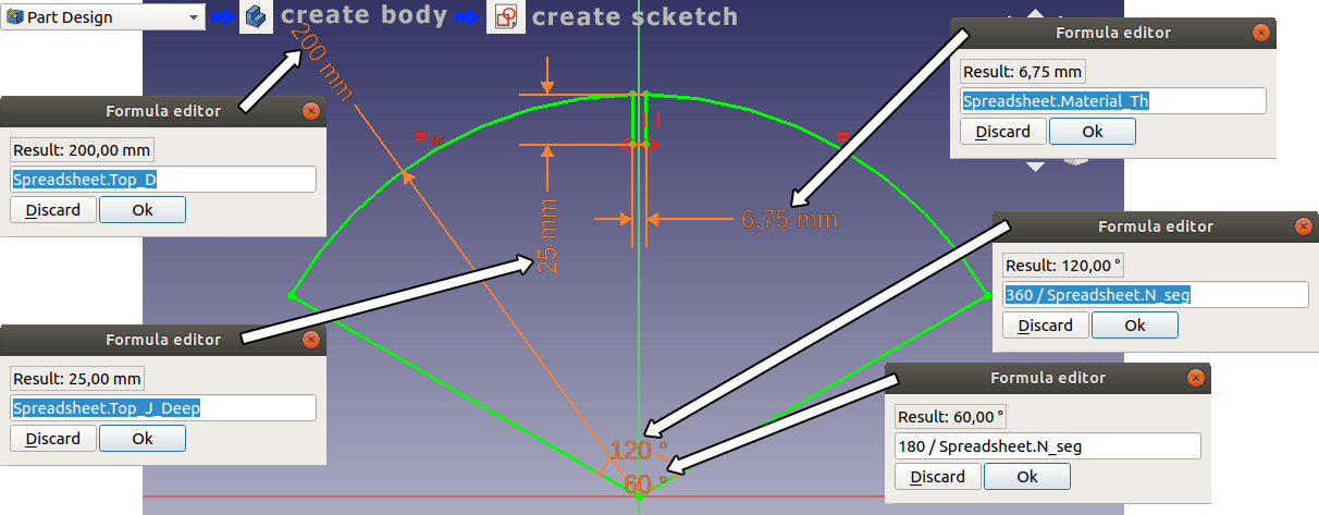
Now change Spreadsheet to Part Design workbench and click on the small blue shape that creates new body. Then click on the create scketch icon and draw using the tools of scketcher. Assign constraints using the constraints tools. Assigning sizes with parameters are also done with constraints.
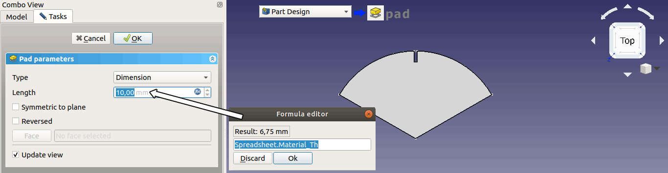
After finishing the sketching close the sketcher by hitting "OK" on the left side. Now select the sketch we just drawn and find the "Tab" button (image below) this will extrude the sketch. The lenght setting defines by how much the sketch will be extruded. I assigned a parametric value to this too.
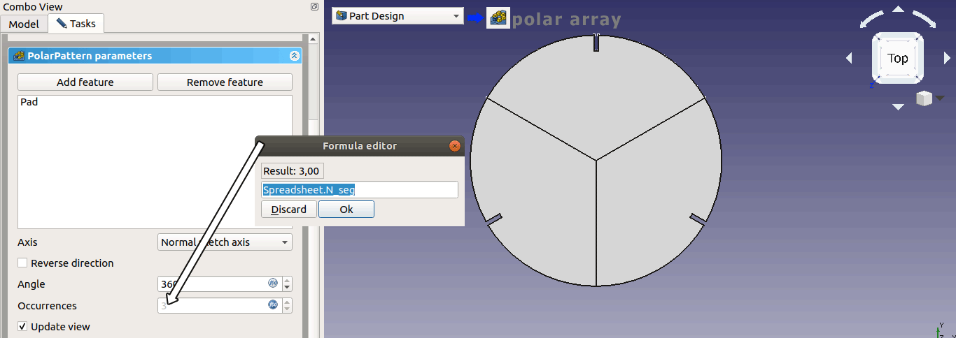
After finishing with the settings hit "OK" then we need to propagate this segment using "Polar array" tool.
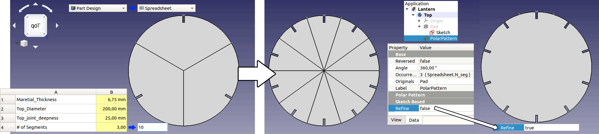
Now to see how parametric settings work go to spreadsheet and change number of segments from 3 to 10 and see what happens. To remove the segmentation find the "Refine" setting in polar array's options and change from "false" to "true".
Here is the FreeCAD file:
fit_kit.fcstd