
Molding and Casting Կաղապարներ և ձուլում
Introduction Ներածություն
For this week we had to:
review the safety data sheets for each of our molding and casting materials,
then make and compare test casts with each of them (group assignment)
design a 3D mold around the stock and tooling that we'll be using,
mill it, and use it to cast parts (individual assignment)
Creating the Positive Mold Model
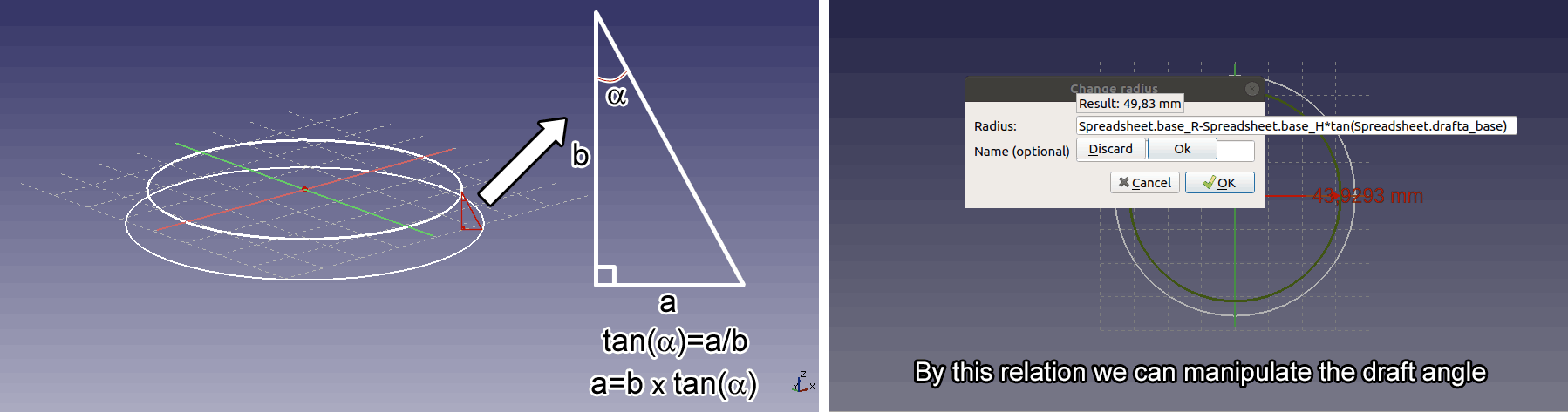
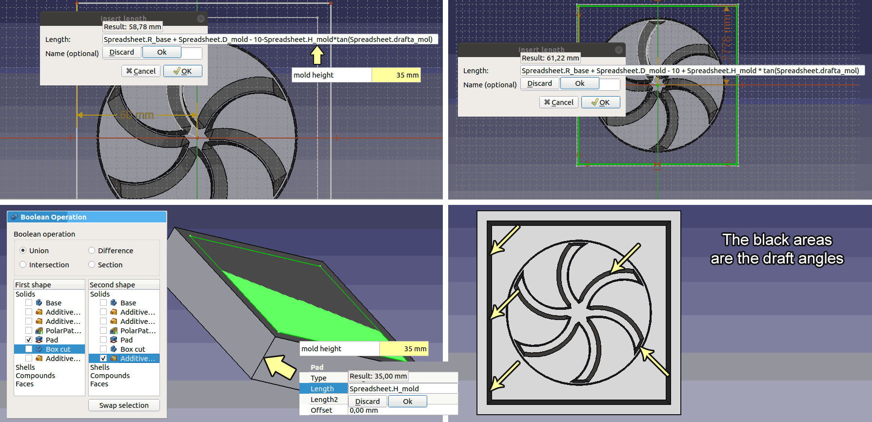
While designing a mold it's nessesary to consider the draft angles of each wall, we need this angles in order to take out parts from the mold easily. That's why I decided to have a parametric model where I can change the draft angles. This is the 4th week that I strugle to conquer Freecad modeler and this is the week I finally got results I'm satisfied. I thought that designing a model with parametric draft angles would be cool. So I started to wonder how to do it and remebered from school class the Trigonometric functions. In this case the ratio between opposite side and adjesent side of the triangle for a given angle is constant and it's called Tangent. By multiplying the adjesent side in our case the height of the model by tangent of an angle we can have the opposite side in our case the difference of the radiuses of the model. (see image below) Since Freecad uses spreadsheet to take parameters it easily calculates this relationships.
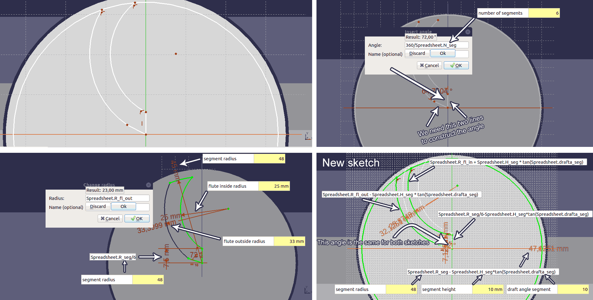
So I had a base for my model with a parametric draft angle. I decided to model a little propeller that could work as a mixer. Next I started to model the sketch for the propeller again assigning parameters to each part of the sketch in order to get fully constrained sketch with 0 degrees of freedom. The names of parameters are starting with segment because it's going to become an array.
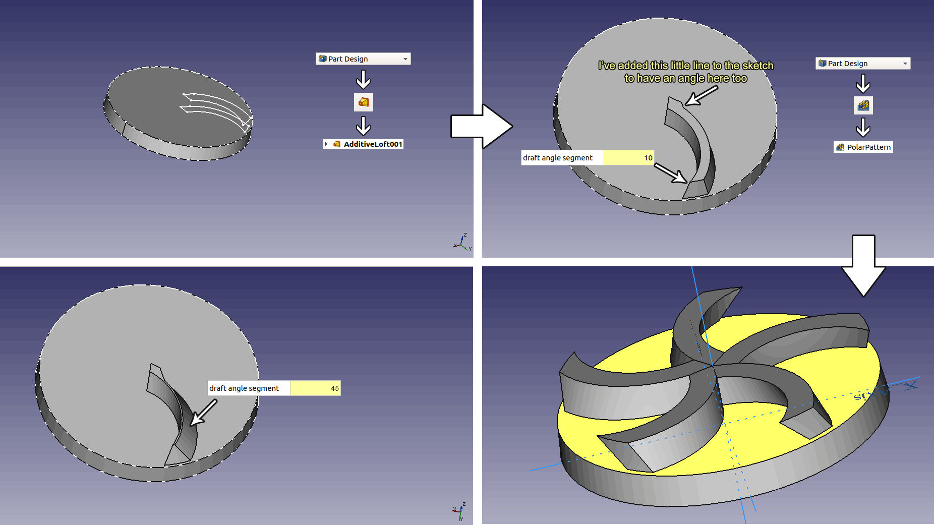
Then I've selected Additive loft tool by going to Part Design>>Additive Loft (see image below) and created the segment. Then I've selected the generated Additive Loft and selected the Polar pattern tool by going to Part Design>>Polar pattern (see image below)
Milling the Wax on the SRM20
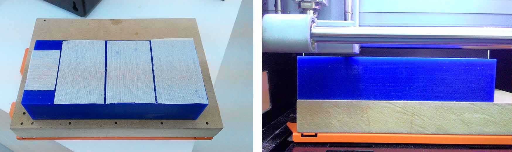
After completing the modelling I've exported my model as .stl file made sure it's not in capital letters. I took the smallest standard brick of machinable wax that's 76x178mm and attached to SRM20 milling machines table with two sided tape. As you can see from the photo the stock was too close to the spindle head so I was limited what my tool lenght should be.
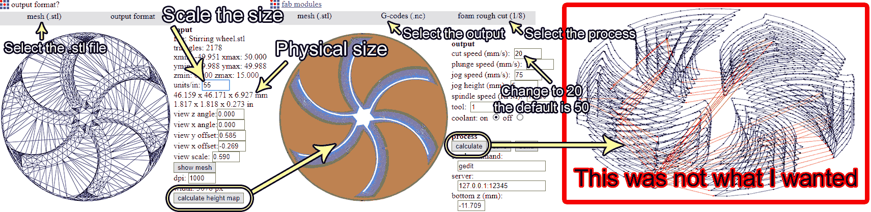
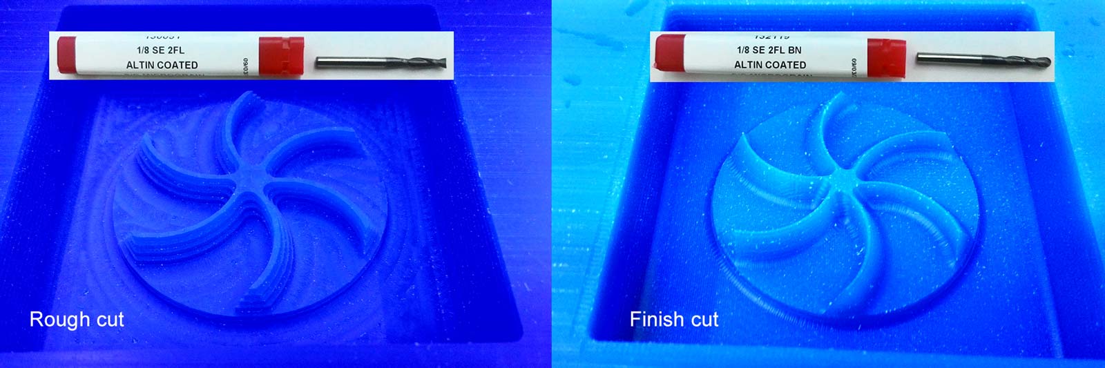
Next I took the 1/8in endmills. Flat head for rough cutting and ball head for finish cutting.And made sure the fit with the stock and spindle. Then I went to Fabmodules.org to generate the toolpaths. I've selected G-code(NC code) as my output although you can choose Roland native .rml format. Then choose the process "foam rough 1/8" If you are doing this with G-code you have to change the cutting speed from default value 50mm/s to 20mm/s (see image below) that's the recommended speed for both rough and finish cuts of machinable wax. Unfortunately this was not the right toolpath beacause it's just milling the part without a boundary box. We need that volume around the part, this wolume is what our mold should look like.
So I had to go back and add a parametric boundary box to my model. I made a new body named it "Box" and created two sketches on XY plane, draw a rectangle you can see in the image below, then I've created new parameters in the spreadsheet and assigned the parameters to the sketches. Next I made a new body called "Box Cut" this one also considers draft angle. Finaly I applied a boolean operation and substracted "Box cut" from "Box"
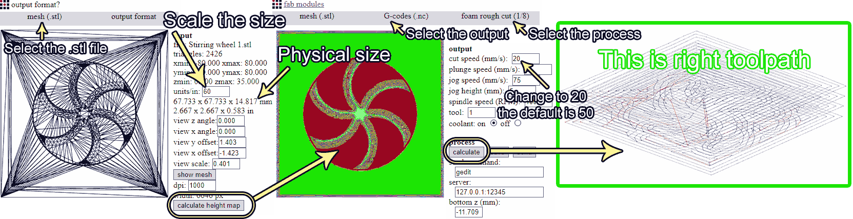
After I went to Fabmodules.org and now the toolpath was right it had a boundary box around the part. Select the output, I prefer G-code(NC code) although you can choose Roland native .rml format. Then choose the process "foam rough 1/8" If you are doing this with G-code you have to change the cutting speed from default value 50mm/s to 20mm/s (see image below) that's the recommended speed for both rough and finish cuts of machinable wax hit calculate and waite (it might take some time). Save it and mill it.
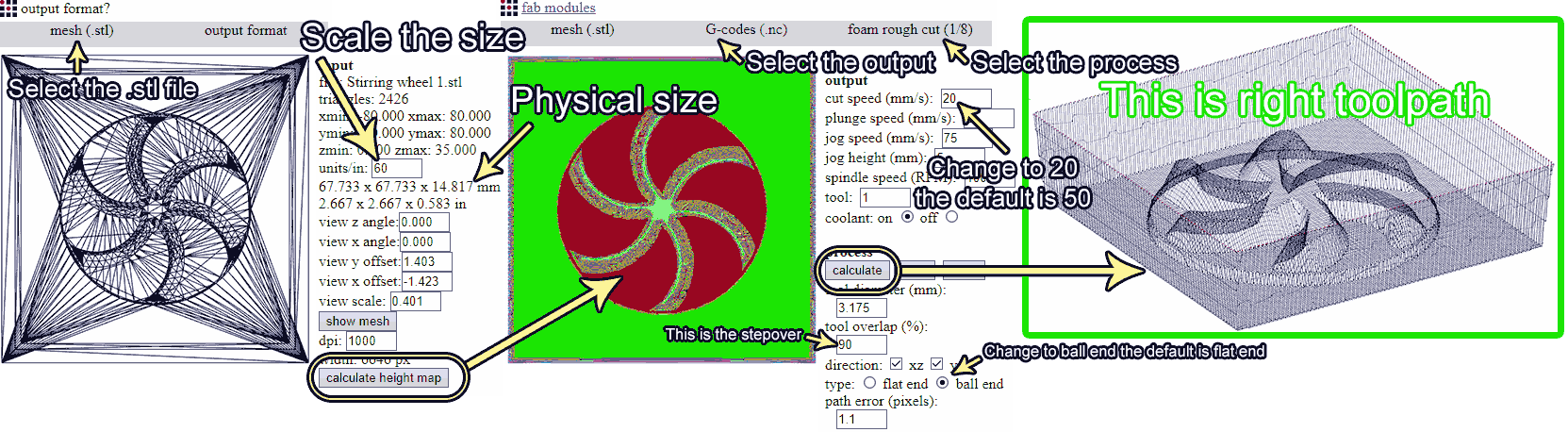
After rough cut is done do the same thing but instead of "rough cut 1/8" select "finish cut 1/8" as process again change the cutting speed to 20mm/s. Also scroll down and change type to "ball end" the default is "flat end" and if your bit on the machine is ball head and this setting stay flat end your tool will not touch the material at all. I learned this by doing this mistake.
Here are the results. In my estimation the space between the walls and the model was too much so I milled another one with less space and this way my model turned out a little bit bigger.
Making the Mold from the Wax
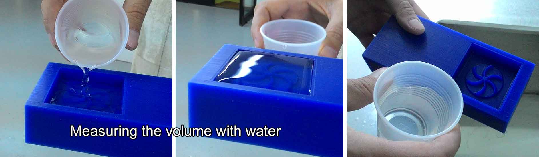
I wanted to use OOMOO 25 two component mold compound but unfortunately one of the components (part A) was hardened while it should have been liquid I tried to stirr it but it was sticky and hard like a chewing gum. I used PMC 121/30 urethane mold compound. I measured the volume needed for the mold by filling water into the machined wax and then filling back into an empty cup.
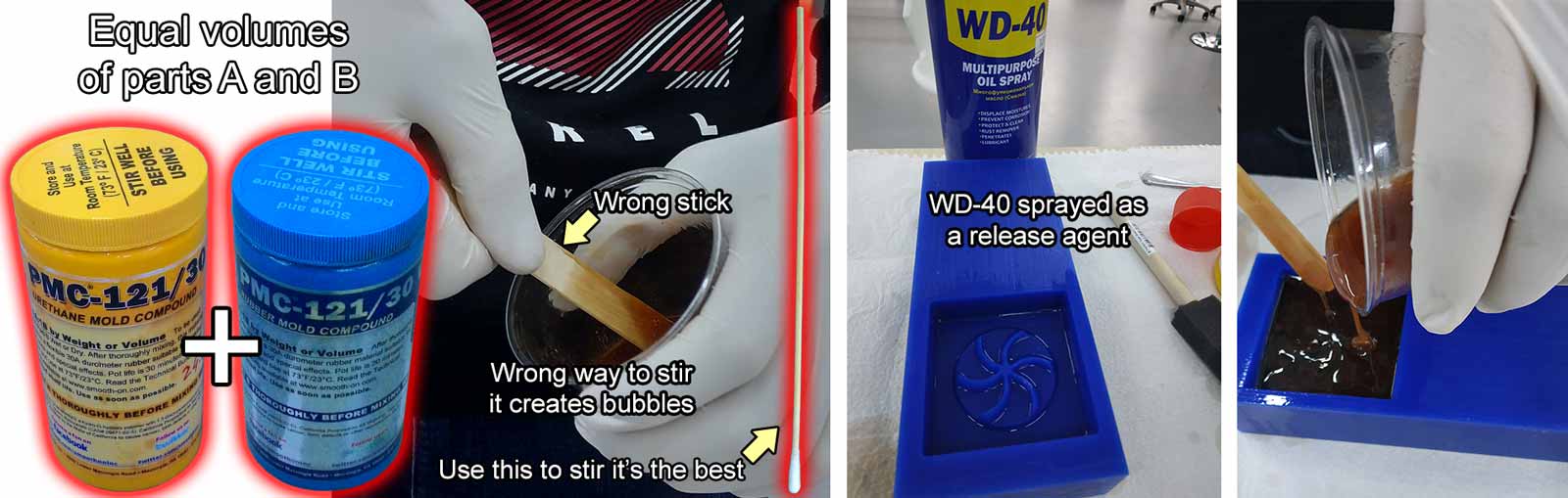
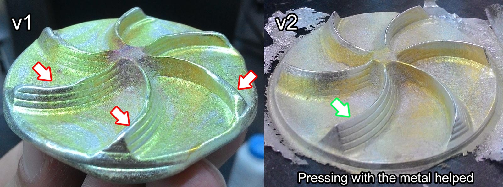
Next I took each parts of PMC 121/30, shaked them well. Then poured each part with equal volumes into cups and mixed them to be about same volume as the cup of water we got from the previous step. Then I began to stir it with the medical tongue depressor (the doctor's stick) which was not the best thing to do. After that I found an old video where Neil shows to some guys how to stir pour and make molds with PMC 121/30, here's that video. He suggests to stir the compounds with 150mm (6in) cotton tipped applicators (see image below) (which I did for the next version), because they are so thin and round they don't create bubbles while stirring.
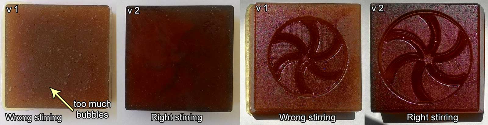
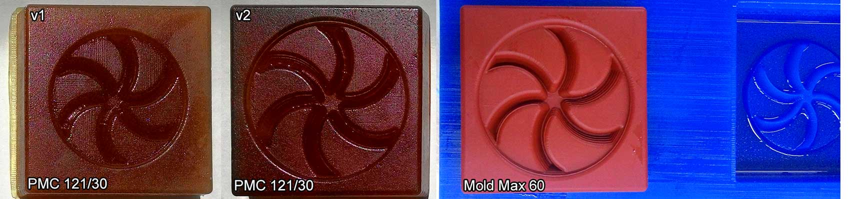
I made another one this time stirring with cotton tipped applicators. Here are the resulting molds. As one can see the v1 has lots of bubbles while
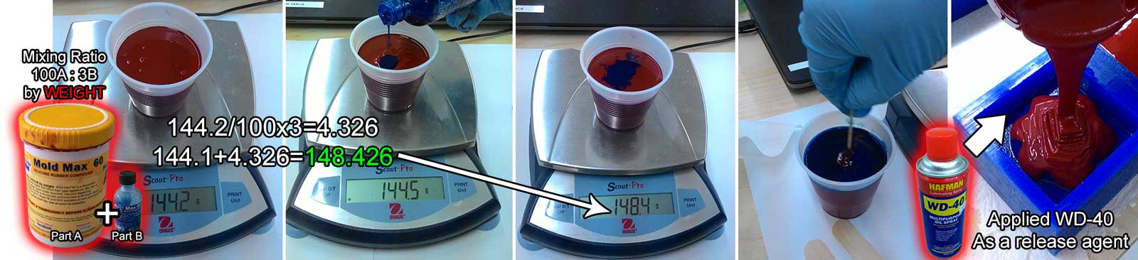
I also wanted to try metal casting so I had to make another mold that could resist high temperatures. This tutorial was very helpful. I used Mold Max 60 it's a high heat resistant (up to 560°F/294°C) silicone rubber compound. Pot life is 40 minutes and cure time is 24 hours. You need to have 100A:3B ratio of part A and part B. I poured part A into a cup measured it's weight then calculated the weight for the part B and added the weights of each component. Then I poured part B into the cup until it reached the added number. (see image below)
After 24 hours I took it off with the help of a screwdriver tip. Here are all the molds I made the forst two are made with PMC 121/30 urethane mold compound and the last one with Mold Max 60 high temperature resistant mold.
Casting Final Object
I used two materials fo casting:
Smooth-Cast 305 casting
resin for plastic
Babbitt(alloy) for metal casting
Plastic (Smooth-Cast 305)
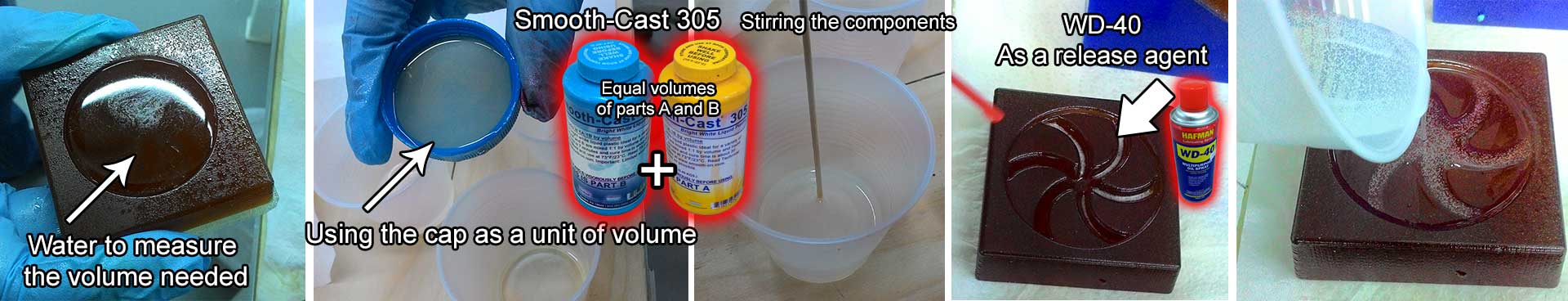
Smooth-Cast 305 is a ultra-low viscosity casting resin. It cures in 30 - 40 min, low mass or thin-walled castings will take longer to cure. I measured the volume of the part by pouring water into the mold then filling that water into a cup. Make sure to clean and dry up the mold after that step. I sprayed WD-49 to the mold surface as a release agent and spread it with a brush. Then I thoroughly shaken up the two components of Smooth-Cast 305 and since the bottles are exactly the same size I used the caps of the bottles as a volume unit. I pured two caps of each component into a cup that was about the same level as the water in the cup I used to measure the volume needed. Then mixed the compound and poured into the mold. It is recommended to pour the the resin in a single spot at the lowest point of the containment field and let the mixture seek its level.
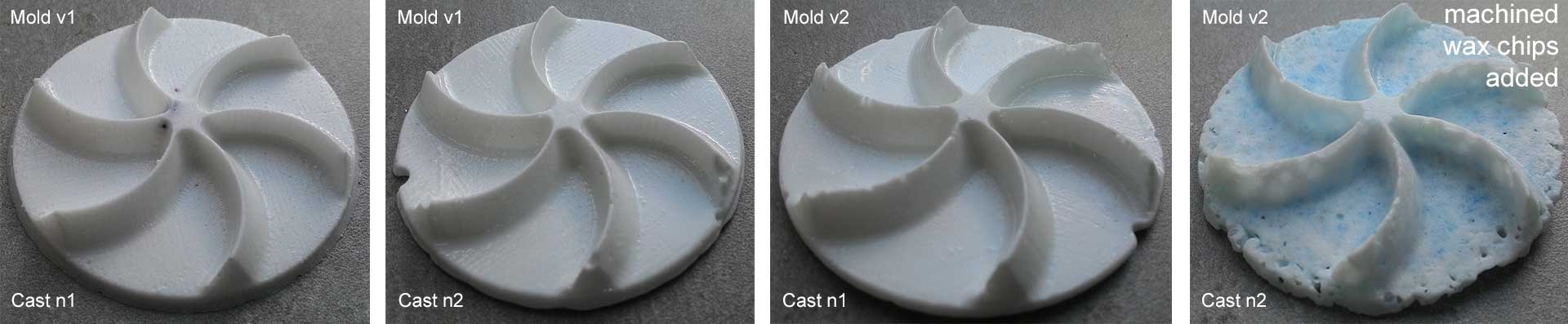
The first cast model turned out the best because I stirred the resin with the medical tongue depressor. The other ones were stirred with the cotton tipped applicators. One of our Fabacademy students Mariam had a great idea to add the machined wax chips to the compound and have an interesting pattern.
Metal (Babbitt alloy)
Always use special heat resistant gloves while handling melted alloys! Babbitt(alloy) RotoNickel Babbitt is a durable Babbitt alloy consisting of approximately 89% Tin, 3.45% Copper, 7.5% Antimony, and .15% of Monel which contains Nickel. The melting temperature of this alloy is 241 C (466 F).more on this. I've cut the ingot and put the small piece in the Vulcan A 550 oven in a special heat resistant cup. At first I adjusted the temperature of the oven to be 250 C but after waiting about half anhour I realised I need to increase it so I increased the temperature to 315 C like this tutorial suggests. I was opening the lid and checking periodically to make sure it's melting. Then I've applied talk powder as a release agent. Then poured carefully the melted alloy into the mold.
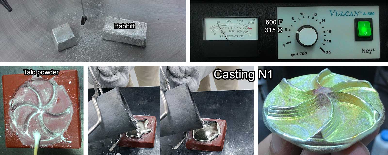
As you can see the edges are not filled and the bottom part is very thick because of the surface tension. I melted this model and found an iron rod to press the liquid babbit from the backside of the mold. I placed the iron rod in the oven to incease the time I can make adjustments by it, because if it would be cold the liquid babbitt will harden as soon as it touches the rod.
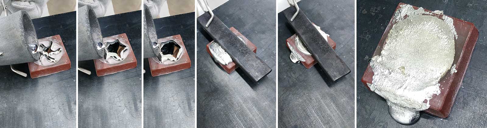
Here are the results. Pressing drastically improved the casting.
Conclusion
Stir PMC 121/30 and Mold Max 60 with cotton tipped applicators.
Stir Smooth-Cast-305 resin with medical tongue depressors.
Press the babbitt in the mold while it's liquid with a metal part to get perfectly shaped parts.
Here are the CAD files for my mold.
Freecad file
.stl file