-
Assignment
3D Scanning & Printing3D Scanning and Printing
I started this week assignment by using 3D softwares to build a 3D object trying to make somthing that can't be done using subtractive machines such as milling machine
I created a new document using Onshape to design something that cann't be fabricatd as one pice using subtractive 3-axis machines. I started the project by hide all the planes and keep the top to create the sketch. The top plane was selected to do the first sketch, I added ellipse and edited the dimensions, I used offset tool to make another layer of ellipse. I'm planning to design simple vase
I extrude the design by 3 inch and added draft 5 deg
I created new plane on the top of the extrude to make new sketch. I added the same ellipse but I rotate it 120 deg
I extrude the sketch that I just created by 5 inch
There is a space that should be covered between the two designs, I extrude it by 0.5 inch
The bottom should be covered as well, I did the same by 5 inch
I used fllet tool to make the design edges smoother and curved. it was circular with 0.5 inch radius
I used fllet tool as well to make the design edges smoother and curved from the bottom. it was circular with 1 inch radius
I created new sketch on the bottom of the design and added a circle to create a base
I added another plane with respect of the top plane and distance 1.5 inch
I added new circle on the new plane that I just created
I selected the two circles and clicked on loft icon to create the base. I chose normal to profile to make the design smoother
The final result that I got as shown below
I created a new document in Onshape to design something that can be used in my final project, suitable for the robot requirements. I started the project by hide all the planes and keep the top to create the sketch. The top plane was selected to do the first sketch, I added the rectangular and edited the dimensions to be 108mm * 150mm and then and as I was going to extrude the edges I used the offset tool to create a copy of the outer edge with 3mm space to be connected and being closed loop to be able to extrude. I used digital caliper to measure the motors dimensions to make the suitable places. I did all the sketches in one side, to use mirror tool after that to mirror everything to take the same positions as I selected the mirror lines reference to be in the middle of the rectangular. The other holes are created to fix some other components like electronics stuff
By selecting the main rectangulare to be 8mm extruded
I did the same thing for the outer closed loop that was created by the offset with 3mm space, and to be 23mm extruded
As the robot will move, the motors should have high level of stabilization and fix with balance to be able to move. So, I created new sketches at the side plane to do the space to put screws in order to fix the motor as the motors that I have here have two holes that can be used for fixing by screws and nuts
By doing the same thing but different sketch plane to be on the other side, then, I selected them and clicked on extrude, but this time I selected remove, to make the subtract on the material itself
It was removed by 3mm because the material thickness was set 3mm. I was planning to use IR sensors to do the tracking, So, I considered this and made new sketch on the front chassis plane to do the holders and add the front balance for the robot instead of adding new wheels or motors. I used digital caliper to measure the sensor with holes where I can fix it, the sensors should be close to the ground to detect the path that should take
Clicked on the sketch fillet icon to make the edges smooth to reduce the friction especially while robot moving. I extruded the sketches by 4mm
On the other side, I was planning to fix 16*2 LCD screen with push buttons to be as control panel where the user can interface and interact simply with the robot to be user friendly. I created a new sketch in the plane and did 2 holes and used mirror to copy them one more time
And by removing the material at the holes, from extrude tool by 3mm
Now, the design is ready. This design is difficult to make using subtractive technologies, as it has holes and details that a normal 3 axis machine cannot do them
I want to print the design out using Prusa 3D printer. There is an amazing program called PrusaSlicer that allows the user to make the settings before printing based on the material and the design. First I exported the design as STL from Onshape, then I opened PrusaSlicer program and imported the STL that was exported from Onshape
Now, the program shows the very important settings in the main page (tab). This tab called Plater. The first thing is the print settings I made it 0.2, this means the layer height. Then, the type of filament that I’m going to use, I selected Generic PET, because I’m going to use PETG filament. After that, what is the printer that I’m going to use, I have here Prusa i3 MK3. Finally, if you need support (if the design has suspending parts), in my case I will not use support at all because the design is stable, and I set the infill to be 20% (the more infill, the more filament and will be strong). The main page also allows more options such as rotate the design on the printer plate or move it or place it in a different position or arrange the parts if I have number of parts to be printed at once
If I need to edit more settings, I have to check the other tabs, I started with next tab which is print settings. This tab has many additional settings belong to the print itself such as layer height, infill, and some others. I did change the perimeters, as the print needs to be strong enough, it’s the number of perimeters generates for each layer
In the same tab, I checked the speed icon as it shows the printer speed in different layers
I moved to the next tab, which is filament settings, this tab shows very important settings such as filament diameter, the nozzle temperature, and bed temperature. Theses parameters depend on the filament that I’m going to use which is PETG. As I selected generic PET, the program has default settings for that but it can be adjusted, I had to read the PETG filament sheet to make sure the temperatures are fine
It’s very important to note the cooling system, the fans’ speed. They can affect the print
I checked the last tab which is printer settings. This tab allows me to check the parameters belong to the printer itself. The important note here is the diameter of the nozzle. I have 0.4mm nozzle. Also, the printer limits and the Gcode if it will be customized
Finally, I moved back to the first tab which is plater to finalize the slice and get the Gcode. I clicked on slice now, it took a few seconds to do it and then the G-Code is ready to be exported shifted to my SD card. It’s good to note that the program gives me the filament needed to use filament spool enough, also the cost, in addition to the time needed
It’s good also to check the layers by sliding the road, the most important layer is the first layer, to be stable and on the bed directly
Now, I exported the G-code, and saved in on the SD card. I just insert the SD card and select the file name. It took a few minutes to heat up the nozzle and bed, then it started printing. I keep watching the printer especially for first layers
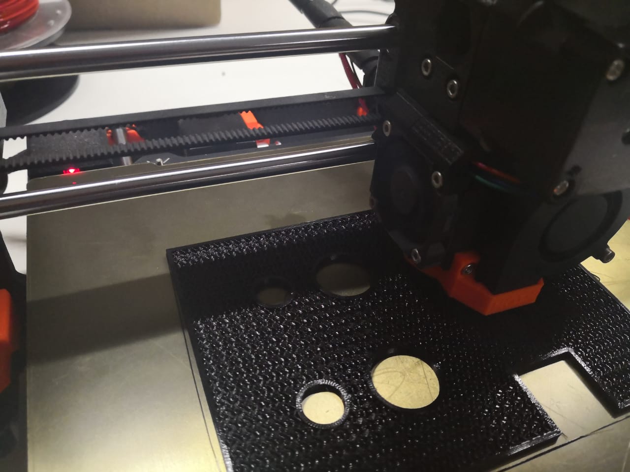
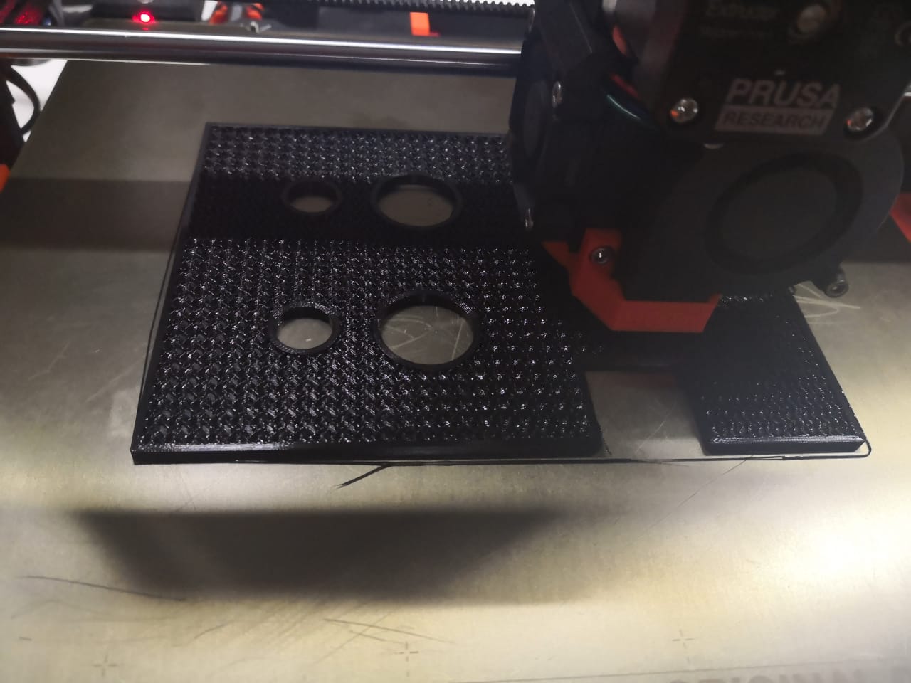
The print is going smoothly
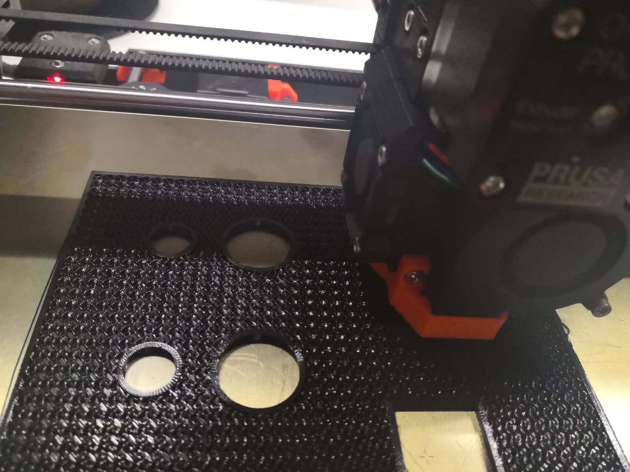
Now, the print is ready, I removed the bed and took the print easily
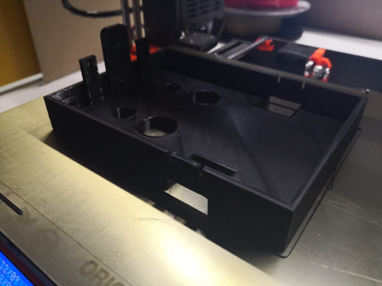
I changed some holes diameter and added new holes, I did the same steps to start printing, I exported the model as stl and drop it in Prusaslicer, and checked the settings as I was going to use PETG. I did slice and export as G-code to start printing. The printing process went smoothly without any problem
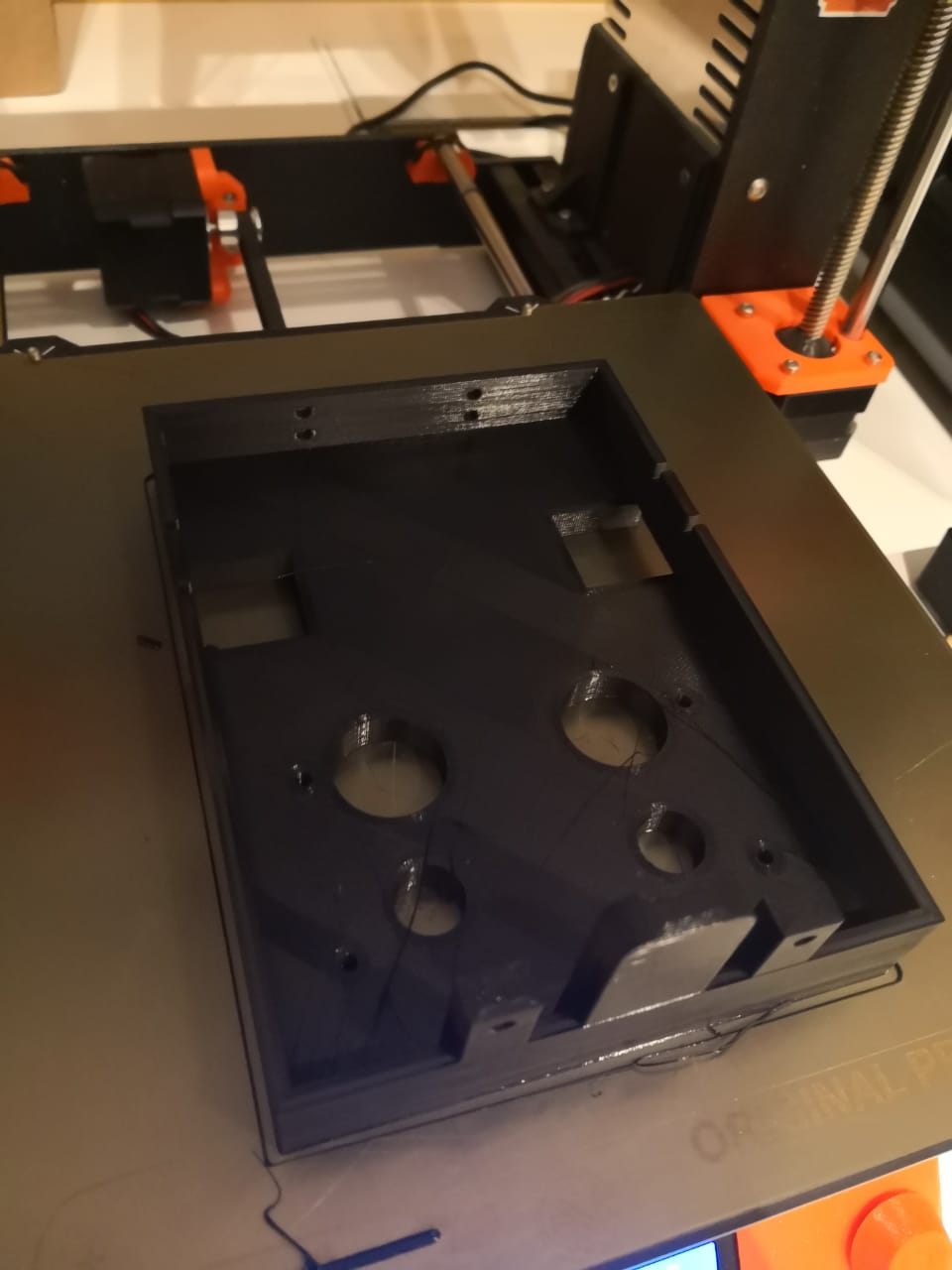
I started designing board holder where I can fix the electronics board and drivers. I tried to utilize the space on the top of the chassis to cover as much components and boards as I can. The space between the motors is narrow but the other side wider. I did a simple sketch based on the measurement that I took by using digital caliper
By copying the design and rotate the sketch that I have done, this looks really good (I shifted the design because of the picking mechanism that I’m planning to design and will be fixed on the two small holes) I did the holes to fix the boards and the model with chassis
Using the extruding tool to extrude the inner loop by 2mm and outer loop by 15mm to get the design ready
Now, exporting the design as stl and using Prusaslicer to prepare the printable form which is Gcode. The printing process went smoothly and done
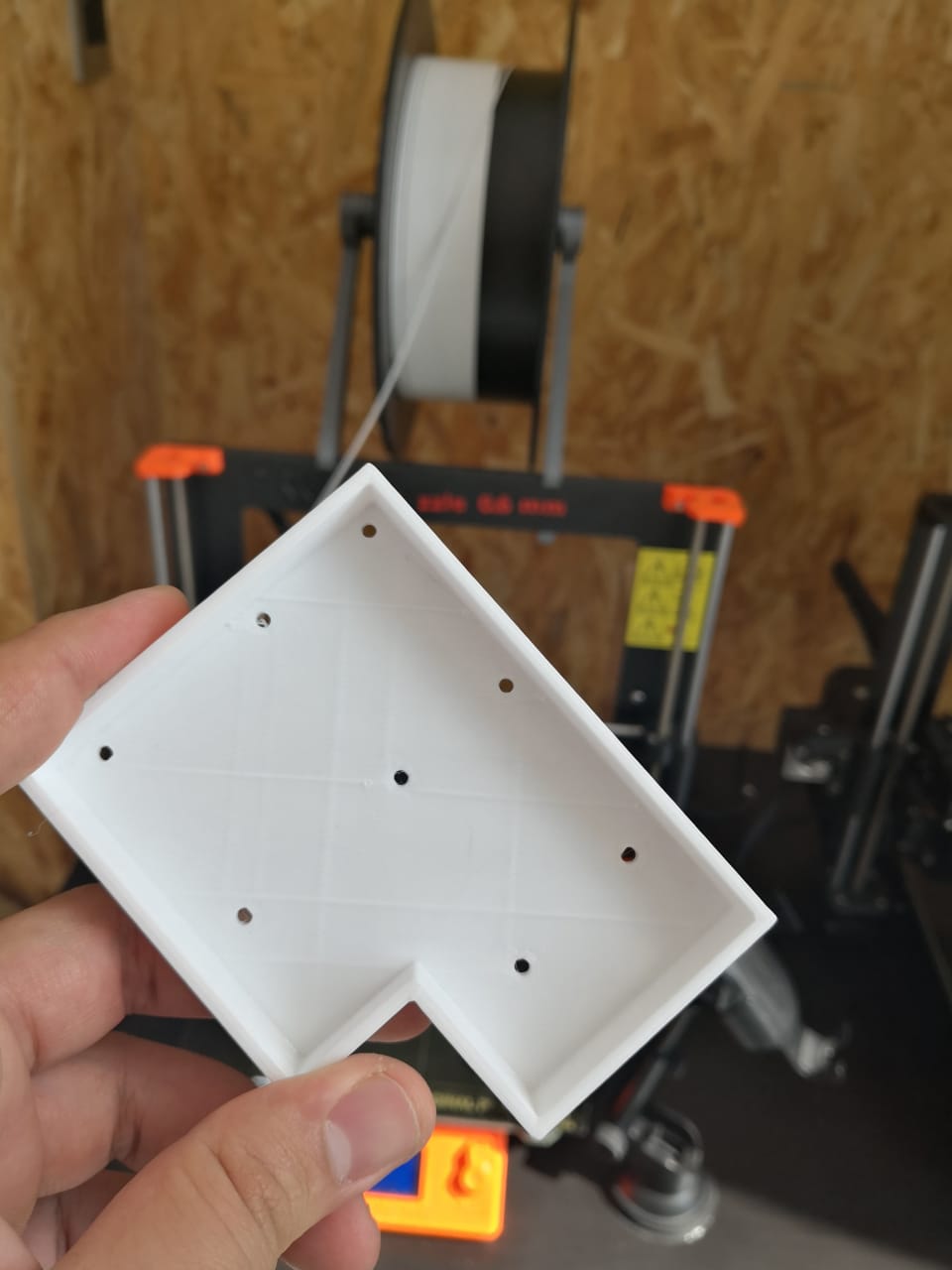
I recorded video as time-lapse to record and document the process
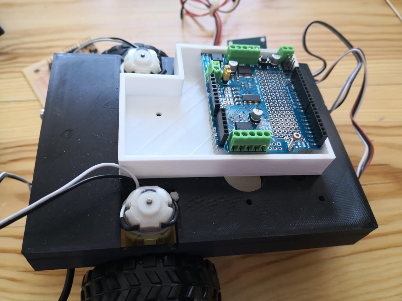
I fixed it on the top of the robot chassis by using 2.5mm screws with nuts and fixed the motor shield as well
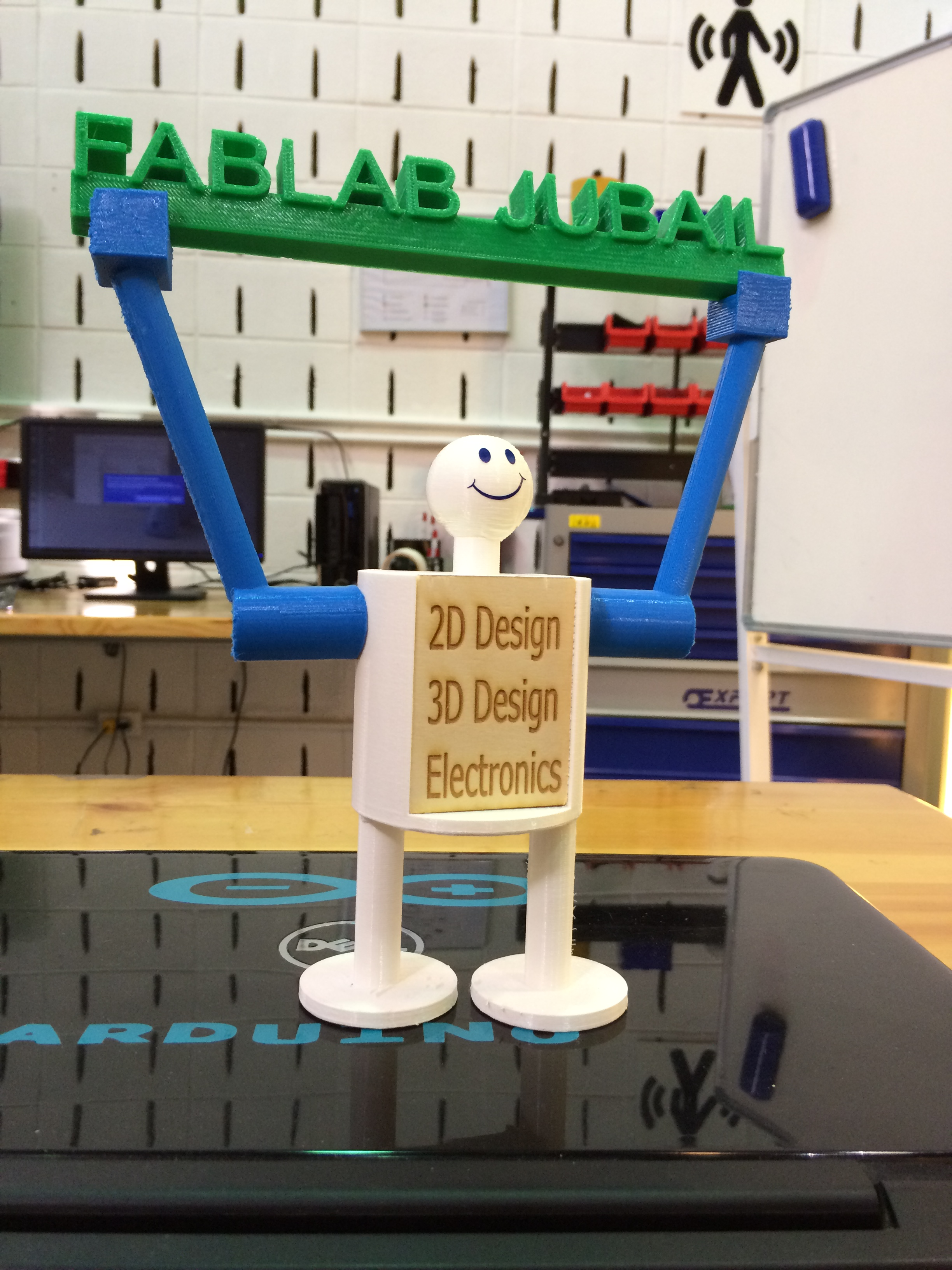
One of my very first project in 3D field a couple of years ago, I built a humaniod robot (head, body, hands, and legs) check the photo below illustrates the object with different views
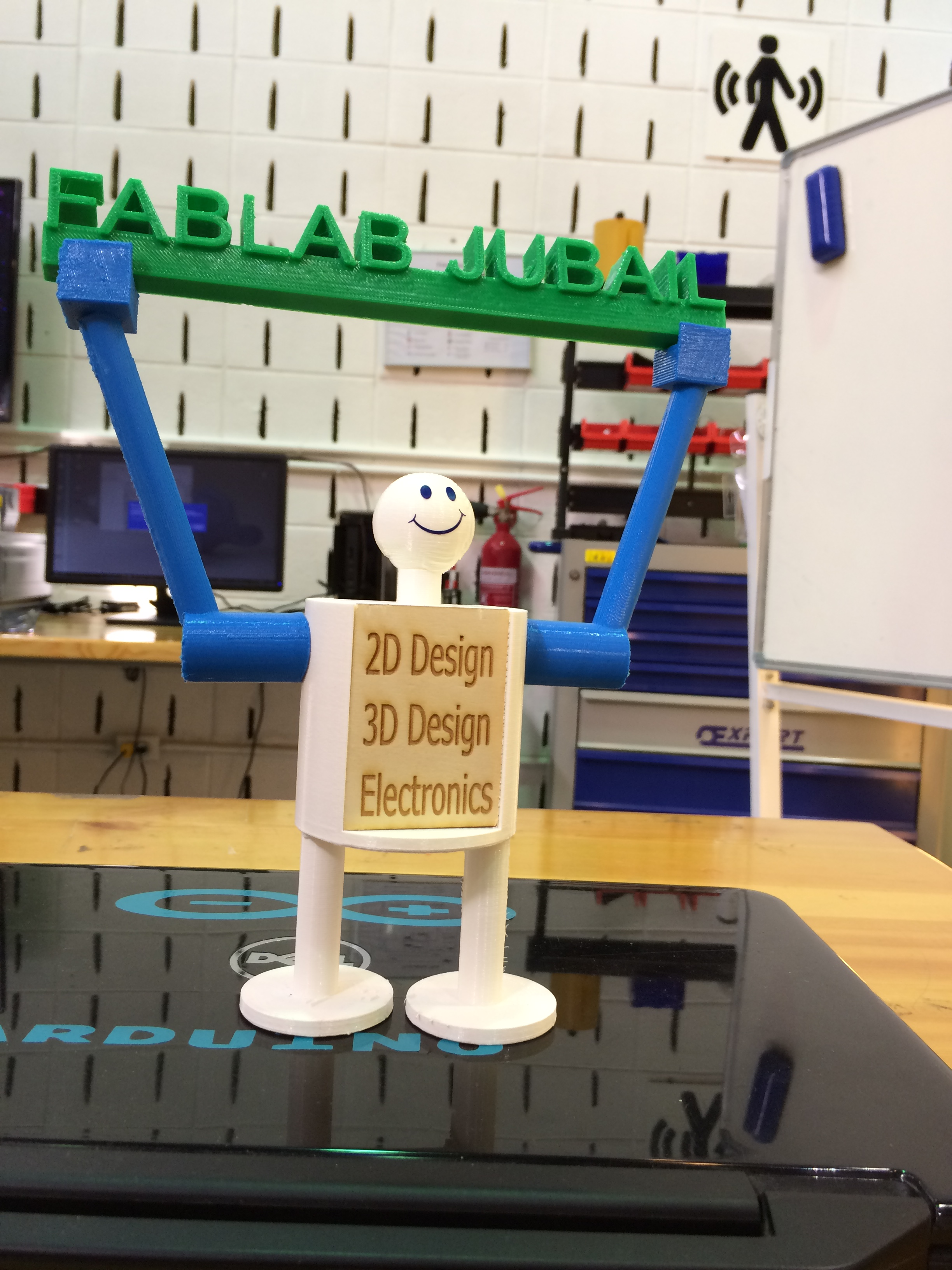
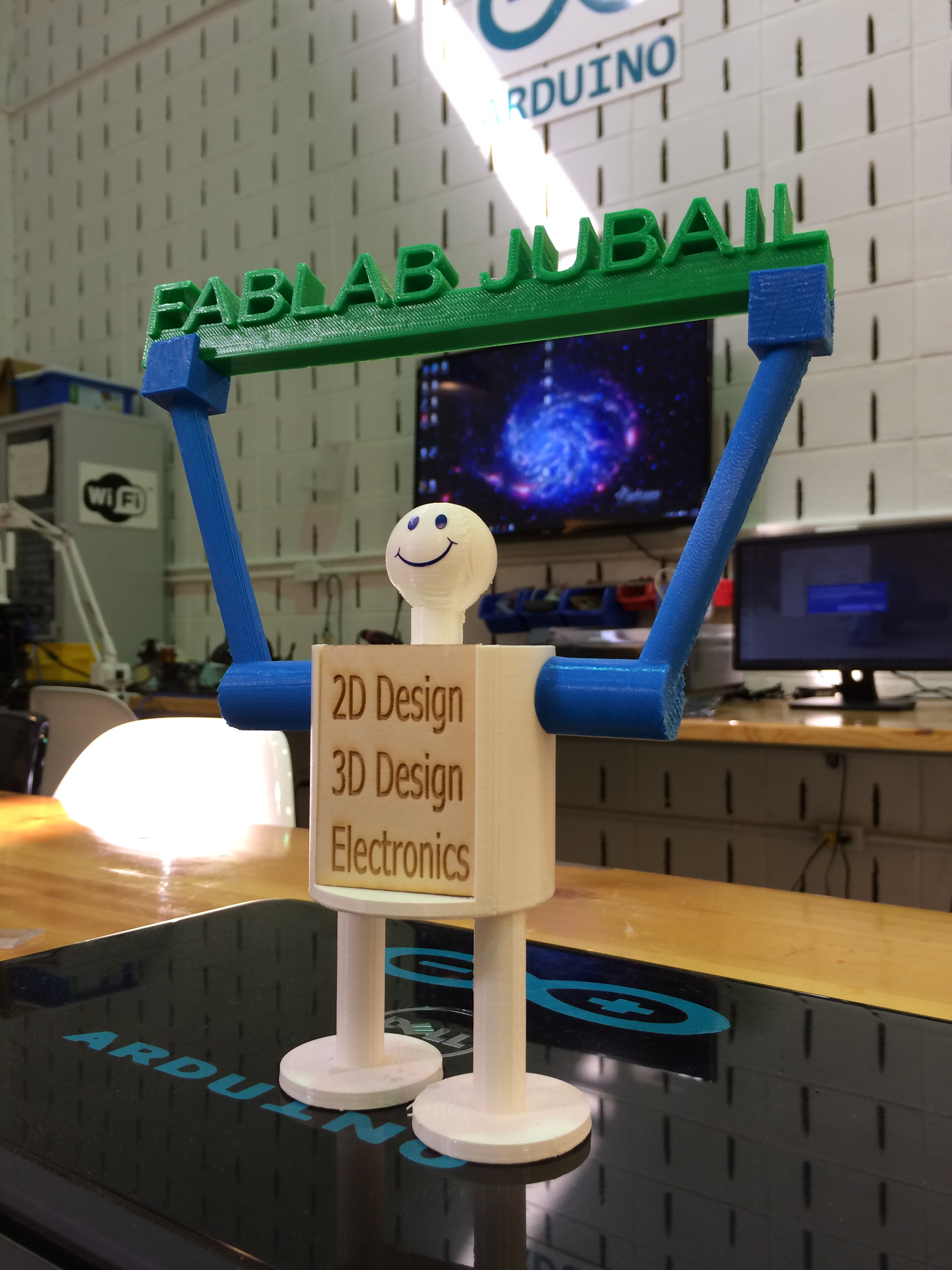
Then I moved to the scanning as it's part of this week assignment, I was so excited to test the scanning as I've never tried the process. Using my mobile phone to scanne 3D objects by downloading Scann3D program (Andriod from Play store)
Unfortunately, the results were bad and I could not upload them. It's very difficult to get good scanned model as you have to move slowly and be very careful. It took several hours but nothing good
I moved to another tool, which is desktop 3D scanner machine called matter and foarm It's very simple and useful machine

I used 3D printed part (dinosaur) to make 3D scanning


By opening MF software that provided by the same company Matter & Foarm
First of all, I have to make callberation to make sure the detection will be perfect and the device is ready to use in terms of the lighting and position
Just starting the scanning process. The camera detects the object for the first time

The laser starts working and pointering on the object. I edited the contrast and texture setting accordingly. The program shows the time needed to make the scanning

The result was not fine, I read more than I know that I have to make calibration at first the same place that I'm going to make the scan. I started the process by putting the calibration card on the space of scanning
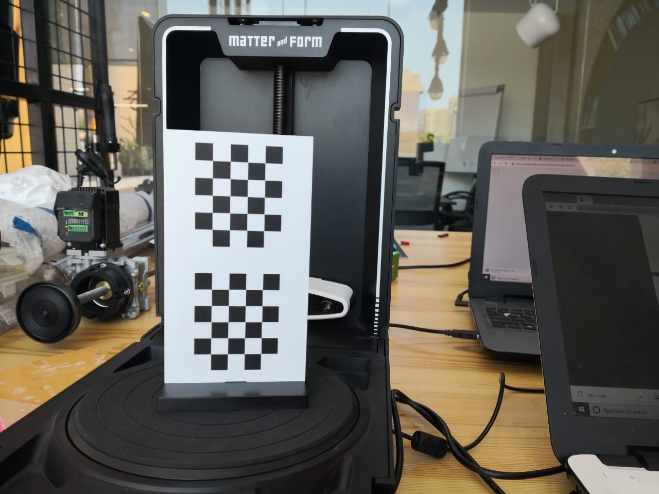
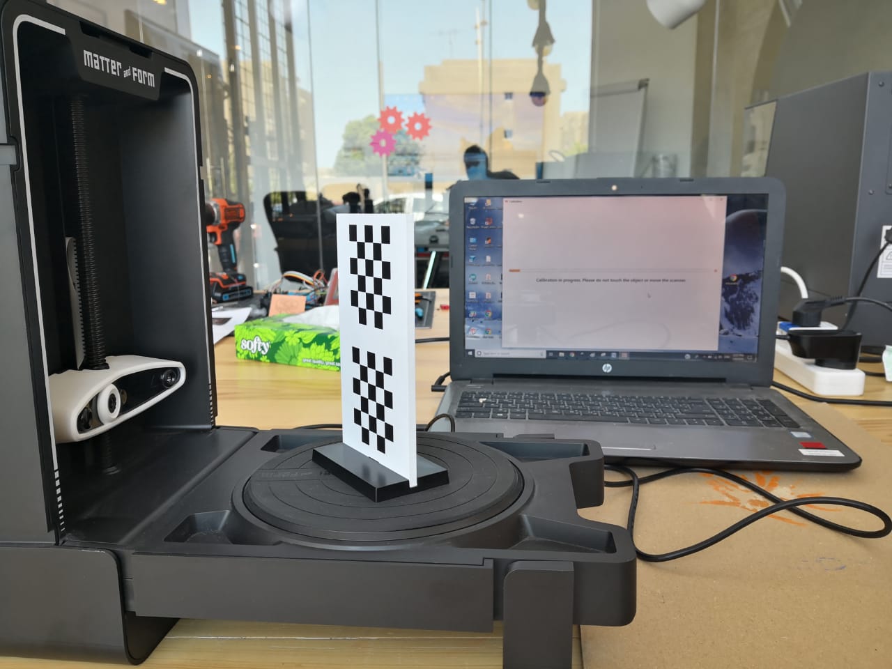
Then I opened the program and clicked on celebrate. I followed the steps as requested on the screen, then I got the message that the calibration is done
I put the design and start scanning process, it needs 1h and 30 min
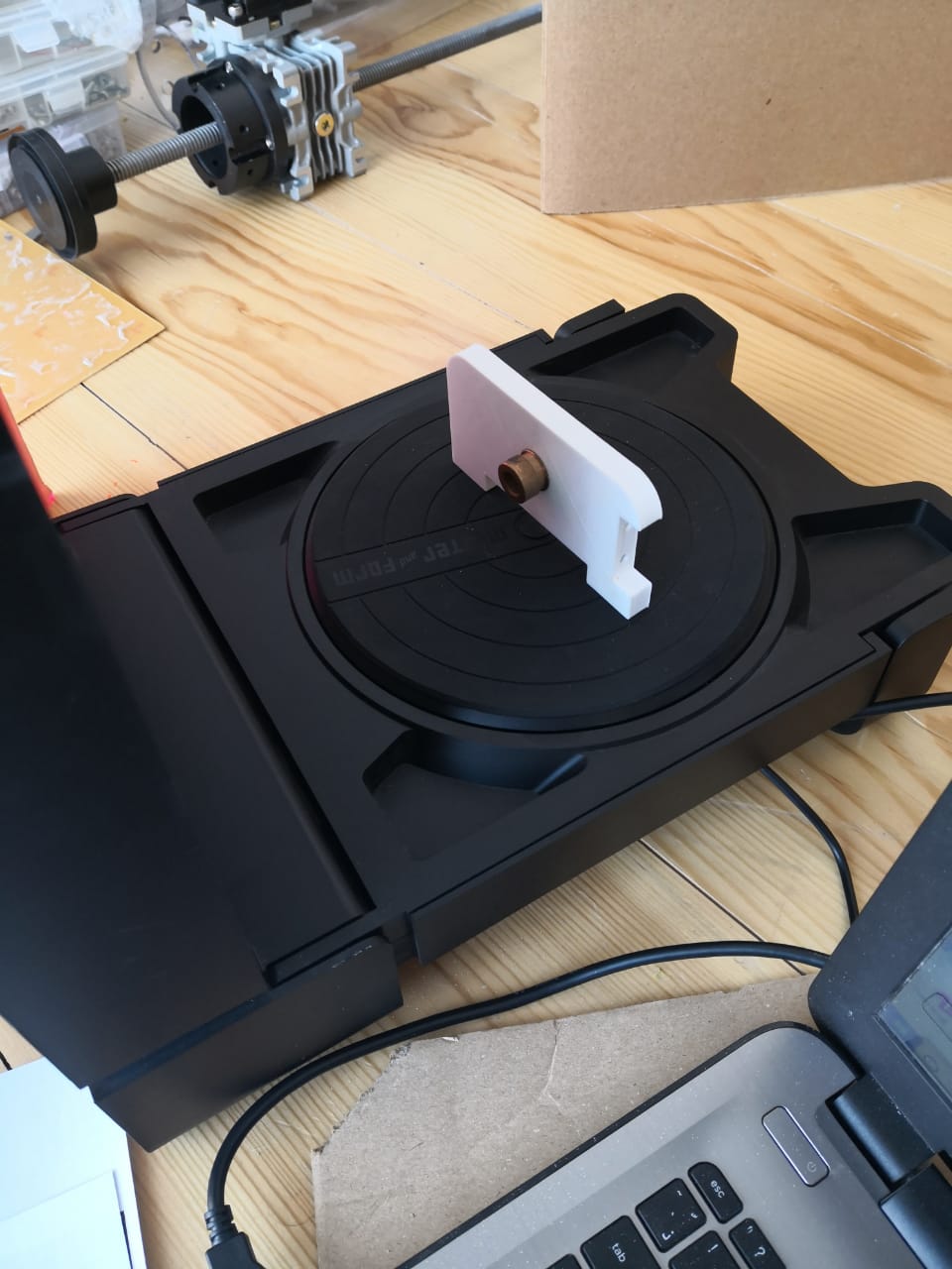
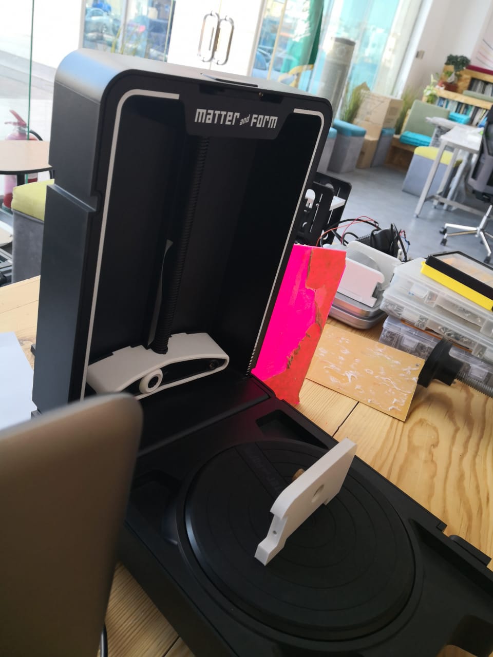
I checked the scanning after one hour, it was going smoothley
The scan is done. I removed the additional material in the result
I clicked on mesh and saved the design as STL
Group Assignment
The group assignment for this week is to test and design rules for 3D printers. I worked with my coluges Hussain Alhudhud and Mass
We designed something and I tested the printing using SLIC3R and Prusa i3 MK3, I used PLA and 0.15 mm resulution. Here are the steps from exporting the file to start printing and get the object done

We selected the file as we saved it on the SD card

After pressing on the file, the printer started heating up the bed and nozzle

This is the filament spool that We used, as mentioned it's PLA and 1.75mm diameter

The process went good and the print is excellent as shown below


Download Files' Links: