-
Assignment
Electronics ProductionElectronics Production
I like electronics! doing circuits and smart systems, maybe because these stuff related to my major. But I have not done PCB circuits using Roland milling machine. I've tried that once before using laser cutter with non-refliction tape. I was so excited to get this done
This week, I should make in-circuit programmer, there are many options available to mill and program. Each one has a microcontroller chip with other components to be in circuit programmer. This can be used later to program our microcontroller boards
By checking the tutorials, I chose the board that has Attiny44 microcontroller chip

Then I moved to use the Ubuntu OS to use Fab modules website
FabmodulesAlso, there is a ready to mill file that I can upload to start milling

I did import the design as png, the website is very easy to use
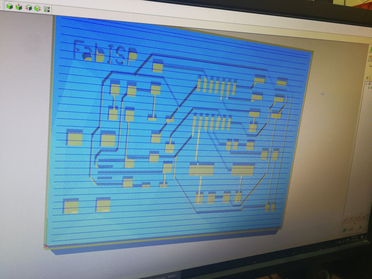
By selecting the Roland mill and 1/64 inches bit to make the paths. Then I cliked on calculate
The website works perfectly! and I import the PNG layout file and export rml file, I used Roland MDX-20 milling machine to start create the paths and edges cut
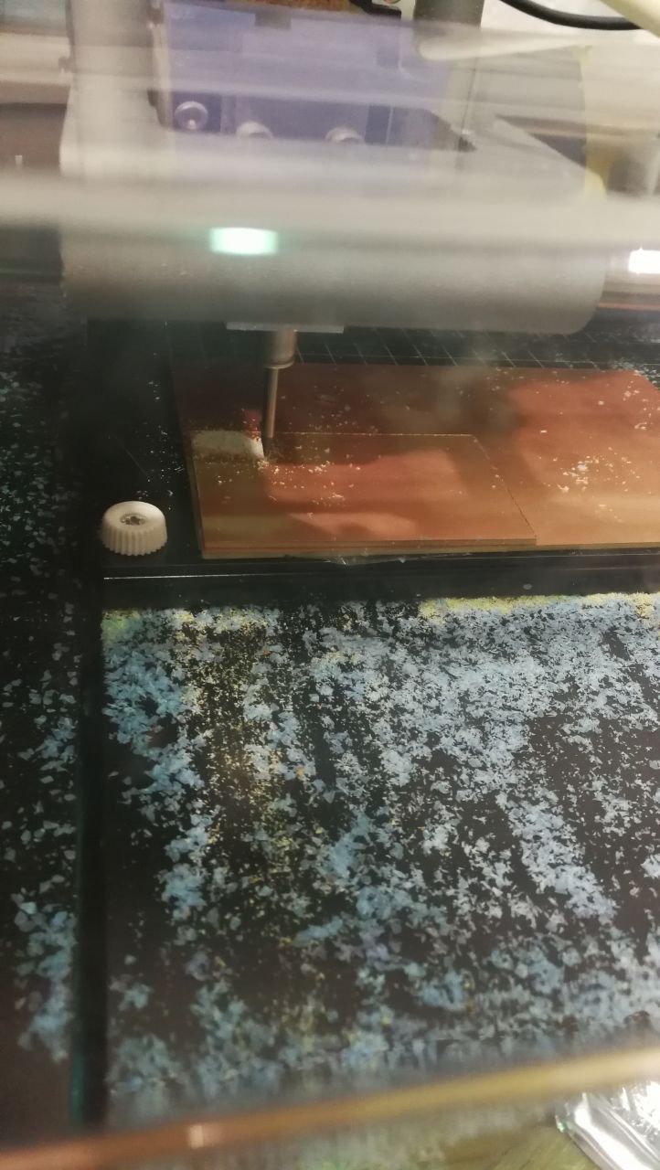
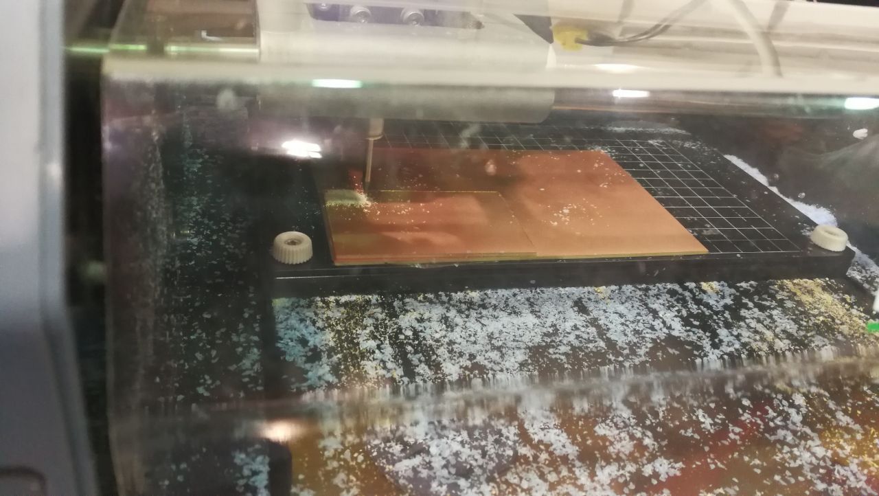
Finlly ,,, I got an amazing one!
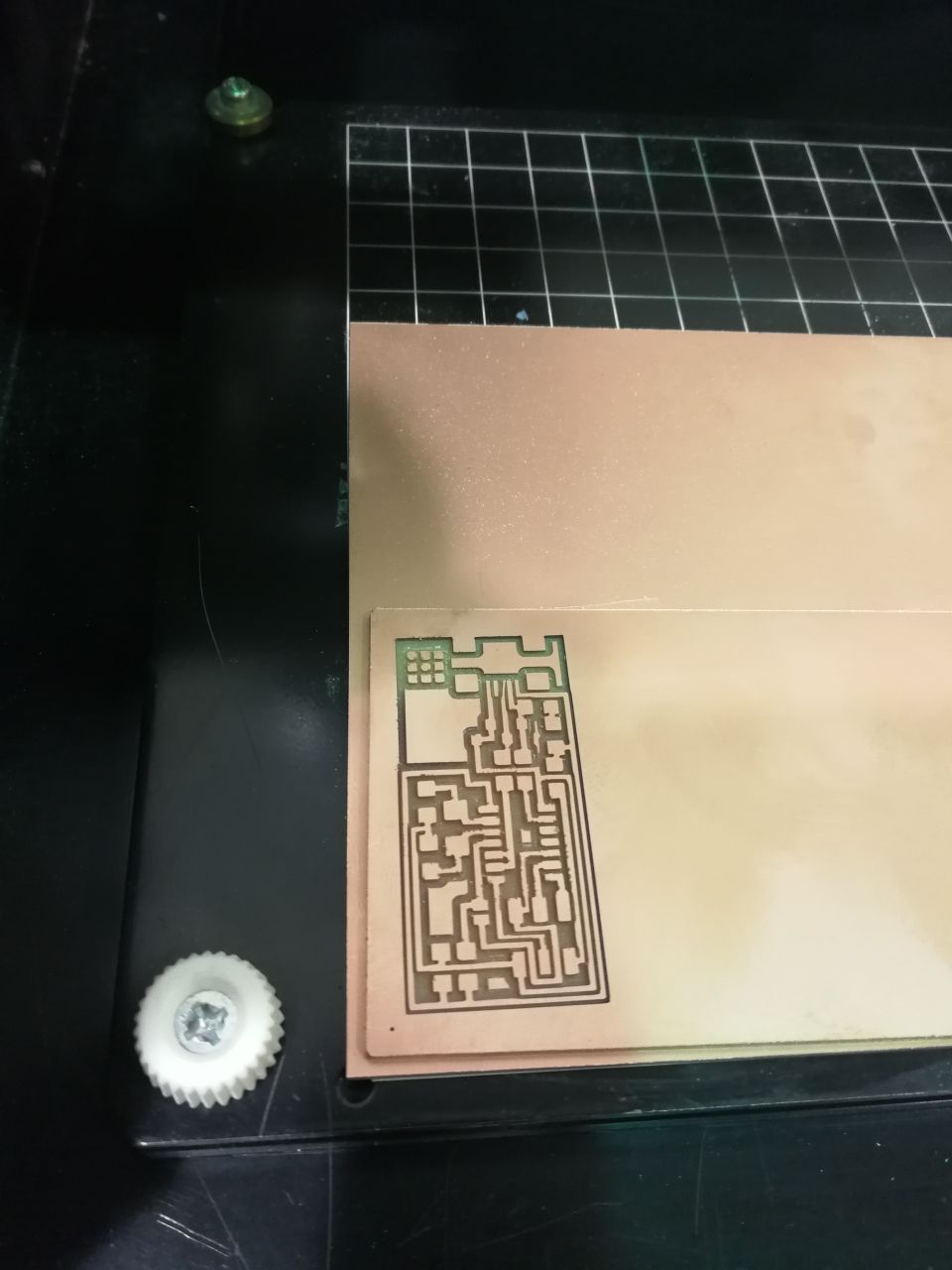
To do more with milling. I was thinking to do this in easy way. We have Carvey machine but I have never tried milling the PCB using it. I opened the traces (PCB sketch) using inkscape program and then saved it as SVG format to import it using Carvey website, because the platform that runs the machine is web-based called Easel

The PCB boards here can be fixed without double sided tape, however, you can use big sucrifice sheet to protect the bed and fixed the PCB board on it
I got PCB copper board, first I have to unscrew the blue screw, and then put the board below the black corner and screw the blue screws once againg

To make sure that the board is fixed well and nothing will move during the milling, I should screw the clamps around the bord in the avilable holes on the bed

After getting board fixed, I looked at the bit and collet to use the suitable one, I used the tools to hold the neck and undo the collet to replace the bit


We have many bits, I used 1/64 to do the paths (traces) because it should be very accurate

Now, the bit is fixed as well

I'm planning to try another design, which is Attiny45 based (FabTinyISP)

This is the schematic diagram, shows the microcontroller pins and the other components such as capacitors and resistors

Traces image is ready as png, I downloaded it

I opened the software Easel, which as I mentioned web-based. I changed the material to be PCB and set the material dimensions
I imported the traces by clicking on import and selecting image trace
The board is imported and I can check the preview
The file being imported using the web based Easel. I did the settings, the feed rate is 180 mm/min, and the plung rate 90 mm/min
I run the machine to start milling process by pluging the usb cable and clicking on Carve

I started the job after importing the file. The first one is damaged because of the overlapping the designs between milling the traces and cutting the edge as shown below

The second one is also perfect in terms of milling the paths


But I felt that it went too much down as it will be cut not only milling, so I changed it to test somthing else. This one I went down only 0.4 mm and it seems not okay as shown below

I cut the borad and get the results
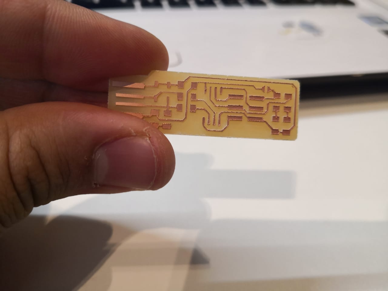
Getting more experience dealing with these designs and running the machine many times, I got the final one and I think it's very good to start soldering process. I used 1/64 inches to do the milling for the paths and 1/32 inches to cut the outer shape. I started soldering the following components:
- Attiny45
- 499 ohm resistor x 2
- 49.9 ohm resistor x 2
- 1 kohm resistor x 2
- 3.3v zener diode x 2
- 100 nF capacitor
- RED and Green LEDs
- ISP header
The results were good, I checked it using multimeter to make sure the paths are connected

To build the firmware, I used this guide step by step. I downloaded the firmware source code then I opend Git Bash and started excuting the following comands
- I need the right path, so the unzip folder is in the desktop, I need to be inside it by executing: "cd Desktop" and then "cd fts_firmware_bdm_v16" or the name of unzip folder
- Then, I wrote "make clean" and then "make" , this is to remove .hex files and build again new ones. If I checked the folder now, the following files and folders will appear
- Now, I connected the board to Arduino (the arduino should have ArduinoISP code uploaded before). I used 6 pins to connect it (6 isp pins). Now the LED is lighting up
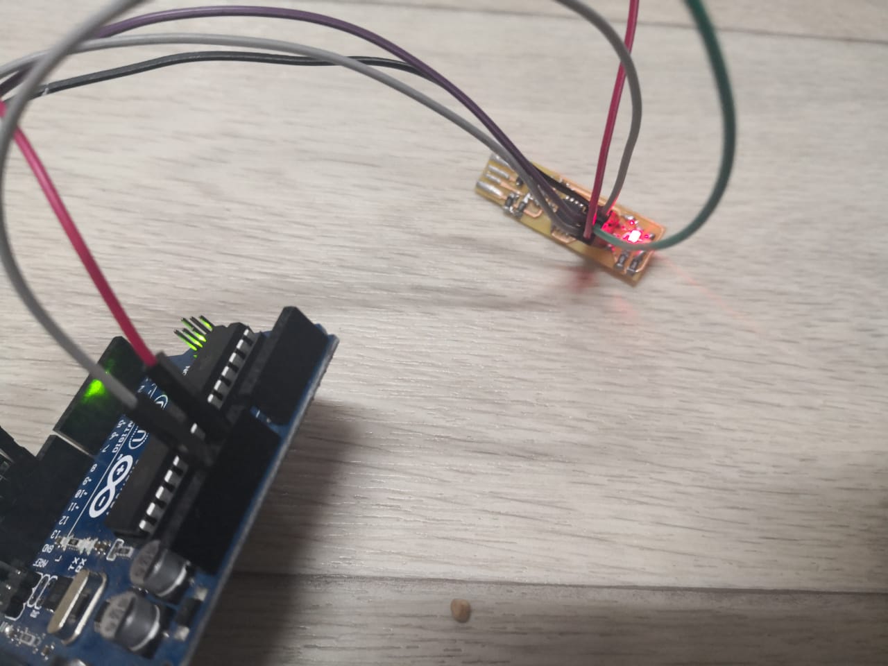
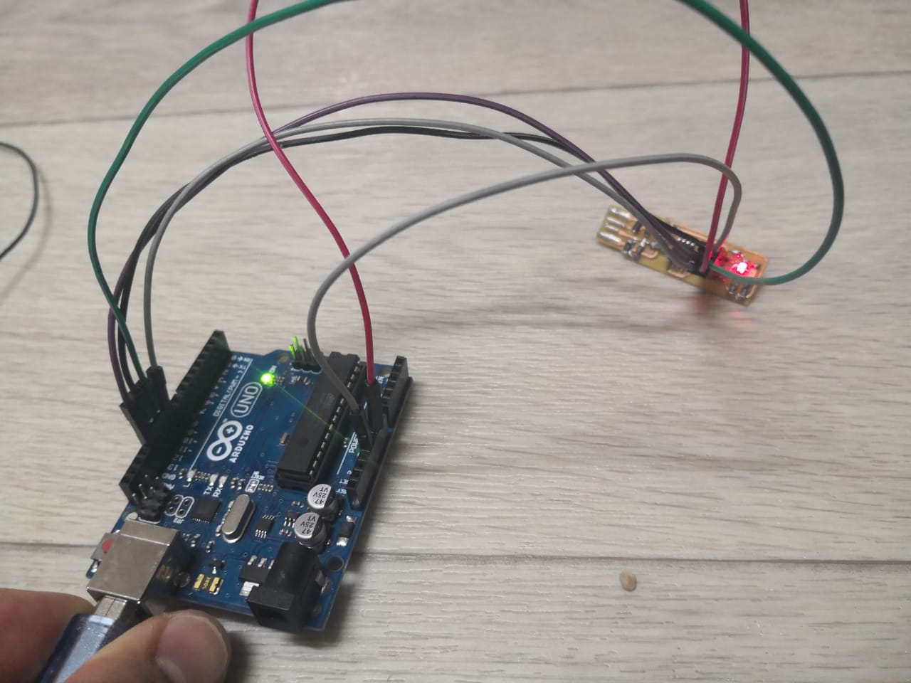
- I run the following commands one by one to build the firmware: "make flash" and then "make fuses" after that "make rstdisbl". The results as shown below
- Now, I pluged the board that I milled and soldered. The red LED is on. It's recommended to use usb cable or hub, but I do not have here
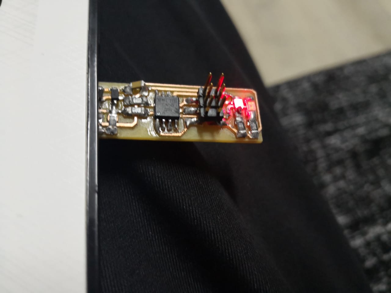
USBtiny can be recognized by clicking on "device manager" as the follwing

I did try many things this week, such as building the circuit and connecting it to check the results and to use more techniques
First I started to build the circuit from scratch in order to arrange the paths and get the simulation before circuit fabrication. I used Fritzing software it's realy useful and easy to use. I used to use proteus software to do the testing and simulation with schmatc digram as well. I will start explaining what I did exactly
1. Fritzing Software
I downloaded the software
then I started implimenting the circuit by putting the components and making circuit connection. The goal of our assignment is to build ISP (in-system programming) to be able to program the circuit through USB, let's define the circuit main component attiny45

The circuit impelemintation using Firtzing, breadboard view
The circuit impelemintation using Firtzing, schmatic view
The circuit impelemintation using Firtzing, PCB layout
I tried to do the PCB using extrude tool in the Onshape, and then open the file using Milling machine software
