-
Assignment
Computer Aided DesignComputer Aided Design
This week, we are going to make model (raster, vector, 2D, 3D, render, animate, simulate, ...) using different programs and tools
I used to design and cut/print the objects, but this is the first time that I know the differences between Parametric (CAD) programs and normal ones. In general, Parametric models contain formulas and relations that can change everything by changing one prameter
In this tutorial, I'm going to test Onshape, which is parametric. And Inkscape, which is non-parametric


I will start with Onshape It's web-based software. You have to create new account and then start playing with it by creating new workspace
As shown in the above screenshot, the program allows you to start sketching using different views, I select the top view only as I'll start with 2D sketches. I hide the other plans
I looked at the toolbar, it contains many options for sketching such as shapes, combine, mirror, and so on. I selected a rectangular and one circle, and then I did mirror to get the same circle in the other direction (I added the line because you should select the line of mirroring, to do the mirror with reference to it)
After making some steps includes (mirror, trim, offset, ....etc.) I got this two parts fit to each other
I tried extrude (1 inch) and I got the following
By doing some other steps, I got finally the parts well connected as a buzzle
Trying some icons as well such as shell, and getting the new amazing things
Now, and to show the parametric design features, I added a variable to change as the following to start changing it and the whole design should change accordingly. I added the first variable by selecting variable icon from the tool bar or searching using variable word
I did name the variable X and the initial value is 0.3in .... I moved the variable at the top to make sure that is known as global variable
I was setting the extrude for both 1in but I need to change them at once by adding the variable X as the depth, but it should be #X (adding # before the variable as the following
Now, the whole design depth will be changing as the variable X is changing, the depth now is 0.3in as the variable is 0.3in
I tried to make the variable 1.5in to see what happened by selecting the variable and make it 1.5in
Once I pressed the true mark, the design will be updated accordingly
To check the design link, Click here
To download the design, Click here
Using Inkscape to create vector and raster and how to design by selecting simple tools and use them
I started a new project and used three main tools from the toolbar, which is creating a rectangular or a square, creating stars and polygons, and adding a text
Now and by selecting an object or set of them, I could make it fill or stroke, stroke means keeps the edges and remove the fill. I opened fill and stroke from object >>> fill and stroke. So, as for the star, I planned to make it raster by filling it, I clicked on fill and select the color as black. I clicked on stroke and then X means no stroke needed
As for the rectangles, I need it vector for cut. I selected it and clicked on fill to be X and stroke only. Also, I can change the edge thickness by clicking on stroke style
I used the align and distribute from object, to make the alignment. By that, I can make sure that the star position in the middle of the rectangular
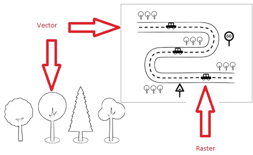
Design file hereDoing another example to use more features and the difference between vector and raster. I did try the bezier curve to make lines and joints, also trace bit map to convert a picture into vector

I'm planning to design a traffic signal using Onshape, I created new document and started new sketch doing the base by cliking on the circle and made two circles, the outer is 29mm and the inner is 8mm
I extruded the outer circle, the depth is 4mm to be as the base for the traffic signal
Also, I extruded the outter circle by 80mm
To build the body of the traffic signal, I created new sketch on the top of the inner circle to be extruded on the top
I extruded the rectangular by 100mm
The LEDs should be fixed on the body, I created new sketch on the body to remove the places for 3 LEDs if I want to fix. I did the spaces between each one is 30mm
I ckliked on the extrude and then remove, to remove the material instead of extrude
Finally, I got the results that I was thinking to do
To check the design link, Click here
To download the design file hereAfter testing some features... I started final project drawings by making some sketches at first to determine some dimensions. I used Onshape to imagine the full prototype in terms of designing
The above figure describing the parts that I will start to collect and assemble to get the robot chassis. I used the second icon for assembling the robot parts. I used fastened tool to do the fixing after importing the parts one by one
Then I get it as final. It looks amazing!! :)
To download the design file here