-
Assignment
Output DevicesOutput Devices
In this week assignment, I'm going to test some output devices, which means the components that need signals to run such as the display, motors,...etc
I started with DC motor, it's normal DC motor and one of the DC motors types. But it's important to note that the DC motors need a huge current compared to the Attiny44 maximum ratings. Reference to the Attiny44 datasheet, the maximum current from any input and output pins is 40 mA. And 200 mA from Vcc with respict to the ground as total
Attiny44 Datasheet
I tested the motor that I have, it needs around 600 mA. This damages the microcontroller or the system hangs and nothing works. The solution is to have a different power supply and something to isolate the load but keeps the control signal from the Attiny44 board. I have transistors which used usually to do the job, so it can take the control signal from Attiny44 microcontroller board and on the other direction the motor will be connected with different power supply. The transistor that I have is called IRF520

IRF520 is a power MOSFET (metal oxide simiconductor field effect transistor). it has 3 terminals, first one is called Gate (connected to microcontroller to receive the control signal), the second one is called source, and the third one is called drain
Reference
As I mentioned the microcontroller board can't give the power needed to run the motor, I used a power supply to be the main source for running the motor. In this case I had to connect the GND for the microcontroller board to the power supply GND to collect the sink so the control signal works accordingly. The wall power supply that I have here is 5.1v and 3A. I tried to connect the motor directly and it worked perfectly

So, these are the main items that I used to test the DC motor. I started programming and preparing the code. It's simple as I'm going to test the motor at deferent speeds

I used pin ADC5 as an output in Attiny44 because it can generate a variable voltage to control the speed of the DC motor. The Attiny44 microcontroller can't generate a real variable voltage levels, but this can be done using a technique called PWM (pulse width modulation) it's all about switching the output voltage using different duty cycle (the equation for duty cycle is (Ton / (Ton + Toff)). This pin will be connecting to the gate (Power MOSFET pin) and the different voltage levels make the load voltage variable
The output voltage from the pin is between 0-5 volts, but in programming, the value would be between from 0 to 255. 0 in programming means 0 voltage, and 255 means 5 volts, and so on. I used 4 different values to check the speed starting from 0 up to 255 as full speed. between them a delay
I connected the microcontroller board Attiny44 to the Arduino in order to program it as I did in embbeded programming week and input devices week. Once the code is uploaded, I disconnected the microcontroller board Attiny44

After removing all the wires that were connected to the Arduino for uploading the code, I started connecting the circuit to run the DC motor, I found a good refernce to follow. I fixed the transistor that I have, power MOSFET(IRF520) and it's important in this case to connect the diode as well to protect the transistor from motor current after stops. The diode that I used is diode 1n4007 that allows the current to flow in only one direction. The diode has two terminals, one is called Anode and another one is called Cathode. As the LED but it does not light up

Then using the testboard to fix the components, started with IRF520 and 1n4007

I completed connecting the circuit using the following components:
- Power MOSFET IRF520
- Diode 1n4007
- 5.1v 3A wall power supply
- Jumper wires
- Normal DC motor

taking the signal from ADC5 in Attiny44 (pin8) to IRF520 transistor gate pin by using a jumper wire

Finally, and by connecting the FTDI cable to power up the circuit and connecting the wall power supply, the motor run as programmed
I tested the servo motor, it's a motor that can move with respect to the angle. In this case, many applications require this type of motors, such as automatic gate system and some security systems to move the camera as so on

The servo motor has three main terminals, one is red (VCC 5 volts), one is brown or black (GND), and the last one is orange (signal from the microcontroller). The motor moves by obtaining the angle and it can move continuously or stops in different angles
I prepared the first code for testing the servo motor but it did not work as I was building the code based on the Servo.h library. I searched and discussed this issue with our mentor Danielle and we discovered that the library is not compatible to function with my Attiny board. Then I used the following code without using library
The code is basically to move the servo motor forward and backward different angles, I planned to use pin number 7 which is ADC6 so it's pin 6 in programming as it can generate PWM meaning variable voltage levels. I created two variables one of them called servo which is the pin connected to the servo and another one is called i which used as a variable that changes to create a movement (the voltage level)
I built the whole code based on the loop, which is for loop. This loop helped me to generate a continuous voltage level changing (the variable i) and starting from zero up to 120 and the delay is very small (1 millisecond) and getting back from 120 to zero. The for loops take 3 arguments, the first one is the variable starting point, the second one is the condition that the program will access the loop if the condition is true, the third one is the equation (maybe increment or decrement) after each access
I connected the Attiny44 board to the arduino using 6 pins to upload the code, once the code is uploaded, I disconnected the board and connected the servo motor with Attiny44 board using 3 pins (VCC, GND, pin 7 (ADC6)) in addition to connecting FTDI to power up the board

Now, the motor is running correctly forward and backward
Our global mentor requested new design to meet my needs in the input and output devices. I started new microcontroller board design, I selected Attiny44 to design, as the inputs and outputs devices that I selected can be connected and programmed using this microcontroller chip. I created new project using Eagle program and started collecting the components needed
I did the connection similer to what I have done in hello world board. Now I started connected the paths to do the traces done to start milling process

I got the board ready after milling, drilling and cutting
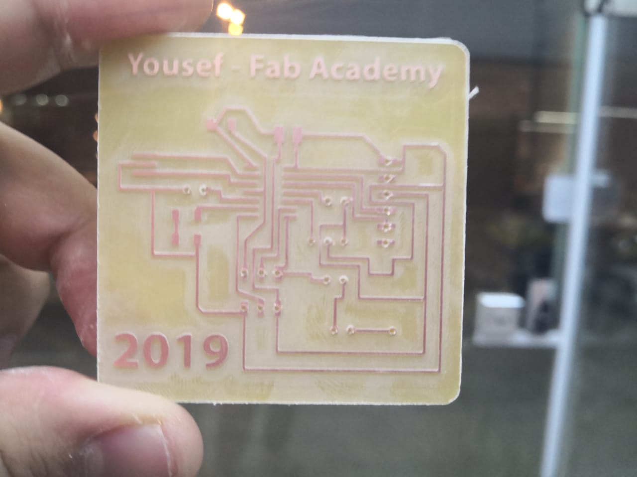
I started the soldering process with the microcontroller chip, Attiny44
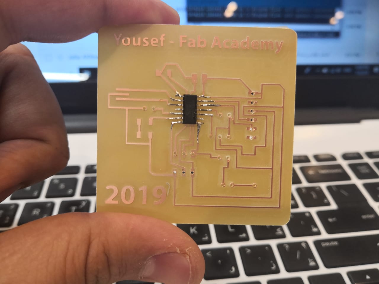
I complete the soldering process
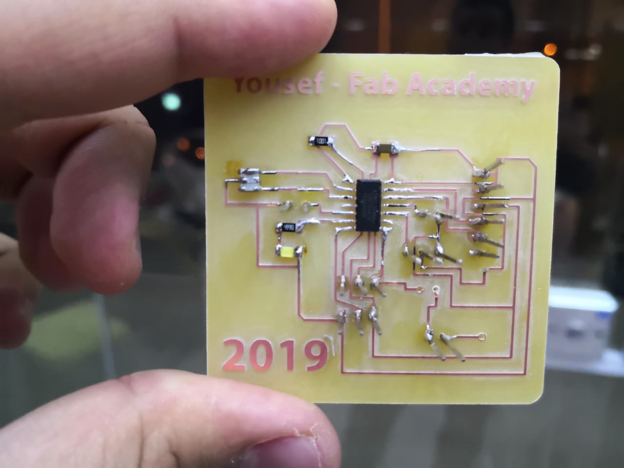
I added the final components which are the power transistor and diode
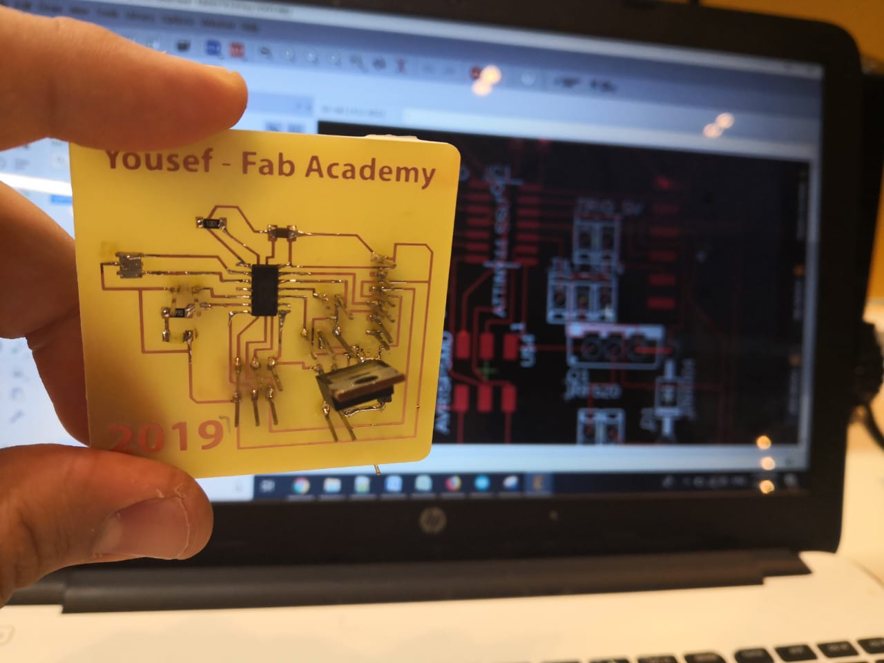
I tested the board using multimeter before I start program it. I'm planning to use an Arduino as ISP to transfer the code to my board. I tested the code by uploading blinking code (my LED is connected to pin 7)
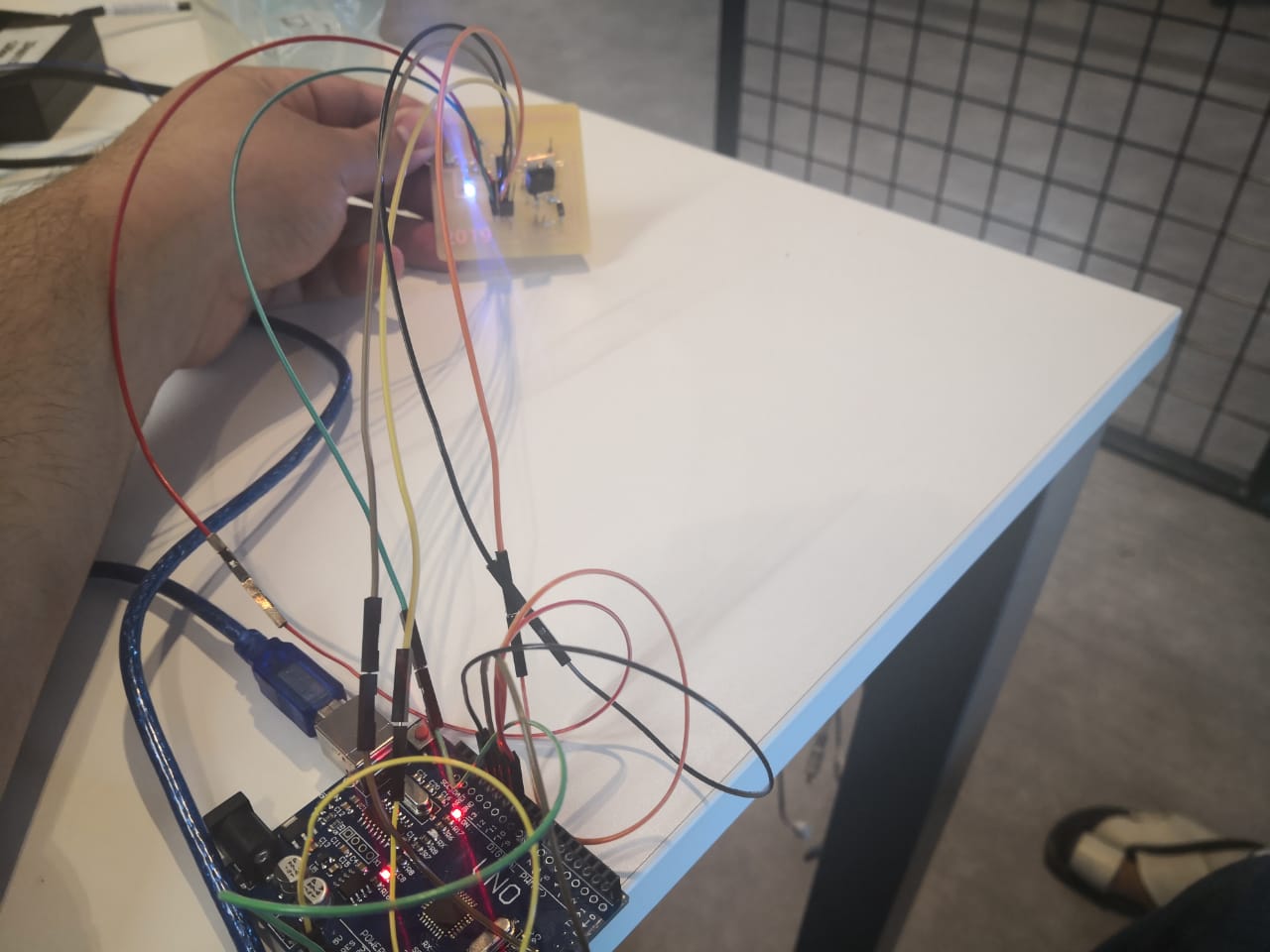
Now, I connected the motor that I have on the ports that I exposed espically for the motor with transistor IRF520 driver, I used the same wall power supply that I used above. The motor can be controlled using pin 5 as it's connected to gate in the transistor
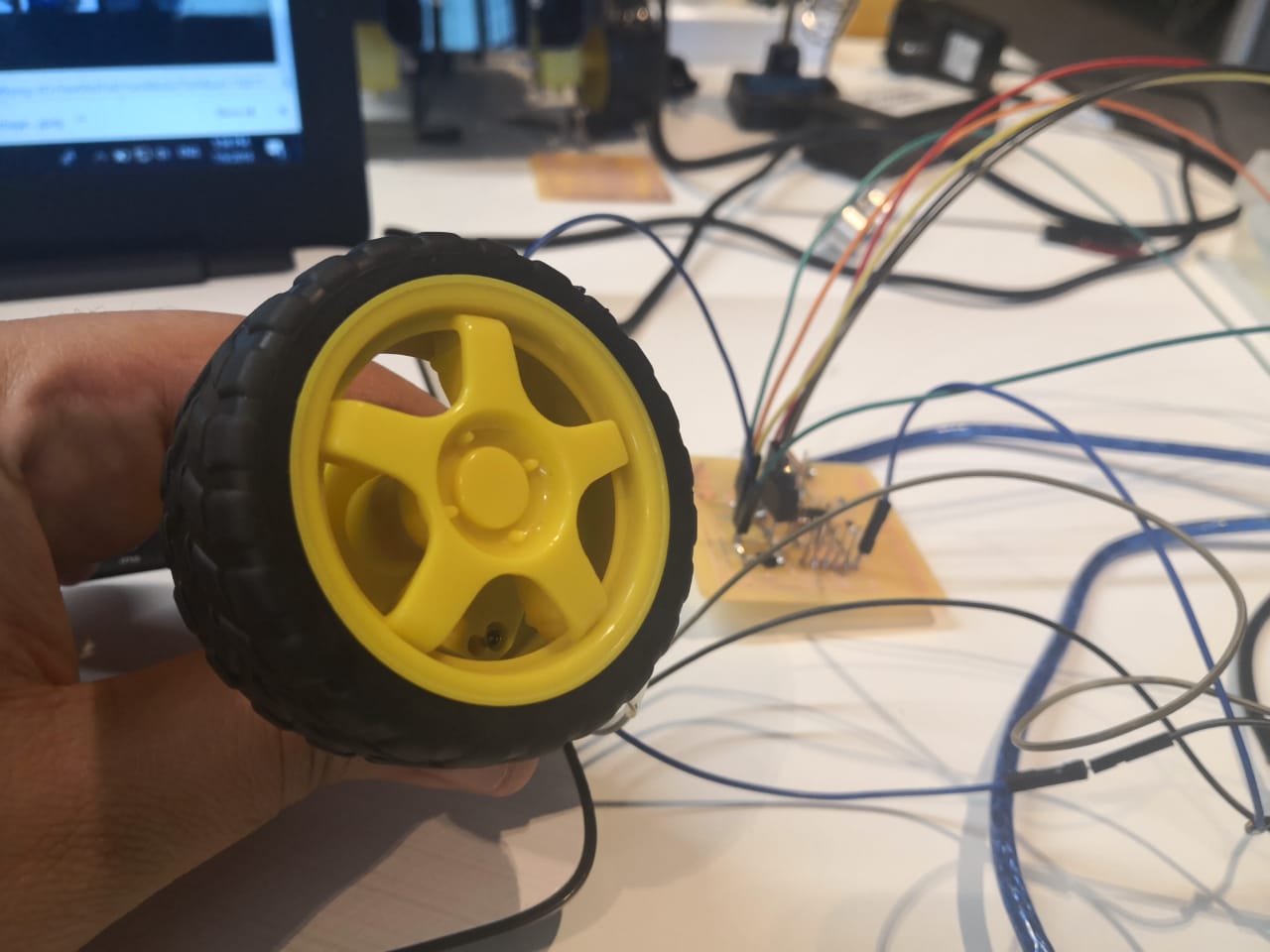
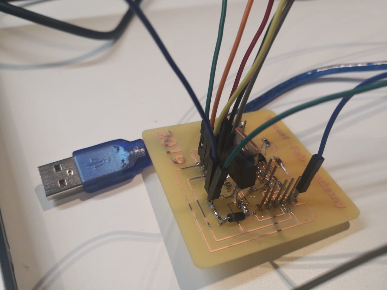
I connected the board to an Arduino to upload the program, I used the same code that I used above
I recorded a video of the working
Now, I connected the servo motor to my board, the servo motor has 3 pins as I mentioned above, one is 5v, the other one is GND, the last one is signal, I connected to the pin 5

Now, I used the same code that I wrote above, I connected the Arduino and uploaded the code but changed the pin to 5
I recorded a video of the working
Download files:
DC motor code here
Servo motor code here
Eagle board design here